
Recommended
More Related Content
What's hot
What's hot (20)
Similar to The Optimal Process for a Vacuum Cleaner Fan
Similar to The Optimal Process for a Vacuum Cleaner Fan (20)
Recently uploaded
Recently uploaded (20)
The Optimal Process for a Vacuum Cleaner Fan
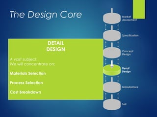
- 1. The Design Core Market Assessment Specification Concept Design Detail Design Manufacture Sell DETAIL DESIGN A vast subject. We will concentrate on: Materials Selection Process Selection Cost Breakdown
- 2. Systematic Process Selection Subset of Processes Supporting Information: handbooks, suppliers data sheets, databases, WWW (Search “family history” of candidates) All Processes Screening: apply attribute limits (eliminate processes that cannot do the job) Ranking: order by relative cost (find processes that can do the job economically) Prime Candidates Local Conditions (does the choice match local needs, expertise etc.?) Final Process Choice
- 3. Categories of Component Shape SLENDERNESS Ratio of section thickness to the square root of section area: Similar to aspect ratio in 2-d A t s = COMPLEXITY Relates to the number of specified dimensions of the component and the precision required: But life is more complicated, e.g. spheres have low complexity, but are difficult to make compared with cylinders of ∆ = L L nC 2log
- 4. Process for a Vacuum Cleaner Fan Constraint Value Materials -Nylon -Al alloys Complexity Minimum section Surface area Volume Weight Mean precision Roughness Process Tm = 550 - 573 K, H = 150 - 270 MPa ρ = 1080 kg/m3 Tm = 860 - 933 K, H = 150 - 1500 MPa ρ = 2700 kg/m3 2 - 3 1.5 - 6 mm 0.01 - 0.04 m2 1.5x10⁻⁵ - 2.4x10⁻⁴ m3 0.03 - 0.5 kg ±0.5 mm <1 µm Net shape preferred Fans for vacuum cleaners are designed to be cheap, quiet and efficient. Nylon and Al alloys have been identified as candidate materials. Net shape processing is preferred for low cost. Complexity is classified as 3-D solid.
- 5. Process for a Vacuum Cleaner FanSLENDERNESS Process choice is often limited by the capacity to make long, thin sections (slenderness S of a component), where A t S = The fan can be shaped in a large number of ways including die-casting for Al alloys and injection moulding for polymers. The hot working processes for metals cannot be chosen. Define a search region that has limits a factor of 2 on either side of the target values.
- 6. Process for a Vacuum Cleaner FanCOMPLEXITY The micro-electronic fabrication methods and sheet working processes for metals are eliminated. The search region falls in a regime in which many alternative processes are possible. Hence, in this case, we learn nothing new. Define a search region that has limits on either side of the target values.
- 7. Process for a Vacuum Cleaner FanHARDNESS / MELTING POINT In this case almost all processes for polymers and metals are viable. Only electron beam casting is eliminated. Hence, in this case, we again learn nothing new. Define search regions that have limits on either side of the target values.
- 8. Process for a Vacuum Cleaner Fan A significant number of processes are eliminated. A number of polymer moulding processes, including injection moulding are acceptable. Machining from solid meets the specifications, but is not net-shape. Many casting processes are eliminated, but pressure die-casting, squeeze casting and investment casting are acceptable. SURFACE ROUGHNESS In the designer’s view, it is the surface finish is the discriminating requirement. It (and the geometry) determines the fan’s pumping efficiency of and influences the noise it makes. The design constraints, R < ±1 µm and T < 0.5 mm, define the search region on the tolerance/roughness process selection map.
- 9. Process for a Vacuum Cleaner Fan Process Comment Nylon and Al-alloys Machine from solid Electro-form Al-alloy only Cold deformation Investment casting Pressure die casting Squeeze casting Nylon only Injection moulding Resin transfer moulding Expensive, not a net-shape process. Slow, and thus expensive. Cold forging meets the design constraints. Accurate, but slow. Meets all the design constraints. Meets all the design constraints. Meets all the design constraints. Meets all the design constraints. N.B. The charts can only narrow the choice. There are other considerations of course: capital investment, batch size and rate, supply, local skills etc. A cost analysis is now required to establish the best choice.
- 10. Forming Ceramic Tap Valves Constraint Value Material -Zirconia Complexity Minimum section Surface area Volume Weight Mean precision Roughness Tm = 2820 K, H = 15000 MPa ρ = 3000 kg/m3 1 - 2 5 mm 10-3 m2 1.5x10⁻⁶ m3 4.5x10⁻³ kg ±0.02 mm <0.11 µm Vitreous alumina is commonly used in hot eater valves, but it may not be the best due to thermal shock. The materials selection procedure offered Zirconia as a possible alternative. How should the valve discs be shaped?
- 11. Forming Ceramic Tap ValvesSLENDERNESS Process choice is often limited by the capacity to make long, thin sections (slenderness S of a component), where A t S = The ceramic discs are not particularly slender. Some metal forming and polymer moulding processes are eliminated, but we would not expect to use those processes for ceramics in any case. Hence, we do not learn much. Define a search region that has limits a factor of 2 on either side of the target values.
- 12. Forming Ceramic Tap ValvesCOMPLEXITY The micro-electronic fabrication methods and ceramic moulding processes are eliminated. Powder routes, machining and molecular methods are viable alternatives based on complexity. Define a search region that has limits on either side of the target values.
- 13. Forming Ceramic Tap ValvesHARDNESS / MELTING POINT High melting point and hardness are restrictive. Machining is now eliminated. Electron beam casting, electroforming, and CVD and evaporation methods are possibilities. Powder routes emerge as the practical alternative, but can these methods adhere to the tolerance and surface finish required? Define search regions that have limits on either side of the target values.
- 14. Forming Ceramic Tap Valves The design constraints, R < ±0.1 µm and T < 0.02 mm, define the search region on the tolerance/roughness process selection map. Powder routes are now eliminated as they cannot give the required tolerance and surface finish. Mechanical polishing is possible. SURFACE ROUGHNESS The surface of the discs must be flat and smooth to ensure a good seal between the mating faces.
- 15. Forming Ceramic Tap Valves Process Comment Powder methods CVD and evaporation methods Electron beam casting Electro-forming Machining Capable of shaping the disc, but not desired precision. No CVD route available. Other gas-phase methods possible for thin sections. Difficult with a non-conductor. Not practical for an oxide. Material too hard, but polishing is possible. No single process is ideal for producing the ceramic valve discs from zirconia. A combination of processes emerges. Powder methods can be used to form the discs. The mating faces could then be polished to the desired tolerance and surface finish.
- 16. Process Selection: Cost Three rules for minimizing cost 1. Keep things standard: It is cheaper to buy a standard part than make it in house. If nobody makes the part you want, then design it to be made from standard stock materials, and use as few of them as possible. 2. Keep things simple: If a part requires machining then it will need to be clamped. Keep it simple so that the number of times it has to be re-jigged is minimized. If a part requires casting the minimize re-entrant angles which require complicated and expensive dies. 3. Do not over-specify performance: Higher performance increases cost. Higher strength alloys are more heavily alloyed with expensive elements. Higher strength materials require more energy to form. Increased tolerance leads to higher machining or finishing costs.
- 18. Process Selection: Cost Economic Criteria for Process Selection
- 19. Cost Modelling Resource Symbol Unit Materials: Capital: Time: Energy: Space: Information: inc. consumables cost of equipment cost of tooling basic overhead rate power cost of energy area cost of space R&D, royalty payments Cm Cc Ct Ce A Ci $/kg $ $ $/hr kW $/kWh m2 $/m2 h $/yr LoC P sC The producing a component consumes resources (see below). All processes consume these resources to some extent and thus a resource based approach is useful at the broad level we are dealing with.
- 20. Cost Modelling [ ] [ ] +++++= se c c Lotm CACP Lt C C n C n mCC 11 Cost: where m is the mass of material used, n is the batch size (no. units), is the batch rate (no. units per hour), tc is the capital write-off time, and L is the capital load factor (the fraction of time over which the equipment is used productively) n Materials Tooling Time Capital Energy Space [ ] [ ] [ ]grossLtm C n C n mCC , 11 ++= Materials Dedicated cost/unit Gross overhead/unit This reduces to: o, Cost has 3 terms Materials costs: independent of batch size and rate. Dedicated capital investment (tooling, jigs, dies etc.): varies with the reciprocal of batch siz Time dependent (operators, space, power etc.): varies with the reciprocal of batch rate.
- 21. Cost Modelling: A Cast Connector Rod Cost parameter Sand Casting Die Casting Material, mCm Basic overhead, CLo(h-1 ) Capital write-off time, tc (yrs) Dedicated tool cost, Ct Capital cost, Cc Batch rate, n (h-1 ) 1 20 5 210 10000 5 1 20 5 16 000 300 000 200 0.1 1 10 100 1000 10000 1 10 100 1000 10000 100000 1E+06 Number of Components RelativeCostperComponent Die Casting Sand Casting Material Cost Labour (sand) Labour (die) . . The materials and process selection processes have identified the sand casting and die casting processes for a connector rod. Which process is economical? The cost of both processes is dominated by capital and tooling costs for small batch sizes; and dominated by materials and labour costs for large batch sizes. For very large batch sizes the cost of die casting is dominated by material costs. For batch sizes < 4000, sand casting is most economical. For batch sizes > 4000, die casting is most economical. All costs are normalized to the material cost
- 22. Process Selection: Cost 107 106 105 104 103 103 102 102 10 101 1 ANNUAL PRODUCTION UNITCOST Injection m oulding C ontact m oulding Vacuum form ing Blow m oulding
- 23. Fixed Costs Variable Costs Volume Total Unit Cost Setup: Material: 570g of grey cast iron $0.50 each 10 100 1000 $180.87 $18.87 $2.67 Tooling: $1.8k 8 impressions/pattern no cores Processing: 120 pcs/hr at $44/hr Setup: Material: 2.6kg of grey cast iron $2.30 each 10 100 1000 $243.77 $27.77 $6.17 Tooling: $2.4k 2 impressions/pattern 1 core Processing: 30 pcs/hr at $44/hr Setup: Material: 260g of yellow brass $0.713 each 10 100 1000 $163.21 $28.21 $14.71 Tooling: $1.5k no cores Processing: 4 pcs/hr at $50/hr Setup: Material: 180g of 712 aluminium $0.395 each 10 100 1000 $750.40 $120.40 $57.40 Tooling: $7k 3 cores Processing: 1 pc/hr at $50/hrCASTINGS: Sand (top), Investment (bottom)
- 24. Fixed Costs Variable Costs Volume Total Unit Cost Setup: 0.75hr at $60/hr Material: 1.11kg of 6061 aluminium $9 each 1 10 100 $75.00 $21.00 $15.50 Tooling: Programming 0.25hr at $60/hr Processing: 6min/unit at $60/hr Setup: 1.75hr at $60/hr Material: 1.96kg of 6061 aluminium $16 each 1 10 100 $386.00 $102.50 $74.15 Tooling: Prog’g 1hr at $60/hr Fixtures: $150 Processing: 55min/unit at £60/hr Setup: 5.5hr at $60/hr Material: 4.6kg ultra-high Mw PE $25 each 1 10 100 $646.00 $241.00 $200.50 Tooling: Programming 2hr at $60/hr Processing: 2.85hr/unit at $60/hr Setup: 2hr at $60/hr Material: 1.5kg of 6061 aluminium $12 each 1 10 100 $612.00 $396.00 $374.40 Tooling: Programming 2hr at $60/hr Processing: 6hr/unit at $60/hr CNC MACHINING
- 25. ASSEMBLY Part Data Assembly Times (s) Assembly Cost at $15/hr No. Parts: 16 Slowest Part: 9.7 $0.52No. Unique Parts: 12 Fastest Part: 2.9 No. Fasteners: 0 Total: 125.7 No. Parts: 34 Slowest Part: 10.7 $0.78No. Unique Parts: 25 Fastest Part: 2.6 No. Fasteners: 5 Total: 186.5 No. Parts: 49 Slowest Part: 14.0 $1.11No. Unique Parts: 43 Fastest Part: 3.5 No. Fasteners: 5 Total: 266.0 No. Parts:* 56/17 Slowest Part:* 8.0/8.0 $1.73No. Unique Parts:* 44/12 Fastest Part:* 0.75/3.0 No. Fasteners:* 0 Total:* 277.0/138.0 *electronic/mechanical
- 26. Product Life Cycle Development Introductio n to market Growth Maturity Decline TIME SALES
- 27. UNITCOST No. CUMULATIVE UNITS PRODUCED logUNITCOST log No. UNITS PRODUCED Cost Experience Curves
- 28. Pricinglog£ log TIME Umbrella Pricing log£ log TIME Price pegged to manufacturing cost
- 29. The Design Core Market Assessment Specification Concept Design Detail Design Manufacture Sell MANUFACTURE
- 30. The Design Core Market Assessment Specification Concept Design Detail Design Manufacture Sell SELL