
Recommended
More Related Content
Similar to 4 in 1 Assembly & Joining.pdf
Similar to 4 in 1 Assembly & Joining.pdf (20)
More from ssusera85eeb1
More from ssusera85eeb1 (20)
Recently uploaded
Recently uploaded (20)
4 in 1 Assembly & Joining.pdf
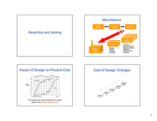
- 1. 1 1 Assembly and Joining 2 Manufacture Unit Manufacturing Processes Unit Manufacturing Processes Assembly and Joining Assembly and Joining Market Research Factory, Systems & Enterprise •Welding •Bolting •Bonding •Soldering •Machining •Injection molding •Rapid prototyping •Stamping •Chemical vapor deposition Conceptual Design Design for Manufacture 3 Impact of Design on Product Cost The majority of cost commitment is made early in the product design cycle. Cost in Percent Conception Validation Development Production Operation Time Source:British Aerospace 100 0 10 20 30 40 50 60 70 80 90 85% 95% 5% 20% Committed Spent 4 Cost of Design Changes CONCEPT DESIGN X 10X TOOLING TESTING 100X 1000X RELEASE 10,000X
- 2. 2 5 “The best design is the simplest one that works” Albert Einstein 6 Assembly and Joining • Assembly as a mfg process – Process components – Cost, Quality, Rate and Flexibility • Specific joining processes – Mechanical – Adhesives – Solder and brazing – Cold welding – Fusion welding 7 Assembly statistics 8 Justifying the need/type of assembly •For assembly – Can’t be made in one piece – Functional (bushings, bearings) – Manufacturability – Repair and maintenance – Transport: Does it fit in a plane? •Against assembly – Defects that occur at interfaces – Loss of stiffness – Time & effort – Labor costs – Size
- 3. 3 9 Rough assembly process diagram Material / parts Feeding Orientation Storage Present & fixture Manipulation Transport Joining Curing time Post treatment Joining process Present & fixture Inspection Material / parts 10 Manual vs Automatic Assembly ƒManual assembly • Dexterity • Time (small run, urgent) • Complexity ƒAutomatic assembly • Precision • Load • Time ƒWhat is important • Minimize parts • Ergonomics • Cost • Training • Reliability 11 PART TRANSPORT, ORIENATION AND FEEDING 12 Part handling and feeding ƒ Moving parts between processing stations ƒ Control amount delivered ƒ Control spacing and frequency of delivery ƒ Robust with respect to tangling and jamming
- 4. 4 13 Part transport: Overhead http://www.tegopi.pt/pt/novidades/images/25-10-2000.jpg http://accosystems.com/autoclient%20(2).jpg 14 Part transport: Conveyor http://www.ssiconveyors.com/pics/ http://www.ssiconveyors.com/pics/ 15 Part transport: Transfer line 16 AGV Pallet load / unload mechanism Workpiece Pallet Safeguard s against collision
- 5. 5 17 Part feeding and orientation 18 Part feeding and orientation 19 Part feeding and orientation 20 Part feeding and orientation
- 6. 6 21 Guidelines to Good Design-for-Assembly ƒ Minimize the number of parts ƒ Design assembly process in a layered fashion ƒ Consider ease of part handling ƒ Utilize optimum attachment methods ƒ Consider ease of alignment and insertion ƒ Avoid design features that require adjustments 22 DFA - Example 0.1 0.2 0.3 0.4 0.5 0.6 0.7 0.8 0.9 1.0 0 24 8 4 2 Annual production volumes : robotic - 200,000 automatic - 2,400,000 Assembly cost ($) Number of parts Minimize the number of parts 23 Minimize the number of parts DFA - Example 24 Design assembly process in a layered fashion DFA - Example
- 7. 7 25 Consider ease of part handling DFA - Example 26 Consider ease of part handling DFA - Example 27 Utilize optimum attachment methods DFA - Example 28 Utilize optimum attachment methods 10 20 30 40 50 100 200 0 2 4 6 8 box-end wrench open-end wrench Socket ratchet wrench Nut driver Clearance, mm Run down time / rev, s Clearance Clearance Hex-nut driver Socket ratchet wrench Box-end wrench Open-end wrench DFA - Example
- 8. 8 29 Utilize optimum attachment methods DFA - Example 30 Utilize optimum attachment methods DFA - Example 31 Consider ease of alignment and insertion ƒ Design parts to maintain location DFA - Example 32 Consider ease of alignment and insertion ƒ Mating parts should be easy to align and insert DFA - Example
- 9. 9 33 Consider ease of alignment and insertion DFA - Example 34 Avoid design features that require adjustments DFA - Example 35 Avoid restricted vision DFA - Example 36 Avoid obstructed access DFA - Example
- 10. 10 37 Joining ƒ Assembly cost often account for more than 50% ƒ Joining processes ƒ High scrap cost ƒ Failure spot 38 Joining processes/types 39 Selection Criteria ƒ Geometry ƒ Material type ƒ Value of end product ƒ Size of product run ƒ Availability of joining method 40 MECHANICAL JOINING
- 11. 11 41 Mechanical Fastening ƒ Any shape and material ƒ Semi-permanent ƒ Least expensive for low volume (standardized) ƒ Problems: strength, seal, extra part, assembly, loosen 42 Fasteners • Bolts/screws – Good for disassembly and reassembly – Cross threading can be a problem • Rivets – Used when disassembly is not required • Dowel pins • Cotter pins • Snap fits 43 Elastic Averaging Non-Deterministic Pinned Joints No Unique Position Exact constraint Kinematic Constraint Common alignment mechanisms Contaminants: Sensitive Load capacity: High Wear in: Long Exact constraint: No Cost: $$$ Complexity: Simple Common: Yes Repeatability ~ 5 micron after wear in Contaminants: Insensitive Load capacity: Low - High Wear in: No Exact constraint: No Cost: $ <-> $$$ Complexity: Simple Common: Yes Repeatability ~ 25 micron at best Contaminants: Insensitive Load capacity: Low - High Wear in: Short Exact constraint: Yes Cost: $$ Complexity: Moderate Common: No Repeatability ~ ¼ micron is common Relative cost: $ = low cost $$ = moderate cost $$$ = expensive 44 Embossing and hemming • Embossed protrusions – Plastic deformation / interference – Appliances – Automotive – Furniture • Hemming – Bend edge of one component over another – Automobile doors
- 12. 12 45 Press fits ( ) ( ) ( ) ⎥ ⎦ ⎤ ⎢ ⎣ ⎡ − ⋅ ⋅ − ⋅ − ⋅ ⋅ = i o i o r r R r R R r R E p 2 2 2 2 2 2 2 2 δ ro R ri insert insert x R p F ⋅ ⋅ ⋅ ⋅ ⋅ = π µ 2 T R thermal ∆ ⋅ ⋅ =α δ δ = radial interference α = Coefficient of thermal expansion E = Young’s modulus ∆T = Temperature change p = interface pressure Insertion force for press fit 0 500 1000 1500 2000 2500 3000 0.00 0.05 0.10 0.15 0.20 0.25 Press Depth, in Press Force, lbf 46 ADHESIVE JOINING 47 Example – Adhesive Bonding 48 Adhesive joining • Advantages – Different materials, Easily automated, Damp /seal • Limitations – Time, Preparation/curing, Loading • Important properties/characteristics of adhesives – Strength, Chemically inert, Compatibility
- 13. 13 49 Adhesive Bonding ƒ Quick, non-invasive, inexpensive ƒ Low stress ƒ Variety of materials ƒ Seal ƒ Low part count ƒ Temperature-limited ƒ Long set time ƒ Surface preparation ƒ Reliability/disassembly ƒ Best for components with high surface to volume ratio 50 Stefan Equation u y r a h/2 h/2 F ⎥ ⎥ ⎦ ⎤ ⎢ ⎢ ⎣ ⎡ − = 2 2 4 1 1 4 3 i f h h a Ft µπ 51 What does Stephan equation mean? ⎟ ⎟ ⎠ ⎞ ⎜ ⎜ ⎝ ⎛ ⋅ ⋅ ⋅ ⋅ ≈ ⋅ 2 4 1 4 3 final final h a t F π µ Viscosity: Start with low µ & finish with high µ Gap: Small assembled gap 52 DFM with adhesives • What is important – Matching type of loading to the design (shear/tension vs. peeling) – Maximizing contact area Poor Good Poor Good Poor Good
- 14. 14 53 BRAZING & SOLDERING 54 Example – Brazing / Soldering 55 Soldering/Brazing ƒ Capillary ƒ Shear strength ƒ Temperature limit • Soldering : < 450 degree : Lead, Tin • Brazing : > 450 degree: Silver, Brass, Bronze ƒ Substrate phase stays solid : can be used on dissimilar metals ƒ Used in electronics, plumbing, jewelry, and recently, as a structural joining 56 Soldering & brazing • Brazing: T > 450o C – Brazes: Silver, Brass, Bronze • Soldering: T < 450o C – Low temps require fluxes – Solders: Lead, Tin, Bismuth • Processes – Torch: Oxyacetylene torch and filler metal – Furnace: Lay filler around joint and send into furnace – Induction: Heat part by induction – Resistance: Heat part by contact/current
- 15. 15 57 Anatomy of solder/brazing process •Purpose of fluxes – Remove oxides – Protect from oxidization – Improve surface wetting •Process – A. Flux on top of oxidized metal – B. Boiling flux removes oxide – C. Base metal in contact with molten flux – D. Molten solder displaces molten flux – E. Solder adheres to base metal – F. Solder solidifies 58 DFA for Soldering and Brazing ƒ Provide large surface area contact ƒ Filler metal should have good wetting characteristics (capillary action) ƒ Joined surfaces should not be smooth 59 COLD WELDING (Interatomic) PROCESSES 60 Ultrasonic and friction welding • Ultrasonic welding (shear @ 10 to 75kHz vibration) – Contamination is redistributed, not displaced – Example: Wires/connectors in electronics components • Friction welding – Material surfaces sheared against each other – Some metal extrudes out of weld zone, removes contaminates
- 16. 16 61 Diffusion bonding • Diffusion bonding is often divided into three stages – Asperities + pressure = decreased interface porosity – Continued heating causes the porosities to shrink – Crystals grow across interface, some porosity may be trapped • Time: Important variables/parameters: – Pressure = (500 to 5,000 psi) Temperature (2/3 Tmelt) – Surface finish Surface cleanliness 62 FUSION WELDING PHYSICS 63 Example – Spot Welding 64 • Process of fusing two materials to join them • Challenges in fusion welding – Disrupting oxide layers and contamination – Achieving high % surface area contact Fusion welding
- 17. 17 65 Welding ƒ Heat source ƒ Heat intensity • Control (overmelting/evaporation) • Heat affected zone (HAZ) • Efficiency • Depth/width ratio 66 Heat Intensity ƒ A measure of radiation intensity, W/cm2 ƒ Obviously the more intense the source, the faster the melting ƒ Very difficult to prevent overmelting, therefore automation! 102 103 104 105 106 107 Air/Fuel Gas Flame Electroslag Oxyacetylene Thermit Friction Arc Welding Resistance Welding (Oxygen Cutting) Electron Beam, Laser Beam 67 Heat intensity and interaction time • Heat intensity (in W/cm2) – HI = Power per unit area directed into the welding zone – HI ~103 melting in < 25 seconds – HI ~106 vaporizes metal in µseconds • Propagation of heat in solids: x ~ (α·t)0.5 – x = distance thermal disturbance travels into thick slab – t = elapsed time ρ k cp α Tmelt g/cm3 W/m/K J/g/oC cm^2/s oC oF Aluminum 2.7 200 0.890 0.832 660 1220 Copper 8.9 400 0.385 1.167 1085 1985 1020 steel 7.9 50 0.448 0.141 1500 2732 Delrin 1.4 0.36 1.464 0.002 175 347 68 Weld pool from 2D simplification t J s c k h T T c J a p fs initial melt p a α ρ α 2 ) ( = = − = : as moves front melt The . by given is y diffusivit thermal The . number, Jacob The s
- 18. 18 69 Welding Rate The rate at which the welding device must be moved is governed by: ƒ The Heat Intensity - the greater the intensity, the faster the motion must be to keep the weld pool size, smax, constant ƒ The product, α Ja, The greater it is, the faster the melt front moves 70 Welding Rate (cont.) ƒ In fact, the time at a spot, tmax is given by s2 max/ 2α Ja. Anymore, and you over-melt! ƒ If the weld pool size is d in length, then you must feed at a rate that exceeds d/tmax. Similarly a lower limit. Weld pool size d Vmin = d / tmax 71 • Definitions of Jacob # and thermal diffusivity: • Solidification front moves in “s” direction as: • To maintain constant weld pool depth at s Melting front and welding velocity p c k ⋅ = ρ α fs initial melt p h T T c J − ⋅ = max 2 t J s ⋅ ⋅ ⋅ = α max t d Vweld > 72 Welding Rate (cont.) ƒ For a planar heat source on steel, tm= (5000/H.I.)2 : where H.I. Is the heat intensity in W/cm2. The number 5000 includes the material constant related terms. ƒ Clearly the greater the H.I. The faster the metal melts.
- 19. 19 73 Weld Pool – Heat Source Interaction Time 10-3 10-2 10-1 100 101 102 103 104 105 106 107 108 103 104 105 106 107 108 103 102 101 100 10-1 10-2 10-3 10-4 10-5 10-6 10-7 10-8 Heat Intensity (Watts/cm2) Interaction Rate (Seconds -1 ) Interaction Time (Seconds) Copper, Aluminum Steels, Nickels Uranium, Ceramics Higher α, Ja Main factor : Thermal diffusivity 74 Weld Travel Velocity 102 101 100 10-1 10-2 10-3 10-4 10-5 10-6 10-7 10-8 10-9 103 104 105 106 107 108 109 108 107 106 105 104 103 102 101 100 10-1 10-2 Heat Intensity (Watts/cm2) Heat Source Spot Diameter, dn (cm) Maximum Weld Travel Velocity (cm/s) ) ( max m I I H t t d V • = 75 Heat Affected Zone ƒ Region near the weld pool is affected by heat. Microstructure changes. ƒ The size of the heat affected zone is controlled by the thermal diffusivity, α. s 76 Heat Localization ƒ Why does alpha affect the size of the HAZ? ƒ Lower values of alpha, more localized heating, which is better for welding? ƒ Have you tried taking a soldering iron to plastic? You get small weld pool. But on metal, you heat the whole piece! Heat applied Temperature Increasing α or decreasing α?
- 20. 20 77 FUSION WELDING PROCESSES 78 Oxyfuel gas welding • Air/fuel welding – Low-cost, portable and flexible – Oxidizing and reducing flames 79 General arc welding • Voltage difference between electrode & work piece – Voltage ~ 100 - 500 V – Current ~ 50 – 300 A • Electrode may be consumed 80 Fillers and shielding in arc welding • Filler metals – Adds metal to weld zone – Flux on/in filler cleans/prevents oxidization – Slag protects molten puddle from oxidation • Shielding – Pellets or grains – Gaseous
- 21. 21 81 General resistance welding • High current through weld area (3k – 40k Amps) – Important: contact pressure & weld current & weld time – Simple, reliable fusion processes – Welds often not easy to inspect ( i.e. spot welds ) – Energy in: i2 R t – Energy req’d: ? – Melting requires ~ 1400 J / g for steel 82 Electron beam and laser welding • Electron beam – Uses electrons to transfer energy • Laser welding – Uses photons to transfer energy • Pros and cons – Advantages: Small HAZ – Disadvantages: $$$!, deep welds require careful fixturing 83 FUSION WELDING DEFECTS 84 Typical defects Source: American Welding Society
- 22. 22 85 Porosity and inclusions • Common causes – Trapped gases – Contaminants – Flux particles • Prevention – Pre-heat – Pre-cleaning – Improved shielding 86 Cracks in welds • Usually result from one or combo of: – Temperature gradients and inability of metal to contract during cooling • Prevention – Preheat components or design to minimize stress from thermal shrinking 87 Residual stresses • Residual stresses cause problems – Distortion on welding – Reduce fatigue life • Prevention – Preheating – Stress relieving in furnace (post heating) A B 88 Heat affected zone (HAZ) • Material is not melted, but is heated • Properties in HAZ differ and depend on: – Temperature – Time – Original properties – HI
- 23. 23 89 FUSION WELDING DFM 90 DFM for Welding One-half the weld metal same strength Twice the weld metal - same strength Previous Design 21 Pieces Improved 3 Pieces Design simplicity can save much welding and assembly time 91 DFM for Welding (conti.) Electrode must be held close to 45° when making these fillers Easy to draw, but the 2nd weld will be hard to make Very difficult Easy Easy to specify “weld all around” but ….. Try to avoid placing pipe joints near wall so that one or two sides are inaccesible. These welds must be made with bent electrodes and mirror Too close to side to allow proper electrode positioning. May be OK for average work but bad for leakproof welding Pipe Wall 92 • Cracks open in tension • Most welds are hard, not easily machined • Part preparation DFM for welding
- 24. 24 93 Cost - Joining ƒ Metal arc welding ƒ Low tooling costs, moderate equipment costs ƒ High direct labor costs ƒ Economical for low production runs ƒ Resistance welding ƒ Low tooling costs, high equipment costs ƒ Low direct labor costs ƒ Full automation can be easily formed ƒ Soldering / Brazing ƒ Low tooling costs, various equipment costs depending on the automation level ƒ Low to moderate direct labor costs ƒ Adhesive bonding ƒ Low tooling costs, moderate equipment costs ƒ Low direct labor costs 94 Quality - Joining ƒ Metal arc welding ƒ Relatively moderate HAZ exists ƒ Good surface finish ƒ Resistance welding ƒ Clean, high quality welding with low distortion ƒ Small HAZ ƒ High strength welds are produced by flash welding ƒ Soldering / Brazing ƒ Virtually stress and distortion free joints ƒ Excellent surface finish ƒ Adhesive bonding ƒ Excellent quality joints with virtually no distortion ƒ Joint strength may deteriorate with time and sever environment conditions 95 Rate - Joining ƒ Metal arc welding ƒ Economical for low production runs – manual welding ƒ Well suited to traversing automated and robotic systems ƒ Resistance welding ƒ High production rate is possible due to short weld times ƒ Easy full automation ƒ Soldering / Brazing ƒ High production rates are possible for dip soldering ex>Printed Circuit Boards ƒ Adhesive bonding ƒ Low production runs 96 Flexibility - joining ƒ Metal arc welding ƒ Generally high flexibility but depends on the automation level ƒ Resistance welding ƒ Low flexibility due to high automation level ƒ Soldering / Brazing ƒ Various level of automation is possible ƒ Adhesive bonding ƒ Very flexible process ƒ Can aid weight minimization in critical applications