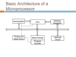
UNIT 1
Microprocessors
What is a Microprocessor?
 Also called as the Brain of the computer.
 It is an integrated circuit that incorporates all the
functions of the Central Processing unit (CPU)
 It is used to perform various arithmetic and logical
operations, stores data and controls the system.
 In 1971, Intel introduced first microprocessor Intel
4004 which was able to perform processing,
transmit data and apply simple mathematical
operations.
 Smart phones, washing machines, microwave
also have microprocessors.
Basic Architecture of a
Microprocessor
Accumulator
Timing and
clock circuit
Program
Counter
Stack Pointer
ALU
Interrupt
Circuit
Working
Registers
Basic Architecture of a
Microprocessor
 ALU(Arithmetic and Logic Unit):
- used to perform arithmetical(+,-,*,/) and
logical(and,or,ex-or,not,ex-nor) operation.
 Accumulator:
- It is used to store the result of the ALU.
 Registers:
- It is used to store data.
- Registers are classified into:
>General Purpose Registers
>Temporary Registers
>Special purpose Registers
Basic Architecture of a
Microprocessor
 Interrupt Control:
- It accepts different types of interrupt request
input. For a valid interrupt request it takes the
necessary actions.
 Timing and Control Unit:
- It provides timing signal(Clock cycles).
- It provides control signals to the system.
 Buses:
- The different types of buses are:
>Data bus: To carry data
>Address bus: To send address of memory
locations
>Control bus: To carry control signals (eg.
Arithmetic and Logical Unit
ALU
Input
Operands
Opcode
Output
Operand
Definitions
 Opcode: Operation that is to be performed in
operands.
 Operands: data on which operations are to be
performed.
 Instruction: combination of opcode and
operands to instruct a system.
 Instruction set: a set of instructions that can be
issued to a system.
 Program/Subroutine/Procedure: Set of
instructions written in a particular order.
Definitions
 Interrupt: It is a mechanism by which an I/O
device(h/w interrupt) or an instruction(s/w
interrupt) can suspend the normal execution of
the processor and get itself serviced.
 Interrupt service routine(ISR): A small program
or a routine that when executed services the
corresponding interrupting source is called as
an ISR.
Definitions
 Vectored/Non-Vectored interrupt: If the ISR
address of the interrupt is to be taken from the
interrupting source itself, then it is called as
non-vectored interrupt; otherwise it is a
vectored interrupt.
 Maskable/Non-maskable interrupt: Interrept
that can be masked(disabled) and
unmasked(enabled) by the programmer is
called as maskable interrupt else it is a non-
maskable interrupt.
Types of Microprocessor:
 There are basically 3 types of
microprocessors:
• Complex Instruction Set Microprocessors.
- consists instruction that perform complex tasks.
- requires large amount of time to execute instructions.
• Reduced Instruction Set Microprocessors.
- work with simple instructions.
- requires less amount of time for execution.
• Superscalar Microprocessors.
- perform number of tasks at the same time.
Application of Microprocessors:
 Microcomputers
 Personal Computers
 Printing Machines
 Security Systems
 Play Stations
 Digital Projectors
 Washing Machines
 Microwave Ovens
Evolution of Microprocessor:
 4-bit microprocessor
- In 1971, Intel Corp. introduced 4-bit microprocessor 4004.
- It had a single chip that can perform arithmetic and logical
operations on 4-bit data.
 8-bit microprocessor
- In 1973, Intel introduced 8-bit microprocessor 8008,8085.
- It can perform arithmetic and logical operations on 4,8 bit
data.
 16-bit microprocessor
- Intel 8086 and 80286.
- can perform arithmetic and logical operations on 4,8
and 16 bit data.
Evolution of Microprocessor:
 32-bit microprocessor:
- Intel 80386.
- Performs arithmetic and logical operations on 4,8,16
and 32 bit data.
 64-bit microprocessor:
- Intel Pentium.
- Performs arithmetic and logical operations on 4,8,16
and 32 bit data.
80386 Microprocessor
 It is a 32-bit microprocessor.
 It has 32-bit registers.
 ALU can operate on 8/16/32 bit data operands.
 It supports physical address of 4GB.
 It supports virtual address of 64TB.
 It operates in 3 different modes : real, protected
and virtual mode.
 The memory management unit provides virtual
memory, paging and segmentation, 4 level of
protection.
 Clock frequency: 20,25, and 35MHz (Clock
cycles/second)
80386 Microprocessor
 80386 is categorized as:
- 80386SX(16bit data bus,24bit address bus, 32bit
registers)
- 80386SL(16bit data bus,24bit address bus, 32bit
registers in addition to bus controller, memory
controller, cache controller)
- 80386DX(16/32bit data bus,32bit address bus,
32bit registers)
- 80386EX(80386DX(16/32bit data bus,32bit
address bus, 32bit registers)
Types of Memory
 Cache Memory
 Primary Memory
 Secondary Memory
Cache Memory
- Cache memory is a extremely high speed
memory that can speed up CPU operation.
- It is used to access data/instructions that are
most regularly used by CPU.
- Quick access to these data/instructions will
speed up the software program.
- It stores data for temporary use.
Primary Memory
- RAM(Random Access Memory) accesses
memory locations randomly.
- Volatile memory – means data will be lost
when power is off.
- Faster than secondary memory.
- Two types of RAM:
> Static RAM (SRAM)
> Dynamic RAM (DRAM)
SRAM Vs DRAM
SRAM(Static RAM) DRAM(Dynamic RAM)
SRAM uses flip flops DRAM uses capacitors.
No refreshing required Continuous refreshing
required to retain data
Faster data access Slower access to data
More space as more
number of components
required.
Less space as less
number of components
are required.
Costly Cheaper
Used as Cache memory Used as Main Memory
Secondary Memory
- ROM (Read Only Memory)
- Non-volatile memory- retains data
- cheaper than RAM
- eg. Hard disks, CD/DVD etc.
Secondary Memory
Types of ROM:
> PROM (programmable read only
memory)
- written only once, cannot be re-
written.
> EPROM (Erasable programmable ROM)
- can be erased with UV Rays and can
be re-written.
> EEPROM ( Electronically Erasable
Architecture of 80386DX
 Architecture of 80386DX is divided into:
- Central Processing Unit (CPU)
- Memory Management Unit (MMU)
- Bus Interface Unit (BIU)
Architecture of 80386DX
Central Processing Unit
 Central Processing Unit has:
- Execution Unit
- Instruction Unit
 Task of CPU is to fetch instruction, decode it
and execute the given instruction.
Execution Unit
 Execution Unit has:
- 8 general purpose registers
- 8 special purpose registers
- These registers will be used either to store
data or calculate offset addresses.
- Execution unit is used to execute instructions
from Instruction unit.
Instruction Unit
 Instruction unit has:
- Prefetch unit
- Decode unit
 Instruction Prefetch unit is used to fetch
instructions in advance. It will store next
instructions to be executed in prefetch queue.
 Instruction Decode unit is used to decode the
prefetched instruction and will store the
decoded instruction in Decoded instruction
queue.
Central Processing Unit
 When Execution unit is executing the current
instruction the prefetch unit fetches the next
16B instructions and stores in it Prefetch
queue.
 The execution of program needs arithmetic
and logical operations performed by the ALU.
 Operands for the ALU come from the Register
File – General Purpose registers.
 Execution unit has 32 bit flag register used to
give the status of the result.
 Protection test unit gives protection to
programs based on their privileges.
Memory Management Unit
 Memory Management unit consists of:
- Segmentation Unit
- Paging Unit
 Segmentation unit:
- divides memory into different segments.
- maximum segment size is of 4GB.
 Paging unit:
- divides memory in terms of pages.
- Page size is 4KB
- works under control of segmentation unit. i.e.
segments are divided into pages.
Bus Interface Unit
 Bus Interface unit has:
- Request Prioritizer: resolve the priorities of
various bus request. It will control the access
to a bus.
- Address Driver: provides addresses
- Pipeline and transreceiver will receive
different instructions and store it in pipeline.
Register Organization
 Memory locations inside the processor are
nothing but the registers.
 There are two types of registers:
- User registers: used for user applications.
- System registers: used by the operating
system.
Register Organization of 80386
General Purpose Registers
 It holds the operands of an instruction on
which operation is to be performed.
 80386 has 8 32-bit registers that can be used
as either 8/16/32 bit registers.
 32-bit registers are known as extended
registers. (prefix E)
 EAX,EBX,ECX,EDX,EBP,ESP,ESI and EDI
are general purpose registers.
Segment registers
 These are 16-bit registers that hold the base
address of a segment:
- CS: Base address of code segment
- DS: Base address of data segment
- ES,FS,GS: Base address of data segment
- SS: Base address of stack segment.
Instruction Pointer and Flag
Register
 EIP:
- 32-bit register that contains memory offset of
the next instruction.
 Flag register:
- 32-bit flag register is used to give the status
of the result of the operation performed by the
ALU.
Flag register
Flag register
 Carry flag (CF):
- 1 if operation results in a carry.
- 0 otherwise
 Parity flag (PF):
- 1 if result contains even number of 1’s
- 0 otherwise
 Auxilliary Flag (AF):
- 1 if there is a carry from 3rd
bit to 4th
bit
- 0 otherwise
Flag register
 Zero flag (ZF)
- 1 is result is 0
- 0 otherwise
 Sign Flag (SF)
- 1 is result of the operation is negative
- 0 otherwise
 Trap Flag (TF)
- 1 if it operates in single step mode.
- 0 otherwise
Flag register
 Interrupt enabled Flag (IF):
- 1 means interrupts from devices are allowed
- 0 means interrupts are ignored
 Direction Flag (DF):
- 1 means it is a string operation
- 0 otherwise
 Input/Output Privilege level (IOPL):
- 2 bit field to set privilege to the instructions to
be executed.
Flag register
 Nested Flag (NF):
- 1 means current instruction is a nested
instruction
- 0 otherwise
 Resume Flag (RF):
- 1 at starting execution of every instruction.
- 0 no execution
 Virtual mode Flag (VM):
- 1 processor operating in virtual mode
- 0 normal mode
System Registers
 Segment Descriptor registers:
- stores information about the segments.
 Control Registers: CR0,CR2,CR3
- control overall system operations.
 System address registers:
- stores address of descriptor tables
 Debug and Test registers: DR0-DR7
- used when debugging programs.
Operating Modes in 80386
 Protected Mode
 Real Address Mode
 Virtual Address Mode
Machine Cycle
 Fetch
- get instruction from the memory
 Decode
- interpret/understand the instruction
 Execute
- execute/run the instruction
 Store
- store result of the execution
Signal in 80386
 CLK: provides clock timing to the processor
 D0-D31: data transmission
 A2-A31: address transmission
 Ready: indicates previous cycle is finished and ready for
next cycle
 VCC: power supply
 ERROR: error in execution
 INTR: interrupt request
 INTA: interrupt acknowledgement
 NMI: non-maskable interrupt
 Reset: reset processor settings

Microprocessors - 80386DX

  • 1.
  • 2.
    What is aMicroprocessor?  Also called as the Brain of the computer.  It is an integrated circuit that incorporates all the functions of the Central Processing unit (CPU)  It is used to perform various arithmetic and logical operations, stores data and controls the system.  In 1971, Intel introduced first microprocessor Intel 4004 which was able to perform processing, transmit data and apply simple mathematical operations.  Smart phones, washing machines, microwave also have microprocessors.
  • 3.
    Basic Architecture ofa Microprocessor Accumulator Timing and clock circuit Program Counter Stack Pointer ALU Interrupt Circuit Working Registers
  • 4.
    Basic Architecture ofa Microprocessor  ALU(Arithmetic and Logic Unit): - used to perform arithmetical(+,-,*,/) and logical(and,or,ex-or,not,ex-nor) operation.  Accumulator: - It is used to store the result of the ALU.  Registers: - It is used to store data. - Registers are classified into: >General Purpose Registers >Temporary Registers >Special purpose Registers
  • 5.
    Basic Architecture ofa Microprocessor  Interrupt Control: - It accepts different types of interrupt request input. For a valid interrupt request it takes the necessary actions.  Timing and Control Unit: - It provides timing signal(Clock cycles). - It provides control signals to the system.  Buses: - The different types of buses are: >Data bus: To carry data >Address bus: To send address of memory locations >Control bus: To carry control signals (eg.
  • 6.
    Arithmetic and LogicalUnit ALU Input Operands Opcode Output Operand
  • 7.
    Definitions  Opcode: Operationthat is to be performed in operands.  Operands: data on which operations are to be performed.  Instruction: combination of opcode and operands to instruct a system.  Instruction set: a set of instructions that can be issued to a system.  Program/Subroutine/Procedure: Set of instructions written in a particular order.
  • 8.
    Definitions  Interrupt: Itis a mechanism by which an I/O device(h/w interrupt) or an instruction(s/w interrupt) can suspend the normal execution of the processor and get itself serviced.  Interrupt service routine(ISR): A small program or a routine that when executed services the corresponding interrupting source is called as an ISR.
  • 9.
    Definitions  Vectored/Non-Vectored interrupt:If the ISR address of the interrupt is to be taken from the interrupting source itself, then it is called as non-vectored interrupt; otherwise it is a vectored interrupt.  Maskable/Non-maskable interrupt: Interrept that can be masked(disabled) and unmasked(enabled) by the programmer is called as maskable interrupt else it is a non- maskable interrupt.
  • 10.
    Types of Microprocessor: There are basically 3 types of microprocessors: • Complex Instruction Set Microprocessors. - consists instruction that perform complex tasks. - requires large amount of time to execute instructions. • Reduced Instruction Set Microprocessors. - work with simple instructions. - requires less amount of time for execution. • Superscalar Microprocessors. - perform number of tasks at the same time.
  • 11.
    Application of Microprocessors: Microcomputers  Personal Computers  Printing Machines  Security Systems  Play Stations  Digital Projectors  Washing Machines  Microwave Ovens
  • 12.
    Evolution of Microprocessor: 4-bit microprocessor - In 1971, Intel Corp. introduced 4-bit microprocessor 4004. - It had a single chip that can perform arithmetic and logical operations on 4-bit data.  8-bit microprocessor - In 1973, Intel introduced 8-bit microprocessor 8008,8085. - It can perform arithmetic and logical operations on 4,8 bit data.  16-bit microprocessor - Intel 8086 and 80286. - can perform arithmetic and logical operations on 4,8 and 16 bit data.
  • 13.
    Evolution of Microprocessor: 32-bit microprocessor: - Intel 80386. - Performs arithmetic and logical operations on 4,8,16 and 32 bit data.  64-bit microprocessor: - Intel Pentium. - Performs arithmetic and logical operations on 4,8,16 and 32 bit data.
  • 14.
    80386 Microprocessor  Itis a 32-bit microprocessor.  It has 32-bit registers.  ALU can operate on 8/16/32 bit data operands.  It supports physical address of 4GB.  It supports virtual address of 64TB.  It operates in 3 different modes : real, protected and virtual mode.  The memory management unit provides virtual memory, paging and segmentation, 4 level of protection.  Clock frequency: 20,25, and 35MHz (Clock cycles/second)
  • 15.
    80386 Microprocessor  80386is categorized as: - 80386SX(16bit data bus,24bit address bus, 32bit registers) - 80386SL(16bit data bus,24bit address bus, 32bit registers in addition to bus controller, memory controller, cache controller) - 80386DX(16/32bit data bus,32bit address bus, 32bit registers) - 80386EX(80386DX(16/32bit data bus,32bit address bus, 32bit registers)
  • 16.
    Types of Memory Cache Memory  Primary Memory  Secondary Memory
  • 17.
    Cache Memory - Cachememory is a extremely high speed memory that can speed up CPU operation. - It is used to access data/instructions that are most regularly used by CPU. - Quick access to these data/instructions will speed up the software program. - It stores data for temporary use.
  • 18.
    Primary Memory - RAM(RandomAccess Memory) accesses memory locations randomly. - Volatile memory – means data will be lost when power is off. - Faster than secondary memory. - Two types of RAM: > Static RAM (SRAM) > Dynamic RAM (DRAM)
  • 19.
    SRAM Vs DRAM SRAM(StaticRAM) DRAM(Dynamic RAM) SRAM uses flip flops DRAM uses capacitors. No refreshing required Continuous refreshing required to retain data Faster data access Slower access to data More space as more number of components required. Less space as less number of components are required. Costly Cheaper Used as Cache memory Used as Main Memory
  • 20.
    Secondary Memory - ROM(Read Only Memory) - Non-volatile memory- retains data - cheaper than RAM - eg. Hard disks, CD/DVD etc.
  • 21.
    Secondary Memory Types ofROM: > PROM (programmable read only memory) - written only once, cannot be re- written. > EPROM (Erasable programmable ROM) - can be erased with UV Rays and can be re-written. > EEPROM ( Electronically Erasable
  • 22.
  • 23.
    Architecture of 80386DX Architecture of 80386DX is divided into: - Central Processing Unit (CPU) - Memory Management Unit (MMU) - Bus Interface Unit (BIU)
  • 24.
  • 25.
    Central Processing Unit Central Processing Unit has: - Execution Unit - Instruction Unit  Task of CPU is to fetch instruction, decode it and execute the given instruction.
  • 26.
    Execution Unit  ExecutionUnit has: - 8 general purpose registers - 8 special purpose registers - These registers will be used either to store data or calculate offset addresses. - Execution unit is used to execute instructions from Instruction unit.
  • 27.
    Instruction Unit  Instructionunit has: - Prefetch unit - Decode unit  Instruction Prefetch unit is used to fetch instructions in advance. It will store next instructions to be executed in prefetch queue.  Instruction Decode unit is used to decode the prefetched instruction and will store the decoded instruction in Decoded instruction queue.
  • 28.
    Central Processing Unit When Execution unit is executing the current instruction the prefetch unit fetches the next 16B instructions and stores in it Prefetch queue.  The execution of program needs arithmetic and logical operations performed by the ALU.  Operands for the ALU come from the Register File – General Purpose registers.  Execution unit has 32 bit flag register used to give the status of the result.  Protection test unit gives protection to programs based on their privileges.
  • 29.
    Memory Management Unit Memory Management unit consists of: - Segmentation Unit - Paging Unit  Segmentation unit: - divides memory into different segments. - maximum segment size is of 4GB.  Paging unit: - divides memory in terms of pages. - Page size is 4KB - works under control of segmentation unit. i.e. segments are divided into pages.
  • 30.
    Bus Interface Unit Bus Interface unit has: - Request Prioritizer: resolve the priorities of various bus request. It will control the access to a bus. - Address Driver: provides addresses - Pipeline and transreceiver will receive different instructions and store it in pipeline.
  • 31.
    Register Organization  Memorylocations inside the processor are nothing but the registers.  There are two types of registers: - User registers: used for user applications. - System registers: used by the operating system.
  • 32.
  • 33.
    General Purpose Registers It holds the operands of an instruction on which operation is to be performed.  80386 has 8 32-bit registers that can be used as either 8/16/32 bit registers.  32-bit registers are known as extended registers. (prefix E)  EAX,EBX,ECX,EDX,EBP,ESP,ESI and EDI are general purpose registers.
  • 34.
    Segment registers  Theseare 16-bit registers that hold the base address of a segment: - CS: Base address of code segment - DS: Base address of data segment - ES,FS,GS: Base address of data segment - SS: Base address of stack segment.
  • 35.
    Instruction Pointer andFlag Register  EIP: - 32-bit register that contains memory offset of the next instruction.  Flag register: - 32-bit flag register is used to give the status of the result of the operation performed by the ALU.
  • 36.
  • 37.
    Flag register  Carryflag (CF): - 1 if operation results in a carry. - 0 otherwise  Parity flag (PF): - 1 if result contains even number of 1’s - 0 otherwise  Auxilliary Flag (AF): - 1 if there is a carry from 3rd bit to 4th bit - 0 otherwise
  • 38.
    Flag register  Zeroflag (ZF) - 1 is result is 0 - 0 otherwise  Sign Flag (SF) - 1 is result of the operation is negative - 0 otherwise  Trap Flag (TF) - 1 if it operates in single step mode. - 0 otherwise
  • 39.
    Flag register  Interruptenabled Flag (IF): - 1 means interrupts from devices are allowed - 0 means interrupts are ignored  Direction Flag (DF): - 1 means it is a string operation - 0 otherwise  Input/Output Privilege level (IOPL): - 2 bit field to set privilege to the instructions to be executed.
  • 40.
    Flag register  NestedFlag (NF): - 1 means current instruction is a nested instruction - 0 otherwise  Resume Flag (RF): - 1 at starting execution of every instruction. - 0 no execution  Virtual mode Flag (VM): - 1 processor operating in virtual mode - 0 normal mode
  • 41.
    System Registers  SegmentDescriptor registers: - stores information about the segments.  Control Registers: CR0,CR2,CR3 - control overall system operations.  System address registers: - stores address of descriptor tables  Debug and Test registers: DR0-DR7 - used when debugging programs.
  • 42.
    Operating Modes in80386  Protected Mode  Real Address Mode  Virtual Address Mode
  • 43.
    Machine Cycle  Fetch -get instruction from the memory  Decode - interpret/understand the instruction  Execute - execute/run the instruction  Store - store result of the execution
  • 44.
    Signal in 80386 CLK: provides clock timing to the processor  D0-D31: data transmission  A2-A31: address transmission  Ready: indicates previous cycle is finished and ready for next cycle  VCC: power supply  ERROR: error in execution  INTR: interrupt request  INTA: interrupt acknowledgement  NMI: non-maskable interrupt  Reset: reset processor settings