SlideShare a Scribd company logo
1 of 228
Download to read offline
MCA 202/MS 11
Author: Abhishek Taneja Vetter: Sh. Dharminder Kumar
Lesson: Introduction Lesson No. : 01
Structure
1.0 Objectives
1.1 Introduction
1.2 Data Processing Vs. Data Management Systems
1.3 File Oriented Approach
1.4 Database Oriented Approach to Data Management
1.5 Characteristics of Database
1.6 Advantages and Disadvantages of a DBMS
1.7 Instances and Schemas
1.8 Data Models
1.9 Database Languages
1.9 Data Dictionary
1.11 Database Administrators and Database Users
1.12 DBMS Architecture and Data Independence
1.13 Types of Database System
1.14 Summary
1.15 keywords
1.16 Self Assessment Questions (SAQ)
1.17 References/Suggested Readings
1.0 Objectives
At the end of this chapter the reader will be able to:
• Distinguish between data and information and Knowledge
• Distinguish between file processing system and DBMS
• Describe DBMS its advantages and disadvantages
• Describe Database users including data base administrator
• Describe data models, schemas and instances.
• Describe DBMS Architecture & Data Independence
• Describe Data Languages
1
1.1 Introduction
A database-management system (DBMS) is a collection of interrelated data and a set of
programs to access those data. This is a collection of related data with an implicit
meaning and hence is a database. The collection of data, usually referred to as the
database, contains information relevant to an enterprise. The primary goal of a DBMS is
to provide a way to store and retrieve database information that is both convenient and
efficient. By data, we mean known facts that can be recorded and that have implicit
meaning. For example, consider the names, telephone numbers, and addresses of the
people you know. You may have recorded this data in an indexed address book, or you
may have stored it on a diskette, using a personal computer and software such as DBASE
IV or V, Microsoft ACCESS, or EXCEL. A datum – a unit of data – is a symbol or a set
of symbols which is used to represent something. This relationship between symbols and
what they represent is the essence of what we mean by information. Hence, information
is interpreted data – data supplied with semantics. Knowledge refers to the practical use
of information. While information can be transported, stored or shared without many
difficulties the same can not be said about knowledge. Knowledge necessarily involves a
personal experience. Referring back to the scientific experiment, a third person reading
the results will have information about it, while the person who conducted the experiment
personally will have knowledge about it.
Database systems are designed to manage large bodies of information. Management of
data involves both defining structures for storage of information and providing
mechanisms for the manipulation of information. In addition, the database system must
ensure the safety of the information stored, despite system crashes or attempts at
unauthorized access. If data are to be shared among several users, the system must avoid
possible anomalous results.
Because information is so important in most organizations, computer scientists have
developed a large body of concepts and techniques for managing data. These concepts
and technique form the focus of this book. This chapter briefly introduces the principles
of database systems.
2
1.2 Data Processing Vs. Data Management Systems
Although Data Processing and Data Management Systems both refer to functions that
take raw data and transform it into usable information, the usage of the terms is very
different. Data Processing is the term generally used to describe what was done by large
mainframe computers from the late 1940's until the early 1980's (and which continues to
be done in most large organizations to a greater or lesser extent even today): large
volumes of raw transaction data fed into programs that update a master file, with fixed-
format reports written to paper.
The term Data Management Systems refers to an expansion of this concept, where the
raw data, previously copied manually from paper to punched cards, and later into data-
entry terminals, is now fed into the system from a variety of sources, including ATMs,
EFT, and direct customer entry through the Internet. The master file concept has been
largely displaced by database management systems, and static reporting replaced or
augmented by ad-hoc reporting and direct inquiry, including downloading of data by
customers. The ubiquity of the Internet and the Personal Computer have been the driving
force in the transformation of Data Processing to the more global concept of Data
Management Systems.
1.3 File Oriented Approach
The earliest business computer systems were used to process business records and
produce information. They were generally faster and more accurate than equivalent
manual systems. These systems stored groups of records in separate files, and so they
were called file processing systems. In a typical file processing systems, each
department has its own files, designed specifically for those applications. The department
itself working with the data processing staff, sets policies or standards for the format and
maintenance of its files.
Programs are dependent on the files and vice-versa; that is, when the physical format of
the file is changed, the program has also to be changed. Although the traditional file
oriented approach to information processing is still widely used, it does have some very
important disadvantages.
1.4 Database Oriented Approach to Data Management
3
Consider part of a savings-bank enterprise that keeps information about all customers and
savings accounts. One way to keep the information on a computer is to store it in
operating system files. To allow users to manipulate the information, the system has a
number of application programs that manipulate the files, including
A program to debit or credit an account
A program to add a new account
A program to find the balance of an account
A program to generate monthly statements
System programmers wrote these application programs to meet the needs of the bank.
New application programs are added to the system as the need arises. For example,
suppose that the savings bank decides to offer checking accounts. As a result, the bank
creates new permanent files that contain information about all the checking accounts
maintained in the bank, and it may have to write new application programs to deal with
situations that do not arise in savings accounts, such as overdrafts. Thus, as time goes by,
the system acquires more files and more application programs.
This typical file-processing system is supported by a conventional operating system. The
system stores permanent records in various files, and it needs different application
programs to extract records from, and add records to, the appropriate files. Before
database management systems (DBMSs) came along, organizations usually stored
information in such systems.
Keeping organizational information in a file-processing system has a number of major
disadvantages:
Data redundancy and inconsistency.
Since different programmers create the files and application programs over a long
period, the various files are likely to have different formats and the programs may be
written in several programming languages. Moreover, the same information may be
duplicated in several places (files). For example, the address and telephone number of a
particular customer may appear in a file that consists of savings-account records and in a
file that consists of checking-account records. This redundancy leads to higher storage
and access cost. In addition, it may lead to data inconsistency; that is, the various copies
4
of the same data may no longer agree. For example, a changed customer address may be
reflected in savings-account records but not elsewhere in the system.
Difficulty in accessing data.
Suppose that one of the bank officers needs to find out the names of all customers who
live within a particular postal-code area. The officer asks the data-processing department
to generate such a list. Because the designers of the original system did not anticipate this
request, there is no application program on hand to meet it. There is, however, an
application program to generate the list of all customers. The bank officer has now two
choices: either obtain the list of all customers and extract the needed information
manually or ask a system programmer to write the necessary application program. Both
alternatives are obviously unsatisfactory. Suppose that such a program is written, and
that, several days later, the same officer needs to trim that list to include only those
customers who have an account balance of $10,000 or more. As expected, a program to
generate such a list does not exist. Again, the officer has the preceding two options,
neither of which is satisfactory.
The point here is that conventional file-processing environments do not allow needed
data to be retrieved in a convenient and efficient manner. More responsive data-retrieval
systems are required for general use.
Data isolation. Because data are scattered in various files, and files may be in different
formats, writing new application programs to retrieve the appropriate data is difficult.
Integrity problems. The data values stored in the database must satisfy certain types of
consistency constraints. For example, the balance of a bank account may never fall
below a prescribed amount (say, $25). Developers enforce these constraints in the system
by adding appropriate code in the various application programs. However, when new
constraints are added, it is difficult to change the programs to enforce them. The problem
is compounded when constraints involve several data items from different files.
Atomicity problems. A computer system, like any other mechanical or electrical
device, is subject to failure. In many applications, it is crucial that, if a failure occurs, the
data be restored to the consistent state that existed prior to the failure. Consider a program
to transfer $50 from account A to account B. If a system failure occurs during the
execution of the program, it is possible that the $50 was removed from account A but was
5
not credited to account B, resulting in an inconsistent database state. Clearly, it is
essential to database consistency that either both the credit and debit occur, or that neither
occur. That is, the funds transfer must be atomic—it must happen in its entirety or not at
all. It is difficult to ensure atomicity in a conventional file-processing system.
Concurrent-access anomalies. For the sake of overall performance of the system
and faster response, many systems allow multiple users to update the data
simultaneously. In such an environment, interaction of concurrent updates may result in
inconsistent data. Consider bank account A, containing $500. If two customers withdraw
funds (say $50 and $100 respectively) from account A at about the same time, the result
of the concurrent executions may leave the account in an incorrect (or inconsistent) state.
Suppose that the programs executing on behalf of each withdrawal read the old balance,
reduce that value by the amount being withdrawn, and write the result back. If the two
programs run concurrently, they may both read the value $500, and write back $450 and
$400, respectively. Depending on which one writes the value last, the account may
contain either $450 or $400, rather than the correct value of $350. To guard against this
possibility, the system must maintain some form of supervision. But supervision is
difficult to provide because data may be accessed by many different application programs
that have not been coordinated previously.
Security problems. Not every user of the database system should be able to access all
the data. For example, in a banking system, payroll personnel need to see only that part of
the database that has information about the various bank employees. They do not need
access to information about customer accounts. But, since application programs are
added to the system in an ad hoc manner, enforcing such security constraints is difficult.
These difficulties, among others, prompted the development of database systems. In what
follows, we shall see the concepts and algorithms that enable database systems to solve
the problems with file-processing systems. In most of this book, we use a bank enterprise
as a running example of a typical data-processing application found in a corporation.
1.5 Characteristics of Database
The database approach has some very characteristic features which are discussed in detail
below:
6
1.5.1 Concurrent Use
A database system allows several users to access the database concurrently. Answering
different questions from different users with the same (base) data is a central aspect of an
information system. Such concurrent use of data increases the economy of a system.
An example for concurrent use is the travel database of a bigger travel agency. The
employees of different branches can access the database concurrently and book journeys
for their clients. Each travel agent sees on his interface if there are still seats available for
a specific journey or if it is already fully booked.
1.5.2 Structured and Described Data
A fundamental feature of the database approach is that the database systems does not
only contain the data but also the complete definition and description of these data. These
descriptions are basically details about the extent, the structure, the type and the format of
all data and, additionally, the relationship between the data. This kind of stored data is
called metadata ("data about data").
1.5.3 Separation of Data and Applications
As described in the feature structured data the structure of a database is described through
metadata which is also stored in the database. An application software does not need any
knowledge about the physical data storage like encoding, format, storage place, etc. It
only communicates with the management system f a database (DBMS) via a standardised
interface with the help of a standardised language like SQL. The access to the data and
the metadata is entirely done by the DBMS. In this way all the applications can be totally
seperated from the data. Therefore database internal reorganisations or improvement of
efficiency do not have any influence on the application software.
1.5.4 Data Integrity
Data integrity is a byword for the quality and the reliability of the data of a database
system. In a broader sense data integrity includes also the protection of the database from
unauthorised access (confidentiality) and unauthorised changes. Data reflect facts of the
real world. database.
1.5.5 Transactions
A transaction is a bundle of actions which are done within a database to bring it from one
7
consistent state to a new consistent state. In between the data are inevitable inconsistent.
A transaction is atomic what means that it cannot be divided up any further. Within a
transaction all or none of the actions need to be carried out. Doing only a part of the
actions would lead to an inconsistent database state. One example of a transaction is the
transfer of an amount of money from one bank account to another. The debit of the
money from one account and the credit of it to another account makes together a
consistent transaction. This transaction is also atomic. The debit or credit alone would
both lead to an inconsistent state. After finishing the transaction (debit and credit) the
changes to both accounts become persistent and the one who gave the money has now
less money on his account while the receiver has now a higher balance.
1.5.6 Data Persistence
Data persistence means that in a DBMS all data is maintained as long as it is not deleted
explicitly. The life span of data needs to be determined directly or indirectly be the user
and must not be dependent on system features. Additionally data once stored in a
database must not be lost. Changes of a database which are done by a transaction are
persistent. When a transaction is finished even a system crash cannot put the data in
danger.
1.6 Advantages and Disadvantages of a DBMS
Using a DBMS to manage data has many advantages:
Data independence: Application programs should be as independent as possible from
details of data representation and storage. The DBMS can provide an abstract view of the
data to insulate application code from such details.
Efficient data access: A DBMS utilizes a variety of sophisticated techniques to store and
retrieve data efficiently. This feature is especially important if the data is stored on
external storage devices.
Data integrity and security: If data is always accessed through the DBMS, the DBMS
can enforce integrity constraints on the data. For example, before inserting salary
information for an employee, the DBMS can check that the department budget is not
exceeded. Also, the DBMS can enforce access controls that govern what data is visible to
different classes of users.
8
Data administration: When several users share the data, centralizing the administration
of data can offer significant improvements. Experienced professionals who understand
the nature of the data being managed, and how different groups of users use it, can be
responsible for organizing the data representation to minimize redundancy and fine-
tuning the storage of the data to make retrieval efficient.
Concurrent access and crash recovery: A DBMS schedules concurrent accesses to the
data in such a manner that users can think of the data as being accessed by only one user
at a time. Further, the DBMS protects users from the effects of system failures.
Reduced application development time: Clearly, the DBMS supports many important
functions that are common to many applications accessing data stored in the DBMS.
This, in conjunction with the high-level interface to the data, facilitates quick
development of applications. Such applications are also likely to be more robust than
applications developed from scratch because many important
tasks are handled by the DBMS instead of being implemented by the application. Given
all these advantages, is there ever a reason not to use a DBMS? A DBMS is a complex
piece of software, optimized for certain kinds of workloads (e.g., answering complex
queries or handling many concurrent requests), and its performance may not be adequate
for certain specialized applications. Examples include applications with tight real-time
constraints or applications with just a few well-designed critical operations for which
efficient custom code must be written. Another reason for not using a DBMS is that an
application may need to manipulate the data in ways not supported by the query
language. In such a situation, the abstract view of the data presented by the DBMS does
not match the application's needs, and actually gets in the way. As an example, relational
databases do not support flexible analysis of text data (although vendors are now
extending their products in this direction). If specialized performance or data
manipulation requirements are central to an application, the application may choose not
to use a DBMS, especially if the added benefits of a DBMS (e.g., flexible querying,
security, concurrent access, and crash recovery) are not required. In most situations
calling for large-scale data management, however, DBMSs have become an
indispensable tool.
9
Disadvantages of a DBMS
Danger of a Overkill: For small and simple applications for single users a database
system is often not advisable.
Complexity: A database system creates additional complexity and requirements. The
supply and operation of a database management system with several users and databases
is quite costly and demanding.
Qualified Personnel: The professional operation of a database system requires
appropriately trained staff. Without a qualified database administrator nothing will work
for long.
Costs: Through the use of a database system new costs are generated for the system
itselfs but also for additional hardware and the more complex handling of the system.
Lower Efficiency: A database system is a multi-use software which is often less efficient
than specialised software which is produced and optimised exactly for one problem.
1.7 Instances and Schemas
Databases change over time as information is inserted and deleted. The collection of
information stored in the database at a particular moment is called an instance of the
database. The overall design of the database is called the database schema. Schemas are
changed infrequently, if at all.
The concept of database schemas and instances can be understood by analogy to a
program written in a programming language. A database schema corresponds to the
variable declarations (along with associated type definitions) in a program. Each variable
has a particular value at a given instant. The values of the variables in a program at a
point in time correspond to an instance of a database schema.
Database systems have several schemas, partitioned according to the levels of
abstraction.
The physical schema describes the database design at the physical level, while the
logical schema describes the database design at the logical level.Adatabase may also
have several schemas at the view level, sometimes called subschemas, that describe
different views of the database.
10
Of these, the logical schema is by far the most important, in terms of its effect on
application programs, since programmers construct applications by using the logical
schema. The physical schema is hidden beneath the logical schema, and can usually be
changed easily without affecting application programs. Application programs are said to
exhibit physical data independence if they do not depend on the physical schema, and
thus need not be rewritten if the physical schema changes.
We study languages for describing schemas, after introducing the notion of data models
in the next section.
1.8 Data Models
Underlying the structure of a database is the data model: a collection of conceptual tools
for describing data, data relationships, data semantics, and consistency constraints.
To illustrate the concept of a data model, we outline two data models in this section: the
entity-relationship model and the relational model. Both provide a way to describe the
design of a database at the logical level.
1.8.1 The Entity-Relationship Model
The entity-relationship (E-R) data model is based on a perception of a real world that
consists of a collection of basic objects, called entities, and of relationships among these
objects. An entity is a “thing” or “object” in the real world that is distinguishable from
other objects. For example, each person is an entity, and bank accounts can be considered
as entities.
Entities are described in a database by a set of attributes. For example, the attributes
account-number and balance may describe one particular account in a bank, and they
form attributes of the account entity set. Similarly, attributes customer-name, customer-
street address and customer-city may describe a customer entity.
An extra attribute customer-id is used to uniquely identify customers (since it may be
possible to have two customers with the same name, street address, and city).
A unique customer identifier must be assigned to each customer. In the United States,
many enterprises use the social-security number of a person (a unique number the U.S.
government assigns to every person in the United States) as a customer identifier.
A relationship is an association among several entities. For example, a depositor
relationship associates a customer with each account that she has. The set of all entities of
11
the same type and the set of all relationships of the same type are termed an entity set
and relationship set, respectively.
The overall logical structure (schema) of a database can be expressed graphically by an
E-R diagram.
1.8.2 Relational Model
The relational model uses a collection of tables to represent both data and the
relationships among those data. Each table has multiple columns, and each column has a
unique name.
The data is arranged in a relation which is visually represented in a two dimensional
table. The data is inserted into the table in the form of tuples (which are nothing but
rows). A tuple is formed by one or more than one attributes, which are used as basic
building blocks in the formation of various expressions that are used to derive a
meaningful information. There can be any number of tuples in the table, but all the tuple
contain fixed and same attributes with varying values. The relational model is
implemented in database where a relation is represented by a table, a tuple is represented
by a row, an attribute is represented by a column of the table, attribute name is the name
of the column such as ‘identifier’, ‘name’, ‘city’ etc., attribute value contains the value
for column in the row. Constraints are applied to the table and form the logical schema.
In order to facilitate the selection of a particular row/tuple from the table, the attributes
i.e. column names are used, and to expedite the selection of the rows some fields are
defined uniquely to use them as indexes, this helps in searching the required data as fast
as possible. All the relational algebra operations, such as Select, Intersection, Product,
Union, Difference, Project, Join, Division, Merge etc. can also be performed on the
Relational Database Model. Operations on the Relational Database Model are facilitated
with the help of different conditional expressions, various key attributes, pre-defined
constraints etc.
1.8.3 Other Data Models
The object-oriented data model is another data model that has seen increasing attention.
The object-oriented model can be seen as extending the E-R model with notions object-
oriented data model.
The object-relational data model combines features of the object-oriented data
12
model and relational data model. Semistructured data models permit the specification of
data where individual data items of the same type may have different sets of attributes.
This is in contrast with the data models mentioned earlier, where every data item of a
particular type must have the same set of attributes. The extensible markup language
(XML) is widely used to represent semistructured data.
Historically, two other data models, the network data model and the hierarchical data
model, preceded the relational data model. These models were tied closely to the
underlying implementation, and complicated the task of modeling data. As a result they
are little used now, except in old database code that is still in service in some places.
They are outlined in Appendices A and B, for interested readers.
1.9 Database Languages
A database system provides a data definition language to specify the database schema
and a data manipulation language to express database queries and updates. In practice,
the data definition and data manipulation languages are not two separate languages;
instead they simply form parts of a single database language, such as the widely used
SQL language.
1.9.1 Data-Definition Language
We specify a database schema by a set of definitions expressed by a special language
called a data-definition language (DDL).
For instance, the following statement in the SQL language defines the account table:
create table account (account-number char(10), balance integer)
Execution of the above DDL statement creates the account table. In addition, it updates a
special set of tables called the data dictionary or data directory.
A data dictionary contains metadata—that is, data about data. The schema of a table is
an example of metadata. A database system consults the data dictionary before reading or
modifying actual data.
We specify the storage structure and access methods used by the database system by a set
of statements in a special type of DDL called a data storage and definition language.
These statements define the implementation details of the database schemas, which are
usually hidden from the users.
13
The data values stored in the database must satisfy certain consistency constraints. For
example, suppose the balance on an account should not fall below $100. The DDL
provides facilities to specify such constraints. The database systems check these
constraints every time the database is updated.
1.9.2 Data-Manipulation Language
Data manipulation is
The retrieval of information stored in the database
The insertion of new information into the database
The deletion of information from the database
The modification of information stored in the database
A data-manipulation language (DML) is a language that enables users to access or
manipulate data as organized by the appropriate data model. There are basically two
types:
Procedural DMLs require a user to specify what data are needed and how to get those
data.
Declarative DMLs (also referred to as nonprocedural DMLs) require a user to
specify what data are needed without specifying how to get those data.
Declarative DMLs are usually easier to learn and use than are procedural DMLs.
However, since a user does not have to specify how to get the data, the database system
has to figure out an efficient means of accessing data. The DML component of the SQL
language is nonprocedural.
A query is a statement requesting the retrieval of information. The portion of a DML that
involves information retrieval is called a query language. Although technically incorrect,
it is common practice to use the terms query language and data manipulation language
synonymously.
This query in the SQL language finds the name of the customer whose customer-id
is 192-83-7465:
select customer.customer-name
from customer
where customer.customer-id = 192-83-7465
14
The query specifies that those rows from the table customer where the customer-id is
192-83-7465 must be retrieved, and the customer-name attribute of these rows must be
displayed.
Queries may involve information from more than one table. For instance, the following
query finds the balance of all accounts owned by the customer with customerid 192-83-
7465.
select account.balance
from depositor, account
where depositor.customer-id = 192-83-7465 and
depositor.account-number = account.account-number
There are a number of database query languages in use, either commercially or
experimentally.
The levels of abstraction apply not only to defining or structuring data, but also to
manipulating data. At the physical level, we must define algorithms that allow efficient
access to data. At higher levels of abstraction, we emphasize ease of use. The goal is to
allow humans to interact efficiently with the system. The query processor component of
the database system translates DML queries into sequences of actions at the physical
level of the database system.
1.10 Data Dictionary
We can define a data dictionary as a DBMS component that stores the definition of data
characteristics and relationships. You may recall that such “data about data” were labeled
metadata. The DBMS data dictionary provides the DBMS with its self describing
characteristic. In effect, the data dictionary resembles and X-ray of the company’s entire
data set, and is a crucial element in the data administration function.
The two main types of data dictionary exist, integrated and stand alone. An integrated
data dictionary is included with the DBMS. For example, all relational DBMSs include a
built in data dictionary or system catalog that is frequently accessed and updated by the
RDBMS. Other DBMSs especially older types, do not have a built in data dictionary
instead the DBA may use third party stand alone data dictionary systems.
Data dictionaries can also be classified as active or passive. An active data dictionary is
automatically updated by the DBMS with every database access, thereby keeping its
15
access information up-to-date. A passive data dictionary is not updated automatically and
usually requires a batch process to be run. Data dictionary access information is normally
used by the DBMS for query optimization purpose.
The data dictionary’s main function is to store the description of all objects that interact
with the database. Integrated data dictionaries tend to limit their metadata to the data
managed by the DBMS. Stand alone data dictionary systems are more usually more
flexible and allow the DBA to describe and manage all the organization’s data, whether
or not they are computerized. Whatever the data dictionary’s format, its existence
provides database designers and end users with a much improved ability to communicate.
In addition, the data dictionary is the tool that helps the DBA to resolve data conflicts.
Although, there is no standard format for the information stored in the data dictionary
several features are common. For example, the data dictionary typically stores
descriptions of all:
• Data elements that are define in all tables of all databases. Specifically the data
dictionary stores the name, datatypes, display formats, internal storage formats,
and validation rules. The data dictionary tells where an element is used, by whom
it is used and so on.
• Tables define in all databases. For example, the data dictionary is likely to store
the name of the table creator, the date of creation access authorizations, the
number of columns, and so on.
• Indexes define for each database tables. For each index the DBMS stores at least
the index name the attributes used, the location, specific index characteristics and
the creation date.
• Define databases: who created each database, the date of creation where the
database is located, who the DBA is and so on.
• End users and The Administrators of the data base
• Programs that access the database including screen formats, report formats
application formats, SQL queries and so on.
• Access authorization for all users of all databases.
• Relationships among data elements which elements are involved: whether the
relationship are mandatory or optional, the connectivity and cardinality and so on.
16
If the data dictionary can be organized to include data external to the DBMS itself, it
becomes an especially flexible to for more general corporate resource management. The
management of such an extensive data dictionary, thus, makes it possible to manage the
use and allocation of all of the organization information regardless whether it has its roots
in the database data. This is why some managers consider the data dictionary to be the
key element of the information resource management function. And this is also why the
data dictionary might be described as the information resource dictionary.
The metadata stored in the data dictionary is often the bases for monitoring the database
use and assignment of access rights to the database users. The information stored in the
database is usually based on the relational table format, thus , enabling the DBA to query
the database with SQL command. For example, SQL command can be used to extract
information about the users of the specific table or about the access rights of a particular
users.
1.11 Database Administrators and Database Users
A primary goal of a database system is to retrieve information from and store new
information in the database. People who work with a database can be categorized as
database users or database administrators.
1.11.1 Database Users and User Interfaces
There are four different types of database-system users, differentiated by the way they
expect to interact with the system. Different types of user interfaces have been designed
for the different types of users.
Naive users are unsophisticated users who interact with the system by invoking one of
the application programs that have been written previously. For example, a bank teller
who needs to transfer $50 from account A to account B invokes a program called transfer.
This program asks the teller for the amount of money to be transferred, the account from
which the money is to be transferred, and the account to which the money is to be
transferred.
As another example, consider a user who wishes to find her account balance over the
World Wide Web. Such a user may access a form, where she enters her account number.
An application program at the Web server then retrieves the account balance, using the
given account number, and passes this information back to the user. The typical user
17
interface for naive users is a forms interface, where the user can fill in appropriate fields
of the form. Naive users may also simply read reports generated from the database.
Application programmers are computer professionals who write application programs.
Application programmers can choose from many tools to develop user interfaces. Rapid
application development (RAD) tools are tools that enable an application programmer
to construct forms and reports without writing a program. There are also special types of
programming languages that combine imperative control structures (for example, for
loops, while loops and if-then-else statements) with statements of the data manipulation
language. These languages, sometimes called fourth-generation languages, often
include special features to facilitate the generation of forms and the display of data on the
screen. Most major commercial database systems include a fourth generation language.
Sophisticated users interact with the system without writing programs. Instead, they
form their requests in a database query language. They submit each such query to a
query processor, whose function is to break down DML statements into instructions that
the storage manager understands. Analysts who submit queries to explore data in the
database fall in this category.
Online analytical processing (OLAP) tools simplify analysts’ tasks by letting them
view summaries of data in different ways. For instance, an analyst can see total sales by
region (for example, North, South, East, and West), or by product, or by a combination of
region and product (that is, total sales of each product in each region). The tools also
permit the analyst to select specific regions, look at data in more detail (for example,
sales by city within a region) or look at the data in less detail (for example, aggregate
products together by category).
Another class of tools for analysts is data mining tools, which help them find certain
kinds of patterns in data.
Specialized users are sophisticated users who write specialized database applications that
do not fit into the traditional data-processing framework.
Among these applications are computer-aided design systems, knowledge base and
expert systems, systems that store data with complex data types (for example, graphics
data and audio data), and environment-modeling systems.
18
1.11.2 Database Administrator
One of the main reasons for using DBMSs is to have central control of both the data and
the programs that access those data. A person who has such central control over the
system is called a database administrator (DBA). The functions of a DBA include:
Schema definition. The DBA creates the original database schema by executing a set of
data definition statements in the DDL.
Storage structure and access-method definition.
Schema and physical-organization modification. The DBA carries out changes to the
schema and physical organization to reflect the changing needs of the organization, or to
alter the physical organization to improve performance.
Granting of authorization for data access. By granting different types of authorization,
the database administrator can regulate which parts of the database various users can
access. The authorization information is kept in a special system structure that the
database system consults whenever someone attempts to access the data in the system.
Routine maintenance. Examples of the database administrator’s routine maintenance
activities are:
Periodically backing up the database, either onto tapes or onto remote servers, to prevent
loss of data in case of disasters such as flooding.
Ensuring that enough free disk space is available for normal operations, and upgrading
disk space as required.
Monitoring jobs running on the database and ensuring that performance is not degraded
by very expensive tasks submitted by some users.
1.12 DBMS Architecture and Data Independence
Three important characteristics of the database approach are (1) insulation of programs
and data (program-data and program-operation independence); (2) support of multiple
user views; and (3) use of a catalog to store the database description (schema). In this
section we specify an architecture for database systems, called the three-schema
architecture, which was proposed to help achieve and visualize these characteristics. We
then discuss the concept of data independence.
19
1.12.1 The Three-Schema Architecture
The goal of the three-schema architecture, illustrated in Figure 1.1, is to separate the user
applications and the physical database. In this architecture, schemas can be defined at the
following three levels:
1. The internal level has an internal schema, which describes the physical storage
structure of the database. The internal schema uses a physical data model and
describes the complete details of data storage and access paths for the database.
2. The conceptual level has a conceptual schema, which describes the structure of
the whole database for a community of users. The conceptual schema hides the
details of physical storage structures and concentrates on describing entities, data
types, relationships, user operations, and constraints. A high-level data model or
an implementation data model can be used at this level.
3. The external or view level includes a number of external schemas or user views.
Each external schema describes the part of the database that a particular user
group is interested in and hides the rest of the database from that user group. A
high-level data model or an implementation data model can be used at this level.
Figure 1.1 The Three Schema Architecture
The three-schema architecture is a convenient tool for the user to visualize the schema
levels in a database system. Most DBMSs do not separate the three levels completely, but
support the three-schema architecture to some extent. Some DBMSs may include
physical-level details in the conceptual schema. In most DBMSs that support user views,
20
external schemas are specified in the same data model that describes the conceptual-level
information. Some DBMSs allow different data models to be used at the conceptual and
external levels.
Notice that the three schemas are only descriptions of data; the only data that actually
exists is at the physical level. In a DBMS based on the three-schema architecture, each
user group refers only to its own external schema. Hence, the DBMS must transform a
request specified on an external schema into a request against the conceptual schema, and
then into a request on the internal schema for processing over the stored database. If the
request is a database retrieval, the data extracted from the stored database must be
reformatted to match the user’s external view. The processes of transforming requests
and results between levels are called mappings. These mappings may be time-
consuming, so some DBMSs—especially those that are meant to support small
databases—do not support external views. Even in such systems, however, a certain
amount of mapping is necessary to transform requests between the conceptual and
internal levels.
1.12.2 Data Independence
The three-schema architecture can be used to explain the concept of data independence,
which can be defined as the capacity to change the schema at one level of a database
system without having to change the schema at the next higher level. We can define two
types of data independence:
1. Logical data independence is the capacity to change the conceptual schema
without having to change external schemas or application programs. We may
change the conceptual schema to expand the database (by adding a record type or
data item), or to reduce the database (by removing a record type or data item). In
the latter case, external schemas that refer only to the remaining data should not
be affected. Only the view definition and the mappings need be changed in a
DBMS that supports logical data independence. Application programs that
reference the external schema constructs must work as before, after the conceptual
schema undergoes a logical reorganization. Changes to constraints can be applied
also to the conceptual schema without affecting the external schemas or
application programs.
21
2. Physical data independence is the capacity to change the internal schema
without having to change the conceptual (or external) schemas. Changes to the
internal schema may be needed because some physical files had to be
reorganized—for example, by creating additional access structures—to improve
the performance of retrieval or update. If the same data as before remains in the
database, we should not have to change the conceptual schema.
Whenever we have a multiple-level DBMS, its catalog must be expanded to include
information on how to map requests and data among the various levels. The DBMS uses
additional software to accomplish these mappings by referring to the mapping
information in the catalog. Data independence is accomplished because, when the schema
is changed at some level, the schema at the next higher level remains unchanged; only the
mapping between the two levels is changed. Hence, application programs referring to the
higher-level schema need not be changed.
The three-schema architecture can make it easier to achieve true data independence, both
physical and logical. However, the two levels of mappings create an overhead during
compilation or execution of a query or program, leading to inefficiencies in the DBMS.
Because of this, few DBMSs have implemented the full three-schema architecture.
1.13 Types of Database System
Several criteria are normally used to classify DBMSs. The first is the data model on
which the DBMS is based. The main data model used in many current commercial
DBMSs is the relational data model. The object data model was implemented in some
commercial systems but has not had widespread use. Many legacy (older) applications
still run on database systems based on the hierarchical and network data models. The
relational DBMSs are evolving continuously, and, in particular, have been incorporating
many of the concepts that were developed in object databases. This has led to a new class
of DBMSs called object-relational DBMSs. We can hence categorize DBMSs based on
the data model: relational, object, object-relational, hierarchical, network, and other.
The second criterion used to classify DBMSs is the number of users supported by the
system. Single-user systems support only one user at a time and are mostly used with
personal computers. Multiuser systems, which include the majority of DBMSs, support
multiple users concurrently. A third criterion is the number of sites over which the
22
database is distributed. A DBMS is centralized if the data is stored at a single computer
site. A centralized DBMS can support multiple users, but the DBMS and the database
themselves reside totally at a single computer site. A distributed DBMS (DDBMS) can
have the actual database and DBMS software distributed over many sites, connected by a
computer network. Homogeneous DDBMSs use the same DBMS software at multiple
sites. A recent trend is to develop software to access several autonomous preexisting
databases stored under heterogeneous llBMSs. This leads to a federated DBMS (or
multidatabase system), in which the participating DBMSs are loosely coupled and have a
degree of local autonomy. Many DBMSs use a client-server architecture.
1.14 Summary
In this chapter we have discussed in a relatively informal manner the major components
of a database system. We summarise the discussion below:
A database-management system (DBMS) is a collection of interrelated data and a set of
programs to access those data. This is a collection of related data with an implicit
meaning and hence is a database.
A datum – a unit of data – is a symbol or a set of symbols which is used to represent
something. This relationship between symbols and what they represent is the essence of
what we mean by information.
Knowledge refers to the practical use of information.
The collection of information stored in the database at a particular moment is called an
instance of the database. The overall design of the database is called the database
schema.
The physical schema describes the database design at the physical level, while the
logical schema describes the database design at the logical level.Adatabase may also
have several schemas at the view level, sometimes called subschemas, that describe
different views of the database.
Application programs are said to exhibit physical data independence if they do not
depend on the physical schema, and thus need not be rewritten if the physical schema
changes.
Underlying the structure of a database is the data model: a collection of conceptual tools
for describing data, data relationships, data semantics, and consistency constraints.
23
A database system provides a data definition language to specify the database schema
and a data manipulation language to express database queries and updates.
One of the main reasons for using DBMSs is to have central control of both the data and
the programs that access those data. A person who has such central control over the
system is called a database administrator (DBA).
1.15 Key Words
DBMS, Data Integrity, Data Persistence, Instances, Schemas, Physical Schema, Logical
Schema, Data Model, DDL, DML, Data Dictionary
1.16 Self Assessment Questions
1. Why would you choose a database system instead of simply storing data in
operating system files? When would it make sense not to use a database system?
2. What is logical data independence and why is it important?
3. Explain the difference between logical and physical data independence.
4. Explain the difference between external, internal, and conceptual schemas. How
are these different schema layers related to the concepts of logical and physical
data independence?
5. What are the responsibilities of a DBA?
6. Distinguish between logical and physical database design.
7. Describe and define the key properties of a database system. Give an
organizational example of the benefits of each property.
1.17 References/Suggested Readings
1 http://www.microsoft-accesssolutions.co.uk
2 Date, C, J, Introduction to Database Systems, 7
th
edition
3 Leon, Alexis and Leon, Mathews, Database Management Systems,
LeonTECHWorld.
24
MCA 202/MS 11
Author: Abhishek Taneja Vetter: Sh. Dharminder Kumar
Lesson No. : 02 Lesson: Data Modeling Using Entity-Relationship Approach
Structure
2.0 Objectives
2.1 Introduction
2.2 Data Modeling In the Context of Database Design
2.3 The Entity-Relationship Model
2.4 Data Modeling As Part of Database Design
2.5 Steps In Building the Data Model
2.6 Developing the Basic Schema
2.7 Summary
2.8 Key Words
2.9 Self Assessment Questions
2.10 References/Suggested Readings
2.0 Objectives
At the end of this chapter the reader will be able to:
• Describe basic concepts of ER Model
• Describe components of a data model
• Describe basic constructs of E-R Modeling
• Describe data modeling as a part of database design process
• Describe steps in building the data model
• Describe developing the basic schema
1
2.1 Introduction
A data model is a conceptual representation of the data structures that are required by a
database. The data structures include the data objects, the associations between data
objects, and the rules which govern operations on the objects. As the name implies, the
data model focuses on what data is required and how it should be organized rather than
what operations will be performed on the data. To use a common analogy, the data model
is equivalent to an architect's building plans.
A data model is independent of hardware or software constraints. Rather than try to
represent the data as a database would see it, the data model focuses on representing the
data as the user sees it in the "real world". It serves as a bridge between the concepts that
make up real-world events and processes and the physical representation of those
concepts in a database.
Methodology
There are two major methodologies used to create a data model: the Entity-Relationship
(ER) approach and the Object Model. This document uses the Entity-Relationship
approach.
2.2 Data Modeling In the Context of Database Design
Database design is defined as: "design the logical and physical structure of one or more
databases to accommodate the information needs of the users in an organization for a
defined set of applications". The design process roughly follows five steps:
1. Planning and analysis
2. Conceptual design
3. Logical design
4. Physical design
5. Implementation
The data model is one part of the conceptual design process. The other, typically is the
functional model. The data model focuses on what data should be stored in the database
while the functional model deals with how the data is processed. To put this in the
context of the relational database, the data model is used to design the relational tables.
The functional model is used to design the queries which will access and perform
operations on those tables.
2
Components of a Data Model
The data model gets its inputs from the planning and analysis stage. Here the modeler,
along with analysts, collects information about the requirements of the database by
reviewing existing documentation and interviewing end-users.
The data model has two outputs. The first is an entity-relationship diagram which
represents the data structures in a pictorial form. Because the diagram is easily learned, it
is valuable tool to communicate the model to the end-user. The second component is a
data document. This a document that describes in detail the data objects, relationships,
and rules required by the database. The dictionary provides the detail required by the
database developer to construct the physical database.
Why is Data Modeling Important?
Data modeling is probably the most labor intensive and time consuming part of the
development process. Why bother especially if you are pressed for time? A common
response by practitioners who write on the subject is that you should no more build a
database without a model than you should build a house without blueprints.
The goal of the data model is to make sure that the all data objects required by the
database are completely and accurately represented. Because the data model uses easily
understood notations and natural language , it can be reviewed and verified as correct by
the end-users.
The data model is also detailed enough to be used by the database developers to use as a
"blueprint" for building the physical database. The information contained in the data
model will be used to define the relational tables, primary and foreign keys, stored
procedures, and triggers. A poorly designed database will require more time in the long-
term. Without careful planning you may create a database that omits data required to
create critical reports, produces results that are incorrect or inconsistent, and is unable to
accommodate changes in the user's requirements.
2.3 The Entity-Relationship Model
The Entity-Relationship (ER) model was originally proposed by Peter in 1976 as a way to
unify the network and relational database views. Simply stated the ER model is a
conceptual data model that views the real world as entities and relationships. A basic
component of the model is the Entity-Relationship diagram which is used to visually
3
represents data objects. Since Chen wrote his paper the model has been extended and
today it is commonly used for database design For the database designer, the utility of the
ER model is:
It maps well to the relational model. The constructs used in the ER model can easily be
transformed into relational tables.
It is simple and easy to understand with a minimum of training. Therefore, the model can
be used by the database designer to communicate the design to the end user.
In addition, the model can be used as a design plan by the database developer to
implement a data model in a specific database management software.
Basic Constructs of E-R Modeling
The ER model views the real world as a construct of entities and association between
entities.
Entities
Entities are the principal data object about which information is to be collected. Entities
are usually recognizable concepts, either concrete or abstract, such as person, places,
things, or events which have relevance to the database. Some specific examples of
entities are EMPLOYEES, PROJECTS, INVOICES. An entity is analogous to a table in
the relational model.
Entities are classified as independent or dependent (in some methodologies, the terms
used are strong and weak, respectively). An independent entity is one that does not rely
on another for identification. A dependent entity is one that relies on another for
identification.
An entity occurrence (also called an instance) is an individual occurrence of an entity. An
occurrence is analogous to a row in the relational table.
Special Entity Types
Associative entities (also known as intersection entities) are entities used to associate two
or more entities in order to reconcile a many-to-many relationship.
Subtypes entities are used in generalization hierarchies to represent a subset of instances
of their parent entity, called the supertype, but which have attributes or relationships that
apply only to the subset.
Associative entities and generalization hierarchies are discussed in more detail below.
4
Relationships
A Relationship represents an association between two or more entities. An example of a
relationship would be:
Employees are assigned to projects
Projects have subtasks
Departments manage one or more projects
Relationships are classified in terms of degree, connectivity, cardinality, and existence.
These concepts will be discussed below.
Attributes
Attributes describe the entity of which they are associated. A particular instance of an
attribute is a value. For example, "Jane R. Hathaway" is one value of the attribute Name.
The domain of an attribute is the collection of all possible values an attribute can have.
The domain of Name is a character string.
Attributes can be classified as identifiers or descriptors. Identifiers, more commonly
called keys, uniquely identify an instance of an entity. A descriptor describes a non-
unique characteristic of an entity instance.
Classifying Relationships
Relationships are classified by their degree, connectivity, cardinality, direction, type, and
existence. Not all modeling methodologies use all these classifications.
Degree of a Relationship
The degree of a relationship is the number of entities associated with the relationship.
The n-ary relationship is the general form for degree n. Special cases are the binary, and
ternary ,where the degree is 2, and 3, respectively.
Binary relationships, the association between two entities is the most common type in the
real world. A recursive binary relationship occurs when an entity is related to itself. An
example might be "some employees are married to other employees".
A ternary relationship involves three entities and is used when a binary relationship is
inadequate. Many modeling approaches recognize only binary relationships. Ternary or
n-ary relationships are decomposed into two or more binary relationships.
Connectivity and Cardinality The connectivity of a relationship describes the mapping
of associated entity instances in the relationship. The values of connectivity are "one" or
5
"many". The cardinality of a relationship is the actual number of related occurences for
each of the two entities. The basic types of connectivity for relations are: one-to-one, one-
to-many, and many-to-many.
A one-to-one (1:1) relationship is when at most one instance of a entity A is associated
with one instance of entity B. For example, "employees in the company are each assigned
their own office. For each employee there exists a unique office and for each office there
exists a unique employee.
A one-to-many (1:N) relationships is when for one instance of entity A, there are zero,
one, or many instances of entity B, but for one instance of entity B, there is only one
instance of entity A. An example of a 1:N relationships is
A department has many employees
Each employee is assigned to one department
A many-to-many (M:N) relationship, sometimes called non-specific, is when for one
instance of entity A, there are zero, one, or many instances of entity B and for one
instance of entity B there are zero, one, or many instances of entity A. An example is:
employees can be assigned to no more than two projects at the same time;
projects must have assigned at least three employees
A single employee can be assigned to many projects; conversely, a single project can
have assigned to it many employee. Here the cardinality for the relationship between
employees and projects is two and the cardinality between project and employee is three.
Many-to-many relationships cannot be directly translated to relational tables but instead
must be transformed into two or more one-to-many relationships using associative
entities.
Direction
The direction of a relationship indicates the originating entity of a binary relationship.
The entity from which a relationship originates is the parent entity; the entity where the
relationship terminates is the child entity.
The direction of a relationship is determined by its connectivity. In a one-to-one
relationship the direction is from the independent entity to a dependent entity. If both
entities are independent, the direction is arbitrary. With one-to-many relationships, the
6
entity occurring once is the parent. The direction of many-to-many relationships is
arbitrary.
Type
An identifying relationship is one in which one of the child entities is also a dependent
entity. A non-identifying relationship is one in which both entities are independent.
Existence
Existence denotes whether the existence of an entity instance is dependent upon the
existence of another, related, entity instance. The existence of an entity in a relationship
is defined as either mandatory or optional. If an instance of an entity must always occur
for an entity to be included in a relationship, then it is mandatory. An example of
mandatory existence is the statement "every project must be managed by a single
department". If the instance of the entity is not required, it is optional. An example of
optional existence is the statement, "employees may be assigned to work on projects".
Generalization Hierarchies
A generalization hierarchy is a form of abstraction that specifies that two or more entities
that share common attributes can be generalized into a higher level entity type called a
supertype or generic entity. The lower-level of entities become the subtype, or categories,
to the supertype. Subtypes are dependent entities.
Generalization occurs when two or more entities represent categories of the same real-
world object. For example, Wages_Employees and Classified_Employees represent
categories of the same entity, Employees. In this example, Employees would be the
supertype; Wages_Employees and Classified_Employees would be the subtypes.
Subtypes can be either mutually exclusive (disjoint) or overlapping (inclusive). A
mutually exclusive category is when an entity instance can be in only one category. The
above example is a mutually exclusive category. An employee can either be wages or
classified but not both. An overlapping category is when an entity instance may be in two
or more subtypes. An example would be a person who works for a university could also
be a student at that same university. The completeness constraint requires that all
instances of the subtype be represented in the supertype. Generalization hierarchies can
be nested. That is, a subtype of one hierarchy can be a supertype of another. The level of
7
nesting is limited only by the constraint of simplicity. Subtype entities may be the parent
entity in a relationship but not the child.
ER Notation
There is no standard for representing data objects in ER diagrams. Each modeling
methodology uses its own notation. All notational styles represent entities as rectangular
boxes and relationships as lines connecting boxes. Each style uses a special set of
symbols to represent the cardinality of a connection. The notation used in this document
is from Martin. The symbols used for the basic ER constructs are:
• Entities are represented by labeled rectangles. The label is the name of the entity.
Entity names should be singular nouns.
• Relationships are represented by a solid line connecting two entities. The name of
the relationship is written above the line. Relationship names should be verbs.
• Attributes, when included, are listed inside the entity rectangle. Attributes which
are identifiers are underlined. Attribute names should be singular nouns.
• Cardinality of many is represented by a line ending in a crow's foot. If the crow's
foot is omitted, the cardinality is one.
• Existence is represented by placing a circle or a perpendicular bar on the line.
Mandatory existence is shown by the bar (looks like a 1) next to the entity for an
instance is required. Optional existence is shown by placing a circle next to the
entity that is optional.
Examples of these symbols are shown in Figure 2.1 below:
Figure 2.1 ER Notation
8
2.4 Data Modeling As Part of Database Design
The data model is one part of the conceptual design process. The other is the function
model. The data model focuses on what data should be stored in the database while the
function model deals with how the data is processed. To put this in the context of the
relational database, the data model is used to design the relational tables. The functional
model is used to design the queries that will access and perform operations on those
tables.
Data modeling is preceeded by planning and analysis. The effort devoted to this stage is
proportional to the scope of the database. The planning and analysis of a database
intended to serve the needs of an enterprise will require more effort than one intended to
serve a small workgroup.
The information needed to build a data model is gathered during the requirments analysis.
Although not formally considered part of the data modeling stage by some
methodologies, in reality the requirements analysis and the ER diagramming part of the
data model are done at the same time.
Requirements Analysis
The goals of the requirements analysis are:
• To determine the data requirements of the database in terms of primitive objects
• To classify and describe the information about these objects
• To identify and classify the relationships among the objects
• To determine the types of transactions that will be executed on the database and
the interactions between the data and the transactions
• To identify rules governing the integrity of the data
The modeler, or modelers, works with the end users of an organization to determine the
data requirements of the database. Information needed for the requirements analysis can
be gathered in several ways:
Review of existing documents - such documents include existing forms and reports,
written guidelines, job descriptions, personal narratives, and memoranda. Paper
documentation is a good way to become familiar with the organization or activity you
need to model.
9
Interviews with end users - these can be a combination of individual or group meetings.
Try to keep group sessions to under five or six people. If possible, try to have everyone
with the same function in one meeting. Use a blackboard, flip charts, or overhead
transparencies to record information gathered from the interviews.
Review of existing automated systems - if the organization already has an automated
system, review the system design specifications and documentation
The requirements analysis is usually done at the same time as the data modeling. As
information is collected, data objects are identified and classified as either entities,
attributes, or relationship; assigned names; and, defined using terms familiar to the end-
users. The objects are then modeled and analysed using an ER diagram. The diagram can
be reviewed by the modeler and the end-users to determine its completeness and
accuracy. If the model is not correct, it is modified, which sometimes requires additional
information to be collected. The review and edit cycle continues until the model is
certified as correct.
Three points to keep in mind during the requirements analysis are:
1. Talk to the end users about their data in "real-world" terms. Users do not think in
terms of entities, attributes, and relationships but about the actual people, things,
and activities they deal with daily.
2. Take the time to learn the basics about the organization and its activities that you
want to model. Having an understanding about the processes will make it easier to
build the model.
3. End-users typically think about and view data in different ways according to their
function within an organization. Therefore, it is important to interview the largest
number of people that time permits.
2.5 Steps In Building the Data Model
While ER model lists and defines the constructs required to build a data model, there is
no standard process for doing so. Some methodologies, such as IDEFIX, specify a
bottom-up development process were the model is built in stages. Typically, the entities
and relationships are modeled first, followed by key attributes, and then the model is
finished by adding non-key attributes. Other experts argue that in practice, using a phased
10
approach is impractical because it requires too many meetings with the end-users. The
sequence used for this document are:
1. Identification of data objects and relationships
2. Drafting the initial ER diagram with entities and relationships
3. Refining the ER diagram
4. Add key attributes to the diagram
5. Adding non-key attributes
6. Diagramming Generalization Hierarchies
7. Validating the model through normalization
8. Adding business and integrity rules to the Model
In practice, model building is not a strict linear process. As noted above, the requirements
analysis and the draft of the initial ER diagram often occur simultaneously. Refining and
validating the diagram may uncover problems or missing information which require more
information gathering and analysis
Identifying Data Objects and Relationships
In order to begin constructing the basic model, the modeler must analyze the information
gathered during the requirements analysis for the purpose of:
• Classifying data objects as either entities or attributes
• Identifying and defining relationships between entities
• Naming and defining identified entities, attributes, and relationships
• Documenting this information in the data document
To accomplish these goals the modeler must analyze narratives from users, notes from
meeting, policy and procedure documents, and, if lucky, design documents from the
current information system.
Although it is easy to define the basic constructs of the ER model, it is not an easy task to
distinguish their roles in building the data model. What makes an object an entity or
attribute? For example, given the statement "employees work on projects". Should
employees be classified as an entity or attribute? Very often, the correct answer depends
upon the requirements of the database. In some cases, employee would be an entity, in
some it would be an attribute.
11
While the definitions of the constructs in the ER Model are simple, the model does not
address the fundamental issue of how to identify them. Some commonly given guidelines
are:
• Entities contain descriptive information
• Attributes either identify or describe entities
• Relationships are associations between entities
These guidelines are discussed in more detail below.
• Entities
• Attributes
o Validating Attributes
o Derived Attributes and Code Values
• Relationships
• Naming Data Objects
• Object Definition
• Recording Information in Design Document
Entities
There are various definitions of an entity:
"Any distinguishable person, place, thing, event, or concept, about which information is
kept"
"A thing which can be distinctly identified"
"Any distinguishable object that is to be represented in a database"
"...anything about which we store information (e.g. supplier, machine tool, employee,
utility pole, airline seat, etc.). For each entity type, certain attributes are stored".
These definitions contain common themes about entities:
o An entity is a "thing", "concept" or, object". However, entities can sometimes
represent the relationships between two or more objects. This type of entity is
known as an associative entity.
o Entities are objects which contain descriptive information. If an data object you
have identified is described by other objects, then it is an entity. If there is no
descriptive information associated with the item, it is not an entity. Whether or
12
not a data object is an entity may depend upon the organization or activity being
modeled.
o An entity represents many things which share properties. They are not single
things. For example, King Lear and Hamlet are both plays which share common
attributes such as name, author, and cast of characters. The entity describing these
things would be PLAY, with King Lear and Hamlet being instances of the entity.
o Entities which share common properties are candidates for being converted to
generalization hierarchies (See below)
o Entities should not be used to distinguish between time periods. For example, the
entities 1st Quarter Profits, 2nd Quarter Profits, etc. should be collapsed into a
single entity called Profits. An attribute specifying the time period would be used
to categorize by time
o Not every thing the users want to collect information about will be an entity. A
complex concept may require more than one entity to represent it. Others "things"
users think important may not be entities.
Attributes
Attributes are data objects that either identify or describe entities. Attributes that identify
entities are called key attributes. Attributes that describe an entity are called non-key
attributes. Key attributes will be discussed in detail in a latter section.
The process for identifying attributes is similar except now you want to look for and
extract those names that appear to be descriptive noun phrases.
Validating Attributes
Attribute values should be atomic, that is, present a single fact. Having disaggregated
data allows simpler programming, greater reusability of data, and easier implementation
of changes. Normalization also depends upon the "single fact" rule being followed.
Common types of violations include:
o Simple aggregation - a common example is Person Name which concatenates first
name, middle initial, and last name. Another is Address which concatenates, street
address, city, and zip code. When dealing with such attributes, you need to find
out if there are good reasons for decomposing them. For example, do the end-
13
users want to use the person's first name in a form letter? Do they want to sort by
zip code?
o Complex codes - these are attributes whose values are codes composed of
concatenated pieces of information. An example is the code attached to
automobiles and trucks. The code represents over 10 different pieces of
information about the vehicle. Unless part of an industry standard, these codes
have no meaning to the end user. They are very difficult to process and update.
o Text blocks - these are free-form text fields. While they have a legitimate use, an
over reliance on them may indicate that some data requirements are not met by
the model.
o Mixed domains - this is where a value of an attribute can have different meaning
under different conditions
Derived Attributes and Code Values
Two areas where data modeling experts disagree is whether derived attributes and
attributes whose values are codes should be permitted in the data model.
Derived attributes are those created by a formula or by a summary operation on other
attributes. Arguments against including derived data are based on the premise that
derived data should not be stored in a database and therefore should not be included in
the data model. The arguments in favor are:
o Derived data is often important to both managers and users and therefore should
be included in the data model
o It is just as important, perhaps more so, to document derived attributes just as you
would other attributes
o Including derived attributes in the data model does not imply how they will be
implemented
A coded value uses one or more letters or numbers to represent a fact. For example, the
value Gender might use the letters "M" and "F" as values rather than "Male" and
"Female". Those who are against this practice cite that codes have no intuitive meaning to
the end-users and add complexity to processing data. Those in favor argue that many
organizations have a long history of using coded attributes, that codes save space, and
14
improve flexibility in that values can be easily added or modified by means of look-up
tables.
Relationships
Relationships are associations between entities. Typically, a relationship is indicated by a
verb connecting two or more entities. For example:
employees are assigned to projects
As relationships are identified they should be classified in terms of cardinality,
optionality, direction, and dependence. As a result of defining the relationships, some
relationships may be dropped and new relationships added. Cardinality quantifies the
relationships between entities by measuring how many instances of one entity are related
to a single instance of another. To determine the cardinality, assume the existence of an
instance of one of the entities. Then determine how many specific instances of the second
entity could be related to the first. Repeat this analysis reversing the entities. For
example:
Employees may be assigned to no more than three projects at a time; every project has at
least two employees assigned to it.
Here the cardinality of the relationship from employees to projects is three; from projects
to employees, the cardinality is two. Therefore, this relationship can be classified as a
many-to-many relationship.
If a relationship can have a cardinality of zero, it is an optional relationship. If it must
have a cardinality of at least one, the relationship is mandatory. Optional relationships are
typically indicated by the conditional tense. For example:
An employee may be assigned to a project
Mandatory relationships, on the other hand, are indicated by words such as must have.
For example:
A student must register for at least three course each semester
In the case of the specific relationship form (1:1 and 1:M), there is always a parent entity
and a child entity. In one-to-many relationships, the parent is always the entity with the
cardinality of one. In one-to-one relationships, the choice of the parent entity must be
made in the context of the business being modeled. If a decision cannot be made, the
choice is arbitrary.
15
Naming Data Objects
The names should have the following properties:
o Unique
o Have meaning to the end-user
o Contain the minimum number of words needed to uniquely and accurately
describe the object
For entities and attributes, names are singular nouns while relationship names are
typically verbs.
Some authors advise against using abbreviations or acronyms because they might lead to
confusion about what they mean. Other believe using abbreviations or acronyms are
acceptable provided that they are universally used and understood within the
organization.
You should also take care to identify and resolve synonyms for entities and attributes.
This can happen in large projects where different departments use different terms for the
same thing.
Object Definition
Complete and accurate definitions are important to make sure that all parties involved in
the modeling of the data know exactly what concepts the objects are representing.
Definitions should use terms familiar to the user and should precisely explain what the
object represents and the role it plays in the enterprise. Some authors recommend having
the end-users provide the definitions. If acronyms, or terms not universally understood
are used in the definition, then these should be defined .
While defining objects, the modeler should be careful to resolve any instances where a
single entity is actually representing two different concepts (homonyms) or where two
different entities are actually representing the same "thing" (synonyms). This situation
typically arises because individuals or organizations may think about an event or process
in terms of their own function.
An example of a homonym would be a case where the Marketing Department defines the
entity MARKET in terms of geographical regions while the Sales Departments thinks of
this entity in terms of demographics. Unless resolved, the result would be an entity with
two different meanings and properties.
16
Conversely, an example of a synonym would be the Service Department may have
identified an entity called CUSTOMER while the Help Desk has identified the entity
CONTACT. In reality, they may mean the same thing, a person who contacts or calls the
organization for assistance with a problem. The resolution of synonyms is important in
order to avoid redundancy and to avoid possible consistency or integrity problems.
Recording Information in Design Document
The design document records detailed information about each object used in the model.
As you name, define, and describe objects, this information should be placed in this
document. If you are not using an automated design tool, the document can be done on
paper or with a word processor. There is no standard for the organization of this
document but the document should include information about names, definitions, and, for
attributes, domains.
Two documents used in the IDEF1X method of modeling are useful for keeping track of
objects. These are the ENTITY-ENTITY matrix and the ENTITY-ATTRIBUTE matrix.
The ENTITY-ENTITY matrix is a two-dimensional array for indicating relationships
between entities. The names of all identified entities are listed along both axes. As
relationships are first identified, an "X" is placed in the intersecting points where any of
the two axes meet to indicate a possible relationship between the entities involved. As the
relationship is further classified, the "X" is replaced with the notation indicating
cardinality.
The ENTITY-ATTRIBUTE matrix is used to indicate the assignment of attributes to
entities. It is similar in form to the ENTITY-ENTITY matrix except attribute names are
listed on the rows.
Figure 2.2 shows examples of an ENTITY-ENTITY matrix and an ENTITY-
ATTRIBUTE matrix.
17
Figure 2.2
2.6 Developing the Basic Schema
Once entities and relationships have been identified and defined, the first draft of the
entity relationship diagram can be created. This section introduces the ER diagram by
demonstrating how to diagram binary relationships. Recursive relationships are also
shown.
Binary Relationships
Figure 2.3 shows examples of how to diagram one-to-one, one-to-many, and many-to-
many relationships.
18
Figure 2.3 Example of Binary relationships
One-To-One
Figure 1A shows an example of a one-to-one diagram. Reading the diagram from left to
right represents the relationship every employee is assigned a workstation. Because every
employee must have a workstation, the symbol for mandatory existence—in this case the
crossbar—is placed next to the WORKSTATION entity. Reading from right to left, the
diagram shows that not all workstation are assigned to employees. This condition may
reflect that some workstations are kept for spares or for loans. Therefore, we use the
symbol for optional existence, the circle, next to EMPLOYEE. The cardinality and
existence of a relationship must be derived from the "business rules" of the organization.
For example, if all workstations owned by an organization were assigned to employees,
then the circle would be replaced by a crossbar to indicate mandatory existence. One-to-
one relationships are rarely seen in "real-world" data models. Some practioners advise
19
that most one-to-one relationships should be collapsed into a single entity or converted to
a generalization hierarchy.
One-To-Many
Figure 1B shows an example of a one-to-many relationship between DEPARTMENT and
PROJECT. In this diagram, DEPARTMENT is considered the parent entity while
PROJECT is the child. Reading from left to right, the diagram represents departments
may be responsible for many projects. The optionality of the relationship reflects the
"business rule" that not all departments in the organization will be responsible for
managing projects. Reading from right to left, the diagram tells us that every project must
be the responsibility of exactly one department.
Many-To-Many
Figure 1C shows a many-to-many relationship between EMPLOYEE and PROJECT. An
employee may be assigned to many projects; each project must have many employee
Note that the association between EMPLOYEE and PROJECT is optional because, at a
given time, an employee may not be assigned to a project. However, the relationship
between PROJECT and EMPLOYEE is mandatory because a project must have at least
two employees assigned. Many-To-Many relationships can be used in the initial drafting
of the model but eventually must be transformed into two one-to-many relationships. The
transformation is required because many-to-many relationships cannot be represented by
the relational model. The process for resolving many-to-many relationships is discussed
in the next section.
Recursive relationships
A recursive relationship is an entity is associated with itself. Figure 2.4 shows an example
of the recursive relationship.
20
An employee may manage many employees and each employee is managed by one
employee.
Figure 2.4 Example of Recursive relationship
2.7 Summary
• A data model is a plan for building a database. To be effective, it must be simple
enough to communicate to the end user the data structure required by the database
yet detailed enough for the database design to use to create the physical structure.
• The Entity-Relation Model (ER) is the most common method used to build data
models for relational databases.
• The Entity-Relationship Model is a conceptual data model that views the real
world as consisting of entities and relationships. The model visually represents
these concepts by the Entity-Relationship diagram.
• The basic constructs of the ER model are entities, relationships, and attributes.
• Data modeling must be preceded by planning and analysis.
• Planning defines the goals of the database, explains why the goals are important,
and sets out the path by which the goals will be reached.
• Analysis involves determining the requirements of the database. This is typically
done by examining existing documentation and interviewing users.
• Data modeling is a bottom up process. A basic model, representing entities and
relationships, is developed first. Then detail is added to the model by including
information about attributes and business rules.
21
• The first step in creating the data model is to analyze the information gathered
during the requirements analysis with the goal of identifying and classifying data
objects and relationships
• The Entity-Relationship diagram provides a pictorial representation of the major
data objects, the entities, and the relationships between them.
2.8 Key Words
ER Model, Database Design, Data Model, Schema, Entities, Relationship, Attributes,
Cardinality
2.9 Self Assessment Questions
1. A university registrar’s office maintains data about the following entities:
• Courses, including number, title, credits, syllabus, and prerequisites;
• Course offerings, including course number, year, semester, section
number, instructor(s), timings, and classroom;
• Students, including student-id, name, and program;
• Instructors, including identification number, name, department, and title.
Further, the enrollment of students in courses and grades awarded to students in each
course they are enrolled for must be appropriately modeled.Construct a E-R diagram for
registrar’s office. Document all assumptions that you make about the mapping constraints
2. Design an E-R diagram for keeping track of the exploits of your favorite sports team.
You should store the matches played, the scores in each match, the players in each
match, and individual player statistics for each match. Summary statistics should be
modeled as derived attributes.
3. Explain the significance of ER Model for Database design?
4. Enumerate the basic constructs of ER Model
2.10 References/Suggested Readings
1. Date, C.J., Introduction to Database Systems (7
th
Edition) Addison Wesley, 2000
2. Leon, Alexis and Leon, Mathews, Database Management Systems, LeonTECHWorld
3. Elamasri R . and Navathe, S., Fundamentals of Database Systems (3
rd
Edition),
Pearsson Education, 2000.
22
MCA 202/MS 11
Author: Abhishek Taneja Vetter: Dr.Pradeep Bhatia
Lesson: Relational Model Lesson No. : 03
Structure
3.0 Objectives
3.1 Introduction
3.2 Relational Model Concepts
3.3 Relational Model Constraints
3.4 Relational Languages
3.5 Relational Algebra
3.6 A Relational Database Management Systems-ORACLE
3.7 Summary
3.8 Key Words
3.9 Self Assessment Questions
3.10 References/Suggested Readings
3.0 Objectives
At the end of this chapter the reader will be able to:
• Describe Relational Model Concepts
• Describe properties of a relation and relational keys
• Describe relational model/integrity constraints
• Describe The Relational Algebra
• Introduce Oracle- A relational database management system
1
3.1 Introduction
The principles of the relational model were first outlined by Dr. E. F. Codd in a June
1970 paper called "A Relational Model of Data for Large Shared Data Banks:' In this
paper. Dr. Codd proposed the relational model for database systems. The more popular
models used at that time were hierarchical and network, or even simple flat file data
structures. Relational database management systems (RDBMS) soon became very
popular, especially for their ease of use and flexibility in structure. In addition, a number
of innovative vendors, such as Oracle, supplemented the RDBMS with a suite of
powerful application development and user products, providing a total solution.
Earlier we saw how to convert an unorganized text description of information
requirements into a conceptual design, by the use of ER diagrams. The advantage of ER
diagrams is that they force you to identify data requirements that are implicitly known,
but not explicitly written down in the original description. Here we will see how to
convert this ER into a logical design (this will be defined below) of a relational database.
The logical model is also called a Relational Model.
3.2 Relational Model Concepts
We shall represent a relation as a table with columns and rows. Each column of the table
has a name, or attribute. Each row is called a tuple.
• Domain: a set of atomic values that an attribute can take
• Attribute: name of a column in a particular table (all data is stored in tables).
Each attribute Ai must have a domain, dom(Ai).
• Relational Schema: The design of one table, containing the name of the table
(i.e. the name of the relation), and the names of all the columns, or attributes.
Example: STUDENT( Name, SID, Age, GPA)
• Degree of a Relation: the number of attributes in the relation's schema.
• Tuple, t, of R( A1, A2, A3, …, An): an ORDERED set of values, < v1, v2, v3,
…, vn>, where each vi is a value from dom( Ai).
2
• Relation Instance, r( R): a set of tuples; thus, r( R) = { t1, t2, t3, …, tm}
NOTES:
1. The tuples in an instance of a relation are not considered to be ordered
putting the rows in a different sequence does not change the table.
2. Once the schema, R( A1, A2, A3, …, An) is defined, the values, vi, in each tuple,
t, must be ordered as t = <v1, v2, v3, …, vn>
3.2.1 Properties of relations
Properties of database relations are:
• relation name is distinct from all other relations
• each cell of relation contains exactly one atomic (single) value
• each attribute has a distinct name
• values of an attribute are all from the same domain
• order of attributes has no significance
• each tuple is distinct; there are no duplicate tuples
• order of tuples has no significance, theoretically.
3.2.2 Relational keys
There are two kinds of keys in relations. The first are identifying keys: the primary key
is the main concept, while two other keys – super key and candidate key – are related
concepts. The second kind is the foreign key.
3
Identity Keys
Super Keys
A super key is a set of attributes whose values can be used to uniquely identify a tuple
within a relation. A relation may have more than one super key, but it always has at least
one: the set of all attributes that make up the relation.
Candidate Keys
A candidate key is a super key that is minimal; that is, there is no proper subset that is
itself a superkey. A relation may have more than one candidate key, and the different
candidate keys may have a different number of attributes. In other words, you should not
interpret 'minimal' to mean the super key with the fewest attributes.
A candidate key has two properties:
(i) in each tuple of R, the values of K uniquely identify that tuple (uniqueness)
(ii) no proper subset of K has the uniqueness property (irreducibility).
Primary Key
The primary key of a relation is a candidate key especially selected to be the key for the
relation. In other words, it is a choice, and there can be only one candidate key designated
to be the primary key.
Relationship between identity keys
The relationship between keys:
Superkey ⊇ Candidate Key ⊇ Primary Key
Foreign keys
The attribute(s) within one relation that matches a candidate key of another relation. A
relation may have several foreign keys, associated with different target relations.
Foreign keys allow users to link information in one relation to information in another
relation. Without FKs, a database would be a collection of unrelated tables.
3.3 Relational Model Constraints
Integrity Constraints
Each relational schema must satisfy the following four types of constraints.
A. Domain constraints
Each attribute Ai must be an atomic value from dom( Ai) for that attribute.
4
The attribute, Name in the example is a BAD DESIGN (because sometimes we may want
to search a person by only using their last name.
B. Key Constraints
Superkey of R: A set of attributes, SK, of R such that no two tuples in any valid
relational instance, r( R), will have the same value for SK. Therefore, for any two distinct
tuples, t1 and t2 in r( R),
t1[ SK] != t2[SK].
Key of R: A minimal superkey. That is, a superkey, K, of R such that the removal of
ANY attribute from K will result in a set of attributes that are not a superkey.
Example CAR( State, LicensePlateNo, VehicleID, Model, Year, Manufacturer)
This schema has two keys:
K1 = { State, LicensePlateNo}
K2 = { VehicleID }
Both K1 and K2 are superkeys.
K3 = { VehicleID, Manufacturer} is a superkey, but not a key (Why?).
If a relation has more than one keys, we can select any one (arbitrarily) to be the primary
key. Primary Key attributes are underlined in the schema:
CAR(State, LicensePlateNo, VehicleID, Model, Year, Manufacturer)
C. Entity Integrity Constraints
The primary key attribute, PK, of any relational schema R in a database cannot have null
values in any tuple. In other words, for each table in a DB, there must be a key; for each
key, every row in the table must have non-null values. This is because PK is used to
identify the individual tuples.
Mathematically, t[PK] != NULL for any tuple t € r( R).
D. Referential Integrity Constraints
Referential integrity constraints are used to specify the relationships between two
relations in a database.
Consider a referencing relation, R1, and a referenced relation, R2. Tuples in the
referencing relation, R1, have attributed FK (called foreign key attributes) that reference
5
the primary key attributes of the referenced relation, R2. A tuple, t1, in R1 is said to
reference a tuple, t2, in R2 if t1[FK] = t2[PK].
A referential integrity constraint can be displayed in a relational database schema as a
directed arc from the referencing (foreign) key to the referenced (primary) key. Examples
are shown in the figure below:
ER-to-Relational Mapping
Now we are ready to lay down some informal methods to help us create the Relational
schemas from our ER models. These will be described in the following steps:
1. For each regular entity, E, in the ER model, create a relation R that includes all
the simple attributes of E. Select the primary key for E, and mark it.
2. For each weak entity type, W, in the ER model, with the Owner entity type, E,
create a relation R with all attributes of W as attributes of W, plus the primary key
of E. [Note: if there are identical tuples in W which share the same owner tuple,
then we need to create an additional index attribute in W.]
3. For each binary relation type, R, in the ER model, identify the participating entity
types, S and T.
• For 1:1 relationship between S and T
Choose one relation, say S. Include the primary key of T as a foreign key
of S.
• For 1:N relationship between S and T
Let S be the entity on the N side of the relationship. Include the primary
key of T as a foreign key in S.
• For M: N relation between S and T
6
ms-11.pdf
ms-11.pdf
ms-11.pdf
ms-11.pdf
ms-11.pdf
ms-11.pdf
ms-11.pdf
ms-11.pdf
ms-11.pdf
ms-11.pdf
ms-11.pdf
ms-11.pdf
ms-11.pdf
ms-11.pdf
ms-11.pdf
ms-11.pdf
ms-11.pdf
ms-11.pdf
ms-11.pdf
ms-11.pdf
ms-11.pdf
ms-11.pdf
ms-11.pdf
ms-11.pdf
ms-11.pdf
ms-11.pdf
ms-11.pdf
ms-11.pdf
ms-11.pdf
ms-11.pdf
ms-11.pdf
ms-11.pdf
ms-11.pdf
ms-11.pdf
ms-11.pdf
ms-11.pdf
ms-11.pdf
ms-11.pdf
ms-11.pdf
ms-11.pdf
ms-11.pdf
ms-11.pdf
ms-11.pdf
ms-11.pdf
ms-11.pdf
ms-11.pdf
ms-11.pdf
ms-11.pdf
ms-11.pdf
ms-11.pdf
ms-11.pdf
ms-11.pdf
ms-11.pdf
ms-11.pdf
ms-11.pdf
ms-11.pdf
ms-11.pdf
ms-11.pdf
ms-11.pdf
ms-11.pdf
ms-11.pdf
ms-11.pdf
ms-11.pdf
ms-11.pdf
ms-11.pdf
ms-11.pdf
ms-11.pdf
ms-11.pdf
ms-11.pdf
ms-11.pdf
ms-11.pdf
ms-11.pdf
ms-11.pdf
ms-11.pdf
ms-11.pdf
ms-11.pdf
ms-11.pdf
ms-11.pdf
ms-11.pdf
ms-11.pdf
ms-11.pdf
ms-11.pdf
ms-11.pdf
ms-11.pdf
ms-11.pdf
ms-11.pdf
ms-11.pdf
ms-11.pdf
ms-11.pdf
ms-11.pdf
ms-11.pdf
ms-11.pdf
ms-11.pdf
ms-11.pdf
ms-11.pdf
ms-11.pdf
ms-11.pdf
ms-11.pdf
ms-11.pdf
ms-11.pdf
ms-11.pdf
ms-11.pdf
ms-11.pdf
ms-11.pdf
ms-11.pdf
ms-11.pdf
ms-11.pdf
ms-11.pdf
ms-11.pdf
ms-11.pdf
ms-11.pdf
ms-11.pdf
ms-11.pdf
ms-11.pdf
ms-11.pdf
ms-11.pdf
ms-11.pdf
ms-11.pdf
ms-11.pdf
ms-11.pdf
ms-11.pdf
ms-11.pdf
ms-11.pdf
ms-11.pdf
ms-11.pdf
ms-11.pdf
ms-11.pdf
ms-11.pdf
ms-11.pdf
ms-11.pdf
ms-11.pdf
ms-11.pdf
ms-11.pdf
ms-11.pdf
ms-11.pdf
ms-11.pdf
ms-11.pdf
ms-11.pdf
ms-11.pdf
ms-11.pdf
ms-11.pdf
ms-11.pdf
ms-11.pdf
ms-11.pdf
ms-11.pdf
ms-11.pdf
ms-11.pdf
ms-11.pdf
ms-11.pdf
ms-11.pdf
ms-11.pdf
ms-11.pdf
ms-11.pdf
ms-11.pdf
ms-11.pdf
ms-11.pdf
ms-11.pdf
ms-11.pdf
ms-11.pdf
ms-11.pdf
ms-11.pdf
ms-11.pdf
ms-11.pdf
ms-11.pdf
ms-11.pdf
ms-11.pdf
ms-11.pdf
ms-11.pdf
ms-11.pdf
ms-11.pdf
ms-11.pdf
ms-11.pdf
ms-11.pdf
ms-11.pdf
ms-11.pdf
ms-11.pdf

More Related Content

What's hot

HOSPITAL MANAGEMENT SYSTEM ANDROID
HOSPITAL MANAGEMENT SYSTEM ANDROIDHOSPITAL MANAGEMENT SYSTEM ANDROID
HOSPITAL MANAGEMENT SYSTEM ANDROIDFoysal Mahamud Elias
 
Introduction to database
Introduction to databaseIntroduction to database
Introduction to databaseArpee Callejo
 
44478167 hospital-management-system
44478167 hospital-management-system44478167 hospital-management-system
44478167 hospital-management-systemAkshay Iliger
 
introduction to windows (history of windows)
introduction to windows (history of windows)introduction to windows (history of windows)
introduction to windows (history of windows)Ehtashamulhaq17
 
Database and Database Management (DBM): Health Informatics
Database and Database Management (DBM): Health InformaticsDatabase and Database Management (DBM): Health Informatics
Database and Database Management (DBM): Health InformaticsZulfiquer Ahmed Amin
 
Hospital Management System Project
Hospital Management System ProjectHospital Management System Project
Hospital Management System ProjectSanjit Yadav
 
Electronic Health Record System and Its Key Benefits to Healthcare Industry
Electronic Health Record System and Its Key Benefits to Healthcare IndustryElectronic Health Record System and Its Key Benefits to Healthcare Industry
Electronic Health Record System and Its Key Benefits to Healthcare IndustryCalance
 
hospital management System
hospital management Systemhospital management System
hospital management Systemsabin kafle
 
Fundamentals of Database system - Databases and Database Users
Fundamentals of Database system - Databases and Database UsersFundamentals of Database system - Databases and Database Users
Fundamentals of Database system - Databases and Database UsersMustafa Kamel Mohammadi
 
slideshow about windows xp and features
slideshow about windows xp and featuresslideshow about windows xp and features
slideshow about windows xp and featuresJerick Merueñas
 
Presentation on Database management system
Presentation on Database management systemPresentation on Database management system
Presentation on Database management systemPrerana Bhattarai
 
Patient prescription management system
Patient   prescription management systemPatient   prescription management system
Patient prescription management systemMohand Sakr
 
SQL Server Reporting Services (SSRS) 101
 SQL Server Reporting Services (SSRS) 101 SQL Server Reporting Services (SSRS) 101
SQL Server Reporting Services (SSRS) 101Sparkhound Inc.
 
File management
File managementFile management
File managementMohd Arif
 
MS WORD Tutorial
MS WORD TutorialMS WORD Tutorial
MS WORD TutorialJAIDEVPAUL
 

What's hot (20)

HOSPITAL MANAGEMENT SYSTEM ANDROID
HOSPITAL MANAGEMENT SYSTEM ANDROIDHOSPITAL MANAGEMENT SYSTEM ANDROID
HOSPITAL MANAGEMENT SYSTEM ANDROID
 
Introduction to database
Introduction to databaseIntroduction to database
Introduction to database
 
44478167 hospital-management-system
44478167 hospital-management-system44478167 hospital-management-system
44478167 hospital-management-system
 
introduction to windows (history of windows)
introduction to windows (history of windows)introduction to windows (history of windows)
introduction to windows (history of windows)
 
Database and Database Management (DBM): Health Informatics
Database and Database Management (DBM): Health InformaticsDatabase and Database Management (DBM): Health Informatics
Database and Database Management (DBM): Health Informatics
 
Hospital Management System Project
Hospital Management System ProjectHospital Management System Project
Hospital Management System Project
 
Electronic Health Record System and Its Key Benefits to Healthcare Industry
Electronic Health Record System and Its Key Benefits to Healthcare IndustryElectronic Health Record System and Its Key Benefits to Healthcare Industry
Electronic Health Record System and Its Key Benefits to Healthcare Industry
 
hospital management System
hospital management Systemhospital management System
hospital management System
 
Fundamentals of Database system - Databases and Database Users
Fundamentals of Database system - Databases and Database UsersFundamentals of Database system - Databases and Database Users
Fundamentals of Database system - Databases and Database Users
 
Basic DBMS ppt
Basic DBMS pptBasic DBMS ppt
Basic DBMS ppt
 
Database Chapter 2
Database Chapter 2Database Chapter 2
Database Chapter 2
 
slideshow about windows xp and features
slideshow about windows xp and featuresslideshow about windows xp and features
slideshow about windows xp and features
 
DBMS Bascis
DBMS BascisDBMS Bascis
DBMS Bascis
 
Access practicals 2015
Access practicals 2015Access practicals 2015
Access practicals 2015
 
Presentation on Database management system
Presentation on Database management systemPresentation on Database management system
Presentation on Database management system
 
Patient prescription management system
Patient   prescription management systemPatient   prescription management system
Patient prescription management system
 
DBMS an Example
DBMS an ExampleDBMS an Example
DBMS an Example
 
SQL Server Reporting Services (SSRS) 101
 SQL Server Reporting Services (SSRS) 101 SQL Server Reporting Services (SSRS) 101
SQL Server Reporting Services (SSRS) 101
 
File management
File managementFile management
File management
 
MS WORD Tutorial
MS WORD TutorialMS WORD Tutorial
MS WORD Tutorial
 

Similar to ms-11.pdf

Relational database management systems
Relational database management systemsRelational database management systems
Relational database management systemsDatasoft Consulting
 
Database Management System ( Dbms )
Database Management System ( Dbms )Database Management System ( Dbms )
Database Management System ( Dbms )Kimberly Brooks
 
Components and Advantages of DBMS
Components and Advantages of DBMSComponents and Advantages of DBMS
Components and Advantages of DBMSShubham Joon
 
Chap1-Introduction to database systems.ppt
Chap1-Introduction to database systems.pptChap1-Introduction to database systems.ppt
Chap1-Introduction to database systems.pptLisaMalar
 
INTRODUCTION TO DATABASE
INTRODUCTION TO DATABASEINTRODUCTION TO DATABASE
INTRODUCTION TO DATABASECS_GDRCST
 
1. Chapter One.pdf
1. Chapter One.pdf1. Chapter One.pdf
1. Chapter One.pdffikadumola
 
Data base management system
Data base management systemData base management system
Data base management systemSuneel Dogra
 
Unit 1: Introduction to DBMS Unit 1 Complete
Unit 1: Introduction to DBMS Unit 1 CompleteUnit 1: Introduction to DBMS Unit 1 Complete
Unit 1: Introduction to DBMS Unit 1 CompleteRaj vardhan
 
Fundamentals of DBMS
Fundamentals of DBMSFundamentals of DBMS
Fundamentals of DBMSAhmed478619
 
A database is generally used for storing related, structured data, w.pdf
A database is generally used for storing related, structured data, w.pdfA database is generally used for storing related, structured data, w.pdf
A database is generally used for storing related, structured data, w.pdfangelfashions02
 
Lecture 1&amp;2(rdbms-ii)
Lecture 1&amp;2(rdbms-ii)Lecture 1&amp;2(rdbms-ii)
Lecture 1&amp;2(rdbms-ii)Ravinder Kamboj
 

Similar to ms-11.pdf (20)

Relational database management systems
Relational database management systemsRelational database management systems
Relational database management systems
 
Database Management System ( Dbms )
Database Management System ( Dbms )Database Management System ( Dbms )
Database Management System ( Dbms )
 
Dbms
DbmsDbms
Dbms
 
Database & dbms
Database & dbmsDatabase & dbms
Database & dbms
 
Unit3rd
Unit3rdUnit3rd
Unit3rd
 
Components and Advantages of DBMS
Components and Advantages of DBMSComponents and Advantages of DBMS
Components and Advantages of DBMS
 
database ppt(2)
database ppt(2)database ppt(2)
database ppt(2)
 
Chap1-Introduction to database systems.ppt
Chap1-Introduction to database systems.pptChap1-Introduction to database systems.ppt
Chap1-Introduction to database systems.ppt
 
INTRODUCTION TO DATABASE
INTRODUCTION TO DATABASEINTRODUCTION TO DATABASE
INTRODUCTION TO DATABASE
 
1. Chapter One.pdf
1. Chapter One.pdf1. Chapter One.pdf
1. Chapter One.pdf
 
Introduction DBMS.pptx
Introduction DBMS.pptxIntroduction DBMS.pptx
Introduction DBMS.pptx
 
Unit1 dbms
Unit1 dbmsUnit1 dbms
Unit1 dbms
 
Data base management system
Data base management systemData base management system
Data base management system
 
Unit 1: Introduction to DBMS Unit 1 Complete
Unit 1: Introduction to DBMS Unit 1 CompleteUnit 1: Introduction to DBMS Unit 1 Complete
Unit 1: Introduction to DBMS Unit 1 Complete
 
Fundamentals of DBMS
Fundamentals of DBMSFundamentals of DBMS
Fundamentals of DBMS
 
Information Management
Information ManagementInformation Management
Information Management
 
Mis chapter 7 database systems
Mis chapter 7 database systemsMis chapter 7 database systems
Mis chapter 7 database systems
 
Dbms
DbmsDbms
Dbms
 
A database is generally used for storing related, structured data, w.pdf
A database is generally used for storing related, structured data, w.pdfA database is generally used for storing related, structured data, w.pdf
A database is generally used for storing related, structured data, w.pdf
 
Lecture 1&amp;2(rdbms-ii)
Lecture 1&amp;2(rdbms-ii)Lecture 1&amp;2(rdbms-ii)
Lecture 1&amp;2(rdbms-ii)
 

Recently uploaded

DATA STRUCTURE AND ALGORITHM for beginners
DATA STRUCTURE AND ALGORITHM for beginnersDATA STRUCTURE AND ALGORITHM for beginners
DATA STRUCTURE AND ALGORITHM for beginnersSabitha Banu
 
History Class XII Ch. 3 Kinship, Caste and Class (1).pptx
History Class XII Ch. 3 Kinship, Caste and Class (1).pptxHistory Class XII Ch. 3 Kinship, Caste and Class (1).pptx
History Class XII Ch. 3 Kinship, Caste and Class (1).pptxsocialsciencegdgrohi
 
Introduction to ArtificiaI Intelligence in Higher Education
Introduction to ArtificiaI Intelligence in Higher EducationIntroduction to ArtificiaI Intelligence in Higher Education
Introduction to ArtificiaI Intelligence in Higher Educationpboyjonauth
 
Proudly South Africa powerpoint Thorisha.pptx
Proudly South Africa powerpoint Thorisha.pptxProudly South Africa powerpoint Thorisha.pptx
Proudly South Africa powerpoint Thorisha.pptxthorishapillay1
 
Hierarchy of management that covers different levels of management
Hierarchy of management that covers different levels of managementHierarchy of management that covers different levels of management
Hierarchy of management that covers different levels of managementmkooblal
 
CARE OF CHILD IN INCUBATOR..........pptx
CARE OF CHILD IN INCUBATOR..........pptxCARE OF CHILD IN INCUBATOR..........pptx
CARE OF CHILD IN INCUBATOR..........pptxGaneshChakor2
 
Introduction to AI in Higher Education_draft.pptx
Introduction to AI in Higher Education_draft.pptxIntroduction to AI in Higher Education_draft.pptx
Introduction to AI in Higher Education_draft.pptxpboyjonauth
 
Organic Name Reactions for the students and aspirants of Chemistry12th.pptx
Organic Name Reactions  for the students and aspirants of Chemistry12th.pptxOrganic Name Reactions  for the students and aspirants of Chemistry12th.pptx
Organic Name Reactions for the students and aspirants of Chemistry12th.pptxVS Mahajan Coaching Centre
 
Alper Gobel In Media Res Media Component
Alper Gobel In Media Res Media ComponentAlper Gobel In Media Res Media Component
Alper Gobel In Media Res Media ComponentInMediaRes1
 
KSHARA STURA .pptx---KSHARA KARMA THERAPY (CAUSTIC THERAPY)————IMP.OF KSHARA ...
KSHARA STURA .pptx---KSHARA KARMA THERAPY (CAUSTIC THERAPY)————IMP.OF KSHARA ...KSHARA STURA .pptx---KSHARA KARMA THERAPY (CAUSTIC THERAPY)————IMP.OF KSHARA ...
KSHARA STURA .pptx---KSHARA KARMA THERAPY (CAUSTIC THERAPY)————IMP.OF KSHARA ...M56BOOKSTORE PRODUCT/SERVICE
 
MARGINALIZATION (Different learners in Marginalized Group
MARGINALIZATION (Different learners in Marginalized GroupMARGINALIZATION (Different learners in Marginalized Group
MARGINALIZATION (Different learners in Marginalized GroupJonathanParaisoCruz
 
Employee wellbeing at the workplace.pptx
Employee wellbeing at the workplace.pptxEmployee wellbeing at the workplace.pptx
Employee wellbeing at the workplace.pptxNirmalaLoungPoorunde1
 
Historical philosophical, theoretical, and legal foundations of special and i...
Historical philosophical, theoretical, and legal foundations of special and i...Historical philosophical, theoretical, and legal foundations of special and i...
Historical philosophical, theoretical, and legal foundations of special and i...jaredbarbolino94
 
Interactive Powerpoint_How to Master effective communication
Interactive Powerpoint_How to Master effective communicationInteractive Powerpoint_How to Master effective communication
Interactive Powerpoint_How to Master effective communicationnomboosow
 
“Oh GOSH! Reflecting on Hackteria's Collaborative Practices in a Global Do-It...
“Oh GOSH! Reflecting on Hackteria's Collaborative Practices in a Global Do-It...“Oh GOSH! Reflecting on Hackteria's Collaborative Practices in a Global Do-It...
“Oh GOSH! Reflecting on Hackteria's Collaborative Practices in a Global Do-It...Marc Dusseiller Dusjagr
 
How to Make a Pirate ship Primary Education.pptx
How to Make a Pirate ship Primary Education.pptxHow to Make a Pirate ship Primary Education.pptx
How to Make a Pirate ship Primary Education.pptxmanuelaromero2013
 
Painted Grey Ware.pptx, PGW Culture of India
Painted Grey Ware.pptx, PGW Culture of IndiaPainted Grey Ware.pptx, PGW Culture of India
Painted Grey Ware.pptx, PGW Culture of IndiaVirag Sontakke
 

Recently uploaded (20)

9953330565 Low Rate Call Girls In Rohini Delhi NCR
9953330565 Low Rate Call Girls In Rohini  Delhi NCR9953330565 Low Rate Call Girls In Rohini  Delhi NCR
9953330565 Low Rate Call Girls In Rohini Delhi NCR
 
DATA STRUCTURE AND ALGORITHM for beginners
DATA STRUCTURE AND ALGORITHM for beginnersDATA STRUCTURE AND ALGORITHM for beginners
DATA STRUCTURE AND ALGORITHM for beginners
 
History Class XII Ch. 3 Kinship, Caste and Class (1).pptx
History Class XII Ch. 3 Kinship, Caste and Class (1).pptxHistory Class XII Ch. 3 Kinship, Caste and Class (1).pptx
History Class XII Ch. 3 Kinship, Caste and Class (1).pptx
 
Introduction to ArtificiaI Intelligence in Higher Education
Introduction to ArtificiaI Intelligence in Higher EducationIntroduction to ArtificiaI Intelligence in Higher Education
Introduction to ArtificiaI Intelligence in Higher Education
 
Model Call Girl in Tilak Nagar Delhi reach out to us at 🔝9953056974🔝
Model Call Girl in Tilak Nagar Delhi reach out to us at 🔝9953056974🔝Model Call Girl in Tilak Nagar Delhi reach out to us at 🔝9953056974🔝
Model Call Girl in Tilak Nagar Delhi reach out to us at 🔝9953056974🔝
 
Proudly South Africa powerpoint Thorisha.pptx
Proudly South Africa powerpoint Thorisha.pptxProudly South Africa powerpoint Thorisha.pptx
Proudly South Africa powerpoint Thorisha.pptx
 
Hierarchy of management that covers different levels of management
Hierarchy of management that covers different levels of managementHierarchy of management that covers different levels of management
Hierarchy of management that covers different levels of management
 
CARE OF CHILD IN INCUBATOR..........pptx
CARE OF CHILD IN INCUBATOR..........pptxCARE OF CHILD IN INCUBATOR..........pptx
CARE OF CHILD IN INCUBATOR..........pptx
 
Introduction to AI in Higher Education_draft.pptx
Introduction to AI in Higher Education_draft.pptxIntroduction to AI in Higher Education_draft.pptx
Introduction to AI in Higher Education_draft.pptx
 
Organic Name Reactions for the students and aspirants of Chemistry12th.pptx
Organic Name Reactions  for the students and aspirants of Chemistry12th.pptxOrganic Name Reactions  for the students and aspirants of Chemistry12th.pptx
Organic Name Reactions for the students and aspirants of Chemistry12th.pptx
 
Alper Gobel In Media Res Media Component
Alper Gobel In Media Res Media ComponentAlper Gobel In Media Res Media Component
Alper Gobel In Media Res Media Component
 
KSHARA STURA .pptx---KSHARA KARMA THERAPY (CAUSTIC THERAPY)————IMP.OF KSHARA ...
KSHARA STURA .pptx---KSHARA KARMA THERAPY (CAUSTIC THERAPY)————IMP.OF KSHARA ...KSHARA STURA .pptx---KSHARA KARMA THERAPY (CAUSTIC THERAPY)————IMP.OF KSHARA ...
KSHARA STURA .pptx---KSHARA KARMA THERAPY (CAUSTIC THERAPY)————IMP.OF KSHARA ...
 
MARGINALIZATION (Different learners in Marginalized Group
MARGINALIZATION (Different learners in Marginalized GroupMARGINALIZATION (Different learners in Marginalized Group
MARGINALIZATION (Different learners in Marginalized Group
 
Employee wellbeing at the workplace.pptx
Employee wellbeing at the workplace.pptxEmployee wellbeing at the workplace.pptx
Employee wellbeing at the workplace.pptx
 
Historical philosophical, theoretical, and legal foundations of special and i...
Historical philosophical, theoretical, and legal foundations of special and i...Historical philosophical, theoretical, and legal foundations of special and i...
Historical philosophical, theoretical, and legal foundations of special and i...
 
ESSENTIAL of (CS/IT/IS) class 06 (database)
ESSENTIAL of (CS/IT/IS) class 06 (database)ESSENTIAL of (CS/IT/IS) class 06 (database)
ESSENTIAL of (CS/IT/IS) class 06 (database)
 
Interactive Powerpoint_How to Master effective communication
Interactive Powerpoint_How to Master effective communicationInteractive Powerpoint_How to Master effective communication
Interactive Powerpoint_How to Master effective communication
 
“Oh GOSH! Reflecting on Hackteria's Collaborative Practices in a Global Do-It...
“Oh GOSH! Reflecting on Hackteria's Collaborative Practices in a Global Do-It...“Oh GOSH! Reflecting on Hackteria's Collaborative Practices in a Global Do-It...
“Oh GOSH! Reflecting on Hackteria's Collaborative Practices in a Global Do-It...
 
How to Make a Pirate ship Primary Education.pptx
How to Make a Pirate ship Primary Education.pptxHow to Make a Pirate ship Primary Education.pptx
How to Make a Pirate ship Primary Education.pptx
 
Painted Grey Ware.pptx, PGW Culture of India
Painted Grey Ware.pptx, PGW Culture of IndiaPainted Grey Ware.pptx, PGW Culture of India
Painted Grey Ware.pptx, PGW Culture of India
 

ms-11.pdf

  • 1. MCA 202/MS 11 Author: Abhishek Taneja Vetter: Sh. Dharminder Kumar Lesson: Introduction Lesson No. : 01 Structure 1.0 Objectives 1.1 Introduction 1.2 Data Processing Vs. Data Management Systems 1.3 File Oriented Approach 1.4 Database Oriented Approach to Data Management 1.5 Characteristics of Database 1.6 Advantages and Disadvantages of a DBMS 1.7 Instances and Schemas 1.8 Data Models 1.9 Database Languages 1.9 Data Dictionary 1.11 Database Administrators and Database Users 1.12 DBMS Architecture and Data Independence 1.13 Types of Database System 1.14 Summary 1.15 keywords 1.16 Self Assessment Questions (SAQ) 1.17 References/Suggested Readings 1.0 Objectives At the end of this chapter the reader will be able to: • Distinguish between data and information and Knowledge • Distinguish between file processing system and DBMS • Describe DBMS its advantages and disadvantages • Describe Database users including data base administrator • Describe data models, schemas and instances. • Describe DBMS Architecture & Data Independence • Describe Data Languages 1
  • 2. 1.1 Introduction A database-management system (DBMS) is a collection of interrelated data and a set of programs to access those data. This is a collection of related data with an implicit meaning and hence is a database. The collection of data, usually referred to as the database, contains information relevant to an enterprise. The primary goal of a DBMS is to provide a way to store and retrieve database information that is both convenient and efficient. By data, we mean known facts that can be recorded and that have implicit meaning. For example, consider the names, telephone numbers, and addresses of the people you know. You may have recorded this data in an indexed address book, or you may have stored it on a diskette, using a personal computer and software such as DBASE IV or V, Microsoft ACCESS, or EXCEL. A datum – a unit of data – is a symbol or a set of symbols which is used to represent something. This relationship between symbols and what they represent is the essence of what we mean by information. Hence, information is interpreted data – data supplied with semantics. Knowledge refers to the practical use of information. While information can be transported, stored or shared without many difficulties the same can not be said about knowledge. Knowledge necessarily involves a personal experience. Referring back to the scientific experiment, a third person reading the results will have information about it, while the person who conducted the experiment personally will have knowledge about it. Database systems are designed to manage large bodies of information. Management of data involves both defining structures for storage of information and providing mechanisms for the manipulation of information. In addition, the database system must ensure the safety of the information stored, despite system crashes or attempts at unauthorized access. If data are to be shared among several users, the system must avoid possible anomalous results. Because information is so important in most organizations, computer scientists have developed a large body of concepts and techniques for managing data. These concepts and technique form the focus of this book. This chapter briefly introduces the principles of database systems. 2
  • 3. 1.2 Data Processing Vs. Data Management Systems Although Data Processing and Data Management Systems both refer to functions that take raw data and transform it into usable information, the usage of the terms is very different. Data Processing is the term generally used to describe what was done by large mainframe computers from the late 1940's until the early 1980's (and which continues to be done in most large organizations to a greater or lesser extent even today): large volumes of raw transaction data fed into programs that update a master file, with fixed- format reports written to paper. The term Data Management Systems refers to an expansion of this concept, where the raw data, previously copied manually from paper to punched cards, and later into data- entry terminals, is now fed into the system from a variety of sources, including ATMs, EFT, and direct customer entry through the Internet. The master file concept has been largely displaced by database management systems, and static reporting replaced or augmented by ad-hoc reporting and direct inquiry, including downloading of data by customers. The ubiquity of the Internet and the Personal Computer have been the driving force in the transformation of Data Processing to the more global concept of Data Management Systems. 1.3 File Oriented Approach The earliest business computer systems were used to process business records and produce information. They were generally faster and more accurate than equivalent manual systems. These systems stored groups of records in separate files, and so they were called file processing systems. In a typical file processing systems, each department has its own files, designed specifically for those applications. The department itself working with the data processing staff, sets policies or standards for the format and maintenance of its files. Programs are dependent on the files and vice-versa; that is, when the physical format of the file is changed, the program has also to be changed. Although the traditional file oriented approach to information processing is still widely used, it does have some very important disadvantages. 1.4 Database Oriented Approach to Data Management 3
  • 4. Consider part of a savings-bank enterprise that keeps information about all customers and savings accounts. One way to keep the information on a computer is to store it in operating system files. To allow users to manipulate the information, the system has a number of application programs that manipulate the files, including A program to debit or credit an account A program to add a new account A program to find the balance of an account A program to generate monthly statements System programmers wrote these application programs to meet the needs of the bank. New application programs are added to the system as the need arises. For example, suppose that the savings bank decides to offer checking accounts. As a result, the bank creates new permanent files that contain information about all the checking accounts maintained in the bank, and it may have to write new application programs to deal with situations that do not arise in savings accounts, such as overdrafts. Thus, as time goes by, the system acquires more files and more application programs. This typical file-processing system is supported by a conventional operating system. The system stores permanent records in various files, and it needs different application programs to extract records from, and add records to, the appropriate files. Before database management systems (DBMSs) came along, organizations usually stored information in such systems. Keeping organizational information in a file-processing system has a number of major disadvantages: Data redundancy and inconsistency. Since different programmers create the files and application programs over a long period, the various files are likely to have different formats and the programs may be written in several programming languages. Moreover, the same information may be duplicated in several places (files). For example, the address and telephone number of a particular customer may appear in a file that consists of savings-account records and in a file that consists of checking-account records. This redundancy leads to higher storage and access cost. In addition, it may lead to data inconsistency; that is, the various copies 4
  • 5. of the same data may no longer agree. For example, a changed customer address may be reflected in savings-account records but not elsewhere in the system. Difficulty in accessing data. Suppose that one of the bank officers needs to find out the names of all customers who live within a particular postal-code area. The officer asks the data-processing department to generate such a list. Because the designers of the original system did not anticipate this request, there is no application program on hand to meet it. There is, however, an application program to generate the list of all customers. The bank officer has now two choices: either obtain the list of all customers and extract the needed information manually or ask a system programmer to write the necessary application program. Both alternatives are obviously unsatisfactory. Suppose that such a program is written, and that, several days later, the same officer needs to trim that list to include only those customers who have an account balance of $10,000 or more. As expected, a program to generate such a list does not exist. Again, the officer has the preceding two options, neither of which is satisfactory. The point here is that conventional file-processing environments do not allow needed data to be retrieved in a convenient and efficient manner. More responsive data-retrieval systems are required for general use. Data isolation. Because data are scattered in various files, and files may be in different formats, writing new application programs to retrieve the appropriate data is difficult. Integrity problems. The data values stored in the database must satisfy certain types of consistency constraints. For example, the balance of a bank account may never fall below a prescribed amount (say, $25). Developers enforce these constraints in the system by adding appropriate code in the various application programs. However, when new constraints are added, it is difficult to change the programs to enforce them. The problem is compounded when constraints involve several data items from different files. Atomicity problems. A computer system, like any other mechanical or electrical device, is subject to failure. In many applications, it is crucial that, if a failure occurs, the data be restored to the consistent state that existed prior to the failure. Consider a program to transfer $50 from account A to account B. If a system failure occurs during the execution of the program, it is possible that the $50 was removed from account A but was 5
  • 6. not credited to account B, resulting in an inconsistent database state. Clearly, it is essential to database consistency that either both the credit and debit occur, or that neither occur. That is, the funds transfer must be atomic—it must happen in its entirety or not at all. It is difficult to ensure atomicity in a conventional file-processing system. Concurrent-access anomalies. For the sake of overall performance of the system and faster response, many systems allow multiple users to update the data simultaneously. In such an environment, interaction of concurrent updates may result in inconsistent data. Consider bank account A, containing $500. If two customers withdraw funds (say $50 and $100 respectively) from account A at about the same time, the result of the concurrent executions may leave the account in an incorrect (or inconsistent) state. Suppose that the programs executing on behalf of each withdrawal read the old balance, reduce that value by the amount being withdrawn, and write the result back. If the two programs run concurrently, they may both read the value $500, and write back $450 and $400, respectively. Depending on which one writes the value last, the account may contain either $450 or $400, rather than the correct value of $350. To guard against this possibility, the system must maintain some form of supervision. But supervision is difficult to provide because data may be accessed by many different application programs that have not been coordinated previously. Security problems. Not every user of the database system should be able to access all the data. For example, in a banking system, payroll personnel need to see only that part of the database that has information about the various bank employees. They do not need access to information about customer accounts. But, since application programs are added to the system in an ad hoc manner, enforcing such security constraints is difficult. These difficulties, among others, prompted the development of database systems. In what follows, we shall see the concepts and algorithms that enable database systems to solve the problems with file-processing systems. In most of this book, we use a bank enterprise as a running example of a typical data-processing application found in a corporation. 1.5 Characteristics of Database The database approach has some very characteristic features which are discussed in detail below: 6
  • 7. 1.5.1 Concurrent Use A database system allows several users to access the database concurrently. Answering different questions from different users with the same (base) data is a central aspect of an information system. Such concurrent use of data increases the economy of a system. An example for concurrent use is the travel database of a bigger travel agency. The employees of different branches can access the database concurrently and book journeys for their clients. Each travel agent sees on his interface if there are still seats available for a specific journey or if it is already fully booked. 1.5.2 Structured and Described Data A fundamental feature of the database approach is that the database systems does not only contain the data but also the complete definition and description of these data. These descriptions are basically details about the extent, the structure, the type and the format of all data and, additionally, the relationship between the data. This kind of stored data is called metadata ("data about data"). 1.5.3 Separation of Data and Applications As described in the feature structured data the structure of a database is described through metadata which is also stored in the database. An application software does not need any knowledge about the physical data storage like encoding, format, storage place, etc. It only communicates with the management system f a database (DBMS) via a standardised interface with the help of a standardised language like SQL. The access to the data and the metadata is entirely done by the DBMS. In this way all the applications can be totally seperated from the data. Therefore database internal reorganisations or improvement of efficiency do not have any influence on the application software. 1.5.4 Data Integrity Data integrity is a byword for the quality and the reliability of the data of a database system. In a broader sense data integrity includes also the protection of the database from unauthorised access (confidentiality) and unauthorised changes. Data reflect facts of the real world. database. 1.5.5 Transactions A transaction is a bundle of actions which are done within a database to bring it from one 7
  • 8. consistent state to a new consistent state. In between the data are inevitable inconsistent. A transaction is atomic what means that it cannot be divided up any further. Within a transaction all or none of the actions need to be carried out. Doing only a part of the actions would lead to an inconsistent database state. One example of a transaction is the transfer of an amount of money from one bank account to another. The debit of the money from one account and the credit of it to another account makes together a consistent transaction. This transaction is also atomic. The debit or credit alone would both lead to an inconsistent state. After finishing the transaction (debit and credit) the changes to both accounts become persistent and the one who gave the money has now less money on his account while the receiver has now a higher balance. 1.5.6 Data Persistence Data persistence means that in a DBMS all data is maintained as long as it is not deleted explicitly. The life span of data needs to be determined directly or indirectly be the user and must not be dependent on system features. Additionally data once stored in a database must not be lost. Changes of a database which are done by a transaction are persistent. When a transaction is finished even a system crash cannot put the data in danger. 1.6 Advantages and Disadvantages of a DBMS Using a DBMS to manage data has many advantages: Data independence: Application programs should be as independent as possible from details of data representation and storage. The DBMS can provide an abstract view of the data to insulate application code from such details. Efficient data access: A DBMS utilizes a variety of sophisticated techniques to store and retrieve data efficiently. This feature is especially important if the data is stored on external storage devices. Data integrity and security: If data is always accessed through the DBMS, the DBMS can enforce integrity constraints on the data. For example, before inserting salary information for an employee, the DBMS can check that the department budget is not exceeded. Also, the DBMS can enforce access controls that govern what data is visible to different classes of users. 8
  • 9. Data administration: When several users share the data, centralizing the administration of data can offer significant improvements. Experienced professionals who understand the nature of the data being managed, and how different groups of users use it, can be responsible for organizing the data representation to minimize redundancy and fine- tuning the storage of the data to make retrieval efficient. Concurrent access and crash recovery: A DBMS schedules concurrent accesses to the data in such a manner that users can think of the data as being accessed by only one user at a time. Further, the DBMS protects users from the effects of system failures. Reduced application development time: Clearly, the DBMS supports many important functions that are common to many applications accessing data stored in the DBMS. This, in conjunction with the high-level interface to the data, facilitates quick development of applications. Such applications are also likely to be more robust than applications developed from scratch because many important tasks are handled by the DBMS instead of being implemented by the application. Given all these advantages, is there ever a reason not to use a DBMS? A DBMS is a complex piece of software, optimized for certain kinds of workloads (e.g., answering complex queries or handling many concurrent requests), and its performance may not be adequate for certain specialized applications. Examples include applications with tight real-time constraints or applications with just a few well-designed critical operations for which efficient custom code must be written. Another reason for not using a DBMS is that an application may need to manipulate the data in ways not supported by the query language. In such a situation, the abstract view of the data presented by the DBMS does not match the application's needs, and actually gets in the way. As an example, relational databases do not support flexible analysis of text data (although vendors are now extending their products in this direction). If specialized performance or data manipulation requirements are central to an application, the application may choose not to use a DBMS, especially if the added benefits of a DBMS (e.g., flexible querying, security, concurrent access, and crash recovery) are not required. In most situations calling for large-scale data management, however, DBMSs have become an indispensable tool. 9
  • 10. Disadvantages of a DBMS Danger of a Overkill: For small and simple applications for single users a database system is often not advisable. Complexity: A database system creates additional complexity and requirements. The supply and operation of a database management system with several users and databases is quite costly and demanding. Qualified Personnel: The professional operation of a database system requires appropriately trained staff. Without a qualified database administrator nothing will work for long. Costs: Through the use of a database system new costs are generated for the system itselfs but also for additional hardware and the more complex handling of the system. Lower Efficiency: A database system is a multi-use software which is often less efficient than specialised software which is produced and optimised exactly for one problem. 1.7 Instances and Schemas Databases change over time as information is inserted and deleted. The collection of information stored in the database at a particular moment is called an instance of the database. The overall design of the database is called the database schema. Schemas are changed infrequently, if at all. The concept of database schemas and instances can be understood by analogy to a program written in a programming language. A database schema corresponds to the variable declarations (along with associated type definitions) in a program. Each variable has a particular value at a given instant. The values of the variables in a program at a point in time correspond to an instance of a database schema. Database systems have several schemas, partitioned according to the levels of abstraction. The physical schema describes the database design at the physical level, while the logical schema describes the database design at the logical level.Adatabase may also have several schemas at the view level, sometimes called subschemas, that describe different views of the database. 10
  • 11. Of these, the logical schema is by far the most important, in terms of its effect on application programs, since programmers construct applications by using the logical schema. The physical schema is hidden beneath the logical schema, and can usually be changed easily without affecting application programs. Application programs are said to exhibit physical data independence if they do not depend on the physical schema, and thus need not be rewritten if the physical schema changes. We study languages for describing schemas, after introducing the notion of data models in the next section. 1.8 Data Models Underlying the structure of a database is the data model: a collection of conceptual tools for describing data, data relationships, data semantics, and consistency constraints. To illustrate the concept of a data model, we outline two data models in this section: the entity-relationship model and the relational model. Both provide a way to describe the design of a database at the logical level. 1.8.1 The Entity-Relationship Model The entity-relationship (E-R) data model is based on a perception of a real world that consists of a collection of basic objects, called entities, and of relationships among these objects. An entity is a “thing” or “object” in the real world that is distinguishable from other objects. For example, each person is an entity, and bank accounts can be considered as entities. Entities are described in a database by a set of attributes. For example, the attributes account-number and balance may describe one particular account in a bank, and they form attributes of the account entity set. Similarly, attributes customer-name, customer- street address and customer-city may describe a customer entity. An extra attribute customer-id is used to uniquely identify customers (since it may be possible to have two customers with the same name, street address, and city). A unique customer identifier must be assigned to each customer. In the United States, many enterprises use the social-security number of a person (a unique number the U.S. government assigns to every person in the United States) as a customer identifier. A relationship is an association among several entities. For example, a depositor relationship associates a customer with each account that she has. The set of all entities of 11
  • 12. the same type and the set of all relationships of the same type are termed an entity set and relationship set, respectively. The overall logical structure (schema) of a database can be expressed graphically by an E-R diagram. 1.8.2 Relational Model The relational model uses a collection of tables to represent both data and the relationships among those data. Each table has multiple columns, and each column has a unique name. The data is arranged in a relation which is visually represented in a two dimensional table. The data is inserted into the table in the form of tuples (which are nothing but rows). A tuple is formed by one or more than one attributes, which are used as basic building blocks in the formation of various expressions that are used to derive a meaningful information. There can be any number of tuples in the table, but all the tuple contain fixed and same attributes with varying values. The relational model is implemented in database where a relation is represented by a table, a tuple is represented by a row, an attribute is represented by a column of the table, attribute name is the name of the column such as ‘identifier’, ‘name’, ‘city’ etc., attribute value contains the value for column in the row. Constraints are applied to the table and form the logical schema. In order to facilitate the selection of a particular row/tuple from the table, the attributes i.e. column names are used, and to expedite the selection of the rows some fields are defined uniquely to use them as indexes, this helps in searching the required data as fast as possible. All the relational algebra operations, such as Select, Intersection, Product, Union, Difference, Project, Join, Division, Merge etc. can also be performed on the Relational Database Model. Operations on the Relational Database Model are facilitated with the help of different conditional expressions, various key attributes, pre-defined constraints etc. 1.8.3 Other Data Models The object-oriented data model is another data model that has seen increasing attention. The object-oriented model can be seen as extending the E-R model with notions object- oriented data model. The object-relational data model combines features of the object-oriented data 12
  • 13. model and relational data model. Semistructured data models permit the specification of data where individual data items of the same type may have different sets of attributes. This is in contrast with the data models mentioned earlier, where every data item of a particular type must have the same set of attributes. The extensible markup language (XML) is widely used to represent semistructured data. Historically, two other data models, the network data model and the hierarchical data model, preceded the relational data model. These models were tied closely to the underlying implementation, and complicated the task of modeling data. As a result they are little used now, except in old database code that is still in service in some places. They are outlined in Appendices A and B, for interested readers. 1.9 Database Languages A database system provides a data definition language to specify the database schema and a data manipulation language to express database queries and updates. In practice, the data definition and data manipulation languages are not two separate languages; instead they simply form parts of a single database language, such as the widely used SQL language. 1.9.1 Data-Definition Language We specify a database schema by a set of definitions expressed by a special language called a data-definition language (DDL). For instance, the following statement in the SQL language defines the account table: create table account (account-number char(10), balance integer) Execution of the above DDL statement creates the account table. In addition, it updates a special set of tables called the data dictionary or data directory. A data dictionary contains metadata—that is, data about data. The schema of a table is an example of metadata. A database system consults the data dictionary before reading or modifying actual data. We specify the storage structure and access methods used by the database system by a set of statements in a special type of DDL called a data storage and definition language. These statements define the implementation details of the database schemas, which are usually hidden from the users. 13
  • 14. The data values stored in the database must satisfy certain consistency constraints. For example, suppose the balance on an account should not fall below $100. The DDL provides facilities to specify such constraints. The database systems check these constraints every time the database is updated. 1.9.2 Data-Manipulation Language Data manipulation is The retrieval of information stored in the database The insertion of new information into the database The deletion of information from the database The modification of information stored in the database A data-manipulation language (DML) is a language that enables users to access or manipulate data as organized by the appropriate data model. There are basically two types: Procedural DMLs require a user to specify what data are needed and how to get those data. Declarative DMLs (also referred to as nonprocedural DMLs) require a user to specify what data are needed without specifying how to get those data. Declarative DMLs are usually easier to learn and use than are procedural DMLs. However, since a user does not have to specify how to get the data, the database system has to figure out an efficient means of accessing data. The DML component of the SQL language is nonprocedural. A query is a statement requesting the retrieval of information. The portion of a DML that involves information retrieval is called a query language. Although technically incorrect, it is common practice to use the terms query language and data manipulation language synonymously. This query in the SQL language finds the name of the customer whose customer-id is 192-83-7465: select customer.customer-name from customer where customer.customer-id = 192-83-7465 14
  • 15. The query specifies that those rows from the table customer where the customer-id is 192-83-7465 must be retrieved, and the customer-name attribute of these rows must be displayed. Queries may involve information from more than one table. For instance, the following query finds the balance of all accounts owned by the customer with customerid 192-83- 7465. select account.balance from depositor, account where depositor.customer-id = 192-83-7465 and depositor.account-number = account.account-number There are a number of database query languages in use, either commercially or experimentally. The levels of abstraction apply not only to defining or structuring data, but also to manipulating data. At the physical level, we must define algorithms that allow efficient access to data. At higher levels of abstraction, we emphasize ease of use. The goal is to allow humans to interact efficiently with the system. The query processor component of the database system translates DML queries into sequences of actions at the physical level of the database system. 1.10 Data Dictionary We can define a data dictionary as a DBMS component that stores the definition of data characteristics and relationships. You may recall that such “data about data” were labeled metadata. The DBMS data dictionary provides the DBMS with its self describing characteristic. In effect, the data dictionary resembles and X-ray of the company’s entire data set, and is a crucial element in the data administration function. The two main types of data dictionary exist, integrated and stand alone. An integrated data dictionary is included with the DBMS. For example, all relational DBMSs include a built in data dictionary or system catalog that is frequently accessed and updated by the RDBMS. Other DBMSs especially older types, do not have a built in data dictionary instead the DBA may use third party stand alone data dictionary systems. Data dictionaries can also be classified as active or passive. An active data dictionary is automatically updated by the DBMS with every database access, thereby keeping its 15
  • 16. access information up-to-date. A passive data dictionary is not updated automatically and usually requires a batch process to be run. Data dictionary access information is normally used by the DBMS for query optimization purpose. The data dictionary’s main function is to store the description of all objects that interact with the database. Integrated data dictionaries tend to limit their metadata to the data managed by the DBMS. Stand alone data dictionary systems are more usually more flexible and allow the DBA to describe and manage all the organization’s data, whether or not they are computerized. Whatever the data dictionary’s format, its existence provides database designers and end users with a much improved ability to communicate. In addition, the data dictionary is the tool that helps the DBA to resolve data conflicts. Although, there is no standard format for the information stored in the data dictionary several features are common. For example, the data dictionary typically stores descriptions of all: • Data elements that are define in all tables of all databases. Specifically the data dictionary stores the name, datatypes, display formats, internal storage formats, and validation rules. The data dictionary tells where an element is used, by whom it is used and so on. • Tables define in all databases. For example, the data dictionary is likely to store the name of the table creator, the date of creation access authorizations, the number of columns, and so on. • Indexes define for each database tables. For each index the DBMS stores at least the index name the attributes used, the location, specific index characteristics and the creation date. • Define databases: who created each database, the date of creation where the database is located, who the DBA is and so on. • End users and The Administrators of the data base • Programs that access the database including screen formats, report formats application formats, SQL queries and so on. • Access authorization for all users of all databases. • Relationships among data elements which elements are involved: whether the relationship are mandatory or optional, the connectivity and cardinality and so on. 16
  • 17. If the data dictionary can be organized to include data external to the DBMS itself, it becomes an especially flexible to for more general corporate resource management. The management of such an extensive data dictionary, thus, makes it possible to manage the use and allocation of all of the organization information regardless whether it has its roots in the database data. This is why some managers consider the data dictionary to be the key element of the information resource management function. And this is also why the data dictionary might be described as the information resource dictionary. The metadata stored in the data dictionary is often the bases for monitoring the database use and assignment of access rights to the database users. The information stored in the database is usually based on the relational table format, thus , enabling the DBA to query the database with SQL command. For example, SQL command can be used to extract information about the users of the specific table or about the access rights of a particular users. 1.11 Database Administrators and Database Users A primary goal of a database system is to retrieve information from and store new information in the database. People who work with a database can be categorized as database users or database administrators. 1.11.1 Database Users and User Interfaces There are four different types of database-system users, differentiated by the way they expect to interact with the system. Different types of user interfaces have been designed for the different types of users. Naive users are unsophisticated users who interact with the system by invoking one of the application programs that have been written previously. For example, a bank teller who needs to transfer $50 from account A to account B invokes a program called transfer. This program asks the teller for the amount of money to be transferred, the account from which the money is to be transferred, and the account to which the money is to be transferred. As another example, consider a user who wishes to find her account balance over the World Wide Web. Such a user may access a form, where she enters her account number. An application program at the Web server then retrieves the account balance, using the given account number, and passes this information back to the user. The typical user 17
  • 18. interface for naive users is a forms interface, where the user can fill in appropriate fields of the form. Naive users may also simply read reports generated from the database. Application programmers are computer professionals who write application programs. Application programmers can choose from many tools to develop user interfaces. Rapid application development (RAD) tools are tools that enable an application programmer to construct forms and reports without writing a program. There are also special types of programming languages that combine imperative control structures (for example, for loops, while loops and if-then-else statements) with statements of the data manipulation language. These languages, sometimes called fourth-generation languages, often include special features to facilitate the generation of forms and the display of data on the screen. Most major commercial database systems include a fourth generation language. Sophisticated users interact with the system without writing programs. Instead, they form their requests in a database query language. They submit each such query to a query processor, whose function is to break down DML statements into instructions that the storage manager understands. Analysts who submit queries to explore data in the database fall in this category. Online analytical processing (OLAP) tools simplify analysts’ tasks by letting them view summaries of data in different ways. For instance, an analyst can see total sales by region (for example, North, South, East, and West), or by product, or by a combination of region and product (that is, total sales of each product in each region). The tools also permit the analyst to select specific regions, look at data in more detail (for example, sales by city within a region) or look at the data in less detail (for example, aggregate products together by category). Another class of tools for analysts is data mining tools, which help them find certain kinds of patterns in data. Specialized users are sophisticated users who write specialized database applications that do not fit into the traditional data-processing framework. Among these applications are computer-aided design systems, knowledge base and expert systems, systems that store data with complex data types (for example, graphics data and audio data), and environment-modeling systems. 18
  • 19. 1.11.2 Database Administrator One of the main reasons for using DBMSs is to have central control of both the data and the programs that access those data. A person who has such central control over the system is called a database administrator (DBA). The functions of a DBA include: Schema definition. The DBA creates the original database schema by executing a set of data definition statements in the DDL. Storage structure and access-method definition. Schema and physical-organization modification. The DBA carries out changes to the schema and physical organization to reflect the changing needs of the organization, or to alter the physical organization to improve performance. Granting of authorization for data access. By granting different types of authorization, the database administrator can regulate which parts of the database various users can access. The authorization information is kept in a special system structure that the database system consults whenever someone attempts to access the data in the system. Routine maintenance. Examples of the database administrator’s routine maintenance activities are: Periodically backing up the database, either onto tapes or onto remote servers, to prevent loss of data in case of disasters such as flooding. Ensuring that enough free disk space is available for normal operations, and upgrading disk space as required. Monitoring jobs running on the database and ensuring that performance is not degraded by very expensive tasks submitted by some users. 1.12 DBMS Architecture and Data Independence Three important characteristics of the database approach are (1) insulation of programs and data (program-data and program-operation independence); (2) support of multiple user views; and (3) use of a catalog to store the database description (schema). In this section we specify an architecture for database systems, called the three-schema architecture, which was proposed to help achieve and visualize these characteristics. We then discuss the concept of data independence. 19
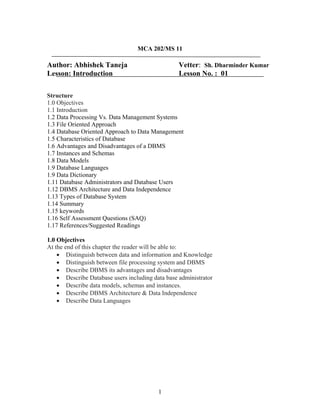
  • 20. 1.12.1 The Three-Schema Architecture The goal of the three-schema architecture, illustrated in Figure 1.1, is to separate the user applications and the physical database. In this architecture, schemas can be defined at the following three levels: 1. The internal level has an internal schema, which describes the physical storage structure of the database. The internal schema uses a physical data model and describes the complete details of data storage and access paths for the database. 2. The conceptual level has a conceptual schema, which describes the structure of the whole database for a community of users. The conceptual schema hides the details of physical storage structures and concentrates on describing entities, data types, relationships, user operations, and constraints. A high-level data model or an implementation data model can be used at this level. 3. The external or view level includes a number of external schemas or user views. Each external schema describes the part of the database that a particular user group is interested in and hides the rest of the database from that user group. A high-level data model or an implementation data model can be used at this level. Figure 1.1 The Three Schema Architecture The three-schema architecture is a convenient tool for the user to visualize the schema levels in a database system. Most DBMSs do not separate the three levels completely, but support the three-schema architecture to some extent. Some DBMSs may include physical-level details in the conceptual schema. In most DBMSs that support user views, 20
  • 21. external schemas are specified in the same data model that describes the conceptual-level information. Some DBMSs allow different data models to be used at the conceptual and external levels. Notice that the three schemas are only descriptions of data; the only data that actually exists is at the physical level. In a DBMS based on the three-schema architecture, each user group refers only to its own external schema. Hence, the DBMS must transform a request specified on an external schema into a request against the conceptual schema, and then into a request on the internal schema for processing over the stored database. If the request is a database retrieval, the data extracted from the stored database must be reformatted to match the user’s external view. The processes of transforming requests and results between levels are called mappings. These mappings may be time- consuming, so some DBMSs—especially those that are meant to support small databases—do not support external views. Even in such systems, however, a certain amount of mapping is necessary to transform requests between the conceptual and internal levels. 1.12.2 Data Independence The three-schema architecture can be used to explain the concept of data independence, which can be defined as the capacity to change the schema at one level of a database system without having to change the schema at the next higher level. We can define two types of data independence: 1. Logical data independence is the capacity to change the conceptual schema without having to change external schemas or application programs. We may change the conceptual schema to expand the database (by adding a record type or data item), or to reduce the database (by removing a record type or data item). In the latter case, external schemas that refer only to the remaining data should not be affected. Only the view definition and the mappings need be changed in a DBMS that supports logical data independence. Application programs that reference the external schema constructs must work as before, after the conceptual schema undergoes a logical reorganization. Changes to constraints can be applied also to the conceptual schema without affecting the external schemas or application programs. 21
  • 22. 2. Physical data independence is the capacity to change the internal schema without having to change the conceptual (or external) schemas. Changes to the internal schema may be needed because some physical files had to be reorganized—for example, by creating additional access structures—to improve the performance of retrieval or update. If the same data as before remains in the database, we should not have to change the conceptual schema. Whenever we have a multiple-level DBMS, its catalog must be expanded to include information on how to map requests and data among the various levels. The DBMS uses additional software to accomplish these mappings by referring to the mapping information in the catalog. Data independence is accomplished because, when the schema is changed at some level, the schema at the next higher level remains unchanged; only the mapping between the two levels is changed. Hence, application programs referring to the higher-level schema need not be changed. The three-schema architecture can make it easier to achieve true data independence, both physical and logical. However, the two levels of mappings create an overhead during compilation or execution of a query or program, leading to inefficiencies in the DBMS. Because of this, few DBMSs have implemented the full three-schema architecture. 1.13 Types of Database System Several criteria are normally used to classify DBMSs. The first is the data model on which the DBMS is based. The main data model used in many current commercial DBMSs is the relational data model. The object data model was implemented in some commercial systems but has not had widespread use. Many legacy (older) applications still run on database systems based on the hierarchical and network data models. The relational DBMSs are evolving continuously, and, in particular, have been incorporating many of the concepts that were developed in object databases. This has led to a new class of DBMSs called object-relational DBMSs. We can hence categorize DBMSs based on the data model: relational, object, object-relational, hierarchical, network, and other. The second criterion used to classify DBMSs is the number of users supported by the system. Single-user systems support only one user at a time and are mostly used with personal computers. Multiuser systems, which include the majority of DBMSs, support multiple users concurrently. A third criterion is the number of sites over which the 22
  • 23. database is distributed. A DBMS is centralized if the data is stored at a single computer site. A centralized DBMS can support multiple users, but the DBMS and the database themselves reside totally at a single computer site. A distributed DBMS (DDBMS) can have the actual database and DBMS software distributed over many sites, connected by a computer network. Homogeneous DDBMSs use the same DBMS software at multiple sites. A recent trend is to develop software to access several autonomous preexisting databases stored under heterogeneous llBMSs. This leads to a federated DBMS (or multidatabase system), in which the participating DBMSs are loosely coupled and have a degree of local autonomy. Many DBMSs use a client-server architecture. 1.14 Summary In this chapter we have discussed in a relatively informal manner the major components of a database system. We summarise the discussion below: A database-management system (DBMS) is a collection of interrelated data and a set of programs to access those data. This is a collection of related data with an implicit meaning and hence is a database. A datum – a unit of data – is a symbol or a set of symbols which is used to represent something. This relationship between symbols and what they represent is the essence of what we mean by information. Knowledge refers to the practical use of information. The collection of information stored in the database at a particular moment is called an instance of the database. The overall design of the database is called the database schema. The physical schema describes the database design at the physical level, while the logical schema describes the database design at the logical level.Adatabase may also have several schemas at the view level, sometimes called subschemas, that describe different views of the database. Application programs are said to exhibit physical data independence if they do not depend on the physical schema, and thus need not be rewritten if the physical schema changes. Underlying the structure of a database is the data model: a collection of conceptual tools for describing data, data relationships, data semantics, and consistency constraints. 23
  • 24. A database system provides a data definition language to specify the database schema and a data manipulation language to express database queries and updates. One of the main reasons for using DBMSs is to have central control of both the data and the programs that access those data. A person who has such central control over the system is called a database administrator (DBA). 1.15 Key Words DBMS, Data Integrity, Data Persistence, Instances, Schemas, Physical Schema, Logical Schema, Data Model, DDL, DML, Data Dictionary 1.16 Self Assessment Questions 1. Why would you choose a database system instead of simply storing data in operating system files? When would it make sense not to use a database system? 2. What is logical data independence and why is it important? 3. Explain the difference between logical and physical data independence. 4. Explain the difference between external, internal, and conceptual schemas. How are these different schema layers related to the concepts of logical and physical data independence? 5. What are the responsibilities of a DBA? 6. Distinguish between logical and physical database design. 7. Describe and define the key properties of a database system. Give an organizational example of the benefits of each property. 1.17 References/Suggested Readings 1 http://www.microsoft-accesssolutions.co.uk 2 Date, C, J, Introduction to Database Systems, 7 th edition 3 Leon, Alexis and Leon, Mathews, Database Management Systems, LeonTECHWorld. 24
  • 25. MCA 202/MS 11 Author: Abhishek Taneja Vetter: Sh. Dharminder Kumar Lesson No. : 02 Lesson: Data Modeling Using Entity-Relationship Approach Structure 2.0 Objectives 2.1 Introduction 2.2 Data Modeling In the Context of Database Design 2.3 The Entity-Relationship Model 2.4 Data Modeling As Part of Database Design 2.5 Steps In Building the Data Model 2.6 Developing the Basic Schema 2.7 Summary 2.8 Key Words 2.9 Self Assessment Questions 2.10 References/Suggested Readings 2.0 Objectives At the end of this chapter the reader will be able to: • Describe basic concepts of ER Model • Describe components of a data model • Describe basic constructs of E-R Modeling • Describe data modeling as a part of database design process • Describe steps in building the data model • Describe developing the basic schema 1
  • 26. 2.1 Introduction A data model is a conceptual representation of the data structures that are required by a database. The data structures include the data objects, the associations between data objects, and the rules which govern operations on the objects. As the name implies, the data model focuses on what data is required and how it should be organized rather than what operations will be performed on the data. To use a common analogy, the data model is equivalent to an architect's building plans. A data model is independent of hardware or software constraints. Rather than try to represent the data as a database would see it, the data model focuses on representing the data as the user sees it in the "real world". It serves as a bridge between the concepts that make up real-world events and processes and the physical representation of those concepts in a database. Methodology There are two major methodologies used to create a data model: the Entity-Relationship (ER) approach and the Object Model. This document uses the Entity-Relationship approach. 2.2 Data Modeling In the Context of Database Design Database design is defined as: "design the logical and physical structure of one or more databases to accommodate the information needs of the users in an organization for a defined set of applications". The design process roughly follows five steps: 1. Planning and analysis 2. Conceptual design 3. Logical design 4. Physical design 5. Implementation The data model is one part of the conceptual design process. The other, typically is the functional model. The data model focuses on what data should be stored in the database while the functional model deals with how the data is processed. To put this in the context of the relational database, the data model is used to design the relational tables. The functional model is used to design the queries which will access and perform operations on those tables. 2
  • 27. Components of a Data Model The data model gets its inputs from the planning and analysis stage. Here the modeler, along with analysts, collects information about the requirements of the database by reviewing existing documentation and interviewing end-users. The data model has two outputs. The first is an entity-relationship diagram which represents the data structures in a pictorial form. Because the diagram is easily learned, it is valuable tool to communicate the model to the end-user. The second component is a data document. This a document that describes in detail the data objects, relationships, and rules required by the database. The dictionary provides the detail required by the database developer to construct the physical database. Why is Data Modeling Important? Data modeling is probably the most labor intensive and time consuming part of the development process. Why bother especially if you are pressed for time? A common response by practitioners who write on the subject is that you should no more build a database without a model than you should build a house without blueprints. The goal of the data model is to make sure that the all data objects required by the database are completely and accurately represented. Because the data model uses easily understood notations and natural language , it can be reviewed and verified as correct by the end-users. The data model is also detailed enough to be used by the database developers to use as a "blueprint" for building the physical database. The information contained in the data model will be used to define the relational tables, primary and foreign keys, stored procedures, and triggers. A poorly designed database will require more time in the long- term. Without careful planning you may create a database that omits data required to create critical reports, produces results that are incorrect or inconsistent, and is unable to accommodate changes in the user's requirements. 2.3 The Entity-Relationship Model The Entity-Relationship (ER) model was originally proposed by Peter in 1976 as a way to unify the network and relational database views. Simply stated the ER model is a conceptual data model that views the real world as entities and relationships. A basic component of the model is the Entity-Relationship diagram which is used to visually 3
  • 28. represents data objects. Since Chen wrote his paper the model has been extended and today it is commonly used for database design For the database designer, the utility of the ER model is: It maps well to the relational model. The constructs used in the ER model can easily be transformed into relational tables. It is simple and easy to understand with a minimum of training. Therefore, the model can be used by the database designer to communicate the design to the end user. In addition, the model can be used as a design plan by the database developer to implement a data model in a specific database management software. Basic Constructs of E-R Modeling The ER model views the real world as a construct of entities and association between entities. Entities Entities are the principal data object about which information is to be collected. Entities are usually recognizable concepts, either concrete or abstract, such as person, places, things, or events which have relevance to the database. Some specific examples of entities are EMPLOYEES, PROJECTS, INVOICES. An entity is analogous to a table in the relational model. Entities are classified as independent or dependent (in some methodologies, the terms used are strong and weak, respectively). An independent entity is one that does not rely on another for identification. A dependent entity is one that relies on another for identification. An entity occurrence (also called an instance) is an individual occurrence of an entity. An occurrence is analogous to a row in the relational table. Special Entity Types Associative entities (also known as intersection entities) are entities used to associate two or more entities in order to reconcile a many-to-many relationship. Subtypes entities are used in generalization hierarchies to represent a subset of instances of their parent entity, called the supertype, but which have attributes or relationships that apply only to the subset. Associative entities and generalization hierarchies are discussed in more detail below. 4
  • 29. Relationships A Relationship represents an association between two or more entities. An example of a relationship would be: Employees are assigned to projects Projects have subtasks Departments manage one or more projects Relationships are classified in terms of degree, connectivity, cardinality, and existence. These concepts will be discussed below. Attributes Attributes describe the entity of which they are associated. A particular instance of an attribute is a value. For example, "Jane R. Hathaway" is one value of the attribute Name. The domain of an attribute is the collection of all possible values an attribute can have. The domain of Name is a character string. Attributes can be classified as identifiers or descriptors. Identifiers, more commonly called keys, uniquely identify an instance of an entity. A descriptor describes a non- unique characteristic of an entity instance. Classifying Relationships Relationships are classified by their degree, connectivity, cardinality, direction, type, and existence. Not all modeling methodologies use all these classifications. Degree of a Relationship The degree of a relationship is the number of entities associated with the relationship. The n-ary relationship is the general form for degree n. Special cases are the binary, and ternary ,where the degree is 2, and 3, respectively. Binary relationships, the association between two entities is the most common type in the real world. A recursive binary relationship occurs when an entity is related to itself. An example might be "some employees are married to other employees". A ternary relationship involves three entities and is used when a binary relationship is inadequate. Many modeling approaches recognize only binary relationships. Ternary or n-ary relationships are decomposed into two or more binary relationships. Connectivity and Cardinality The connectivity of a relationship describes the mapping of associated entity instances in the relationship. The values of connectivity are "one" or 5
  • 30. "many". The cardinality of a relationship is the actual number of related occurences for each of the two entities. The basic types of connectivity for relations are: one-to-one, one- to-many, and many-to-many. A one-to-one (1:1) relationship is when at most one instance of a entity A is associated with one instance of entity B. For example, "employees in the company are each assigned their own office. For each employee there exists a unique office and for each office there exists a unique employee. A one-to-many (1:N) relationships is when for one instance of entity A, there are zero, one, or many instances of entity B, but for one instance of entity B, there is only one instance of entity A. An example of a 1:N relationships is A department has many employees Each employee is assigned to one department A many-to-many (M:N) relationship, sometimes called non-specific, is when for one instance of entity A, there are zero, one, or many instances of entity B and for one instance of entity B there are zero, one, or many instances of entity A. An example is: employees can be assigned to no more than two projects at the same time; projects must have assigned at least three employees A single employee can be assigned to many projects; conversely, a single project can have assigned to it many employee. Here the cardinality for the relationship between employees and projects is two and the cardinality between project and employee is three. Many-to-many relationships cannot be directly translated to relational tables but instead must be transformed into two or more one-to-many relationships using associative entities. Direction The direction of a relationship indicates the originating entity of a binary relationship. The entity from which a relationship originates is the parent entity; the entity where the relationship terminates is the child entity. The direction of a relationship is determined by its connectivity. In a one-to-one relationship the direction is from the independent entity to a dependent entity. If both entities are independent, the direction is arbitrary. With one-to-many relationships, the 6
  • 31. entity occurring once is the parent. The direction of many-to-many relationships is arbitrary. Type An identifying relationship is one in which one of the child entities is also a dependent entity. A non-identifying relationship is one in which both entities are independent. Existence Existence denotes whether the existence of an entity instance is dependent upon the existence of another, related, entity instance. The existence of an entity in a relationship is defined as either mandatory or optional. If an instance of an entity must always occur for an entity to be included in a relationship, then it is mandatory. An example of mandatory existence is the statement "every project must be managed by a single department". If the instance of the entity is not required, it is optional. An example of optional existence is the statement, "employees may be assigned to work on projects". Generalization Hierarchies A generalization hierarchy is a form of abstraction that specifies that two or more entities that share common attributes can be generalized into a higher level entity type called a supertype or generic entity. The lower-level of entities become the subtype, or categories, to the supertype. Subtypes are dependent entities. Generalization occurs when two or more entities represent categories of the same real- world object. For example, Wages_Employees and Classified_Employees represent categories of the same entity, Employees. In this example, Employees would be the supertype; Wages_Employees and Classified_Employees would be the subtypes. Subtypes can be either mutually exclusive (disjoint) or overlapping (inclusive). A mutually exclusive category is when an entity instance can be in only one category. The above example is a mutually exclusive category. An employee can either be wages or classified but not both. An overlapping category is when an entity instance may be in two or more subtypes. An example would be a person who works for a university could also be a student at that same university. The completeness constraint requires that all instances of the subtype be represented in the supertype. Generalization hierarchies can be nested. That is, a subtype of one hierarchy can be a supertype of another. The level of 7
  • 32. nesting is limited only by the constraint of simplicity. Subtype entities may be the parent entity in a relationship but not the child. ER Notation There is no standard for representing data objects in ER diagrams. Each modeling methodology uses its own notation. All notational styles represent entities as rectangular boxes and relationships as lines connecting boxes. Each style uses a special set of symbols to represent the cardinality of a connection. The notation used in this document is from Martin. The symbols used for the basic ER constructs are: • Entities are represented by labeled rectangles. The label is the name of the entity. Entity names should be singular nouns. • Relationships are represented by a solid line connecting two entities. The name of the relationship is written above the line. Relationship names should be verbs. • Attributes, when included, are listed inside the entity rectangle. Attributes which are identifiers are underlined. Attribute names should be singular nouns. • Cardinality of many is represented by a line ending in a crow's foot. If the crow's foot is omitted, the cardinality is one. • Existence is represented by placing a circle or a perpendicular bar on the line. Mandatory existence is shown by the bar (looks like a 1) next to the entity for an instance is required. Optional existence is shown by placing a circle next to the entity that is optional. Examples of these symbols are shown in Figure 2.1 below: Figure 2.1 ER Notation 8
  • 33. 2.4 Data Modeling As Part of Database Design The data model is one part of the conceptual design process. The other is the function model. The data model focuses on what data should be stored in the database while the function model deals with how the data is processed. To put this in the context of the relational database, the data model is used to design the relational tables. The functional model is used to design the queries that will access and perform operations on those tables. Data modeling is preceeded by planning and analysis. The effort devoted to this stage is proportional to the scope of the database. The planning and analysis of a database intended to serve the needs of an enterprise will require more effort than one intended to serve a small workgroup. The information needed to build a data model is gathered during the requirments analysis. Although not formally considered part of the data modeling stage by some methodologies, in reality the requirements analysis and the ER diagramming part of the data model are done at the same time. Requirements Analysis The goals of the requirements analysis are: • To determine the data requirements of the database in terms of primitive objects • To classify and describe the information about these objects • To identify and classify the relationships among the objects • To determine the types of transactions that will be executed on the database and the interactions between the data and the transactions • To identify rules governing the integrity of the data The modeler, or modelers, works with the end users of an organization to determine the data requirements of the database. Information needed for the requirements analysis can be gathered in several ways: Review of existing documents - such documents include existing forms and reports, written guidelines, job descriptions, personal narratives, and memoranda. Paper documentation is a good way to become familiar with the organization or activity you need to model. 9
  • 34. Interviews with end users - these can be a combination of individual or group meetings. Try to keep group sessions to under five or six people. If possible, try to have everyone with the same function in one meeting. Use a blackboard, flip charts, or overhead transparencies to record information gathered from the interviews. Review of existing automated systems - if the organization already has an automated system, review the system design specifications and documentation The requirements analysis is usually done at the same time as the data modeling. As information is collected, data objects are identified and classified as either entities, attributes, or relationship; assigned names; and, defined using terms familiar to the end- users. The objects are then modeled and analysed using an ER diagram. The diagram can be reviewed by the modeler and the end-users to determine its completeness and accuracy. If the model is not correct, it is modified, which sometimes requires additional information to be collected. The review and edit cycle continues until the model is certified as correct. Three points to keep in mind during the requirements analysis are: 1. Talk to the end users about their data in "real-world" terms. Users do not think in terms of entities, attributes, and relationships but about the actual people, things, and activities they deal with daily. 2. Take the time to learn the basics about the organization and its activities that you want to model. Having an understanding about the processes will make it easier to build the model. 3. End-users typically think about and view data in different ways according to their function within an organization. Therefore, it is important to interview the largest number of people that time permits. 2.5 Steps In Building the Data Model While ER model lists and defines the constructs required to build a data model, there is no standard process for doing so. Some methodologies, such as IDEFIX, specify a bottom-up development process were the model is built in stages. Typically, the entities and relationships are modeled first, followed by key attributes, and then the model is finished by adding non-key attributes. Other experts argue that in practice, using a phased 10
  • 35. approach is impractical because it requires too many meetings with the end-users. The sequence used for this document are: 1. Identification of data objects and relationships 2. Drafting the initial ER diagram with entities and relationships 3. Refining the ER diagram 4. Add key attributes to the diagram 5. Adding non-key attributes 6. Diagramming Generalization Hierarchies 7. Validating the model through normalization 8. Adding business and integrity rules to the Model In practice, model building is not a strict linear process. As noted above, the requirements analysis and the draft of the initial ER diagram often occur simultaneously. Refining and validating the diagram may uncover problems or missing information which require more information gathering and analysis Identifying Data Objects and Relationships In order to begin constructing the basic model, the modeler must analyze the information gathered during the requirements analysis for the purpose of: • Classifying data objects as either entities or attributes • Identifying and defining relationships between entities • Naming and defining identified entities, attributes, and relationships • Documenting this information in the data document To accomplish these goals the modeler must analyze narratives from users, notes from meeting, policy and procedure documents, and, if lucky, design documents from the current information system. Although it is easy to define the basic constructs of the ER model, it is not an easy task to distinguish their roles in building the data model. What makes an object an entity or attribute? For example, given the statement "employees work on projects". Should employees be classified as an entity or attribute? Very often, the correct answer depends upon the requirements of the database. In some cases, employee would be an entity, in some it would be an attribute. 11
  • 36. While the definitions of the constructs in the ER Model are simple, the model does not address the fundamental issue of how to identify them. Some commonly given guidelines are: • Entities contain descriptive information • Attributes either identify or describe entities • Relationships are associations between entities These guidelines are discussed in more detail below. • Entities • Attributes o Validating Attributes o Derived Attributes and Code Values • Relationships • Naming Data Objects • Object Definition • Recording Information in Design Document Entities There are various definitions of an entity: "Any distinguishable person, place, thing, event, or concept, about which information is kept" "A thing which can be distinctly identified" "Any distinguishable object that is to be represented in a database" "...anything about which we store information (e.g. supplier, machine tool, employee, utility pole, airline seat, etc.). For each entity type, certain attributes are stored". These definitions contain common themes about entities: o An entity is a "thing", "concept" or, object". However, entities can sometimes represent the relationships between two or more objects. This type of entity is known as an associative entity. o Entities are objects which contain descriptive information. If an data object you have identified is described by other objects, then it is an entity. If there is no descriptive information associated with the item, it is not an entity. Whether or 12
  • 37. not a data object is an entity may depend upon the organization or activity being modeled. o An entity represents many things which share properties. They are not single things. For example, King Lear and Hamlet are both plays which share common attributes such as name, author, and cast of characters. The entity describing these things would be PLAY, with King Lear and Hamlet being instances of the entity. o Entities which share common properties are candidates for being converted to generalization hierarchies (See below) o Entities should not be used to distinguish between time periods. For example, the entities 1st Quarter Profits, 2nd Quarter Profits, etc. should be collapsed into a single entity called Profits. An attribute specifying the time period would be used to categorize by time o Not every thing the users want to collect information about will be an entity. A complex concept may require more than one entity to represent it. Others "things" users think important may not be entities. Attributes Attributes are data objects that either identify or describe entities. Attributes that identify entities are called key attributes. Attributes that describe an entity are called non-key attributes. Key attributes will be discussed in detail in a latter section. The process for identifying attributes is similar except now you want to look for and extract those names that appear to be descriptive noun phrases. Validating Attributes Attribute values should be atomic, that is, present a single fact. Having disaggregated data allows simpler programming, greater reusability of data, and easier implementation of changes. Normalization also depends upon the "single fact" rule being followed. Common types of violations include: o Simple aggregation - a common example is Person Name which concatenates first name, middle initial, and last name. Another is Address which concatenates, street address, city, and zip code. When dealing with such attributes, you need to find out if there are good reasons for decomposing them. For example, do the end- 13
  • 38. users want to use the person's first name in a form letter? Do they want to sort by zip code? o Complex codes - these are attributes whose values are codes composed of concatenated pieces of information. An example is the code attached to automobiles and trucks. The code represents over 10 different pieces of information about the vehicle. Unless part of an industry standard, these codes have no meaning to the end user. They are very difficult to process and update. o Text blocks - these are free-form text fields. While they have a legitimate use, an over reliance on them may indicate that some data requirements are not met by the model. o Mixed domains - this is where a value of an attribute can have different meaning under different conditions Derived Attributes and Code Values Two areas where data modeling experts disagree is whether derived attributes and attributes whose values are codes should be permitted in the data model. Derived attributes are those created by a formula or by a summary operation on other attributes. Arguments against including derived data are based on the premise that derived data should not be stored in a database and therefore should not be included in the data model. The arguments in favor are: o Derived data is often important to both managers and users and therefore should be included in the data model o It is just as important, perhaps more so, to document derived attributes just as you would other attributes o Including derived attributes in the data model does not imply how they will be implemented A coded value uses one or more letters or numbers to represent a fact. For example, the value Gender might use the letters "M" and "F" as values rather than "Male" and "Female". Those who are against this practice cite that codes have no intuitive meaning to the end-users and add complexity to processing data. Those in favor argue that many organizations have a long history of using coded attributes, that codes save space, and 14
  • 39. improve flexibility in that values can be easily added or modified by means of look-up tables. Relationships Relationships are associations between entities. Typically, a relationship is indicated by a verb connecting two or more entities. For example: employees are assigned to projects As relationships are identified they should be classified in terms of cardinality, optionality, direction, and dependence. As a result of defining the relationships, some relationships may be dropped and new relationships added. Cardinality quantifies the relationships between entities by measuring how many instances of one entity are related to a single instance of another. To determine the cardinality, assume the existence of an instance of one of the entities. Then determine how many specific instances of the second entity could be related to the first. Repeat this analysis reversing the entities. For example: Employees may be assigned to no more than three projects at a time; every project has at least two employees assigned to it. Here the cardinality of the relationship from employees to projects is three; from projects to employees, the cardinality is two. Therefore, this relationship can be classified as a many-to-many relationship. If a relationship can have a cardinality of zero, it is an optional relationship. If it must have a cardinality of at least one, the relationship is mandatory. Optional relationships are typically indicated by the conditional tense. For example: An employee may be assigned to a project Mandatory relationships, on the other hand, are indicated by words such as must have. For example: A student must register for at least three course each semester In the case of the specific relationship form (1:1 and 1:M), there is always a parent entity and a child entity. In one-to-many relationships, the parent is always the entity with the cardinality of one. In one-to-one relationships, the choice of the parent entity must be made in the context of the business being modeled. If a decision cannot be made, the choice is arbitrary. 15
  • 40. Naming Data Objects The names should have the following properties: o Unique o Have meaning to the end-user o Contain the minimum number of words needed to uniquely and accurately describe the object For entities and attributes, names are singular nouns while relationship names are typically verbs. Some authors advise against using abbreviations or acronyms because they might lead to confusion about what they mean. Other believe using abbreviations or acronyms are acceptable provided that they are universally used and understood within the organization. You should also take care to identify and resolve synonyms for entities and attributes. This can happen in large projects where different departments use different terms for the same thing. Object Definition Complete and accurate definitions are important to make sure that all parties involved in the modeling of the data know exactly what concepts the objects are representing. Definitions should use terms familiar to the user and should precisely explain what the object represents and the role it plays in the enterprise. Some authors recommend having the end-users provide the definitions. If acronyms, or terms not universally understood are used in the definition, then these should be defined . While defining objects, the modeler should be careful to resolve any instances where a single entity is actually representing two different concepts (homonyms) or where two different entities are actually representing the same "thing" (synonyms). This situation typically arises because individuals or organizations may think about an event or process in terms of their own function. An example of a homonym would be a case where the Marketing Department defines the entity MARKET in terms of geographical regions while the Sales Departments thinks of this entity in terms of demographics. Unless resolved, the result would be an entity with two different meanings and properties. 16
  • 41. Conversely, an example of a synonym would be the Service Department may have identified an entity called CUSTOMER while the Help Desk has identified the entity CONTACT. In reality, they may mean the same thing, a person who contacts or calls the organization for assistance with a problem. The resolution of synonyms is important in order to avoid redundancy and to avoid possible consistency or integrity problems. Recording Information in Design Document The design document records detailed information about each object used in the model. As you name, define, and describe objects, this information should be placed in this document. If you are not using an automated design tool, the document can be done on paper or with a word processor. There is no standard for the organization of this document but the document should include information about names, definitions, and, for attributes, domains. Two documents used in the IDEF1X method of modeling are useful for keeping track of objects. These are the ENTITY-ENTITY matrix and the ENTITY-ATTRIBUTE matrix. The ENTITY-ENTITY matrix is a two-dimensional array for indicating relationships between entities. The names of all identified entities are listed along both axes. As relationships are first identified, an "X" is placed in the intersecting points where any of the two axes meet to indicate a possible relationship between the entities involved. As the relationship is further classified, the "X" is replaced with the notation indicating cardinality. The ENTITY-ATTRIBUTE matrix is used to indicate the assignment of attributes to entities. It is similar in form to the ENTITY-ENTITY matrix except attribute names are listed on the rows. Figure 2.2 shows examples of an ENTITY-ENTITY matrix and an ENTITY- ATTRIBUTE matrix. 17
  • 42. Figure 2.2 2.6 Developing the Basic Schema Once entities and relationships have been identified and defined, the first draft of the entity relationship diagram can be created. This section introduces the ER diagram by demonstrating how to diagram binary relationships. Recursive relationships are also shown. Binary Relationships Figure 2.3 shows examples of how to diagram one-to-one, one-to-many, and many-to- many relationships. 18
  • 43. Figure 2.3 Example of Binary relationships One-To-One Figure 1A shows an example of a one-to-one diagram. Reading the diagram from left to right represents the relationship every employee is assigned a workstation. Because every employee must have a workstation, the symbol for mandatory existence—in this case the crossbar—is placed next to the WORKSTATION entity. Reading from right to left, the diagram shows that not all workstation are assigned to employees. This condition may reflect that some workstations are kept for spares or for loans. Therefore, we use the symbol for optional existence, the circle, next to EMPLOYEE. The cardinality and existence of a relationship must be derived from the "business rules" of the organization. For example, if all workstations owned by an organization were assigned to employees, then the circle would be replaced by a crossbar to indicate mandatory existence. One-to- one relationships are rarely seen in "real-world" data models. Some practioners advise 19
  • 44. that most one-to-one relationships should be collapsed into a single entity or converted to a generalization hierarchy. One-To-Many Figure 1B shows an example of a one-to-many relationship between DEPARTMENT and PROJECT. In this diagram, DEPARTMENT is considered the parent entity while PROJECT is the child. Reading from left to right, the diagram represents departments may be responsible for many projects. The optionality of the relationship reflects the "business rule" that not all departments in the organization will be responsible for managing projects. Reading from right to left, the diagram tells us that every project must be the responsibility of exactly one department. Many-To-Many Figure 1C shows a many-to-many relationship between EMPLOYEE and PROJECT. An employee may be assigned to many projects; each project must have many employee Note that the association between EMPLOYEE and PROJECT is optional because, at a given time, an employee may not be assigned to a project. However, the relationship between PROJECT and EMPLOYEE is mandatory because a project must have at least two employees assigned. Many-To-Many relationships can be used in the initial drafting of the model but eventually must be transformed into two one-to-many relationships. The transformation is required because many-to-many relationships cannot be represented by the relational model. The process for resolving many-to-many relationships is discussed in the next section. Recursive relationships A recursive relationship is an entity is associated with itself. Figure 2.4 shows an example of the recursive relationship. 20
  • 45. An employee may manage many employees and each employee is managed by one employee. Figure 2.4 Example of Recursive relationship 2.7 Summary • A data model is a plan for building a database. To be effective, it must be simple enough to communicate to the end user the data structure required by the database yet detailed enough for the database design to use to create the physical structure. • The Entity-Relation Model (ER) is the most common method used to build data models for relational databases. • The Entity-Relationship Model is a conceptual data model that views the real world as consisting of entities and relationships. The model visually represents these concepts by the Entity-Relationship diagram. • The basic constructs of the ER model are entities, relationships, and attributes. • Data modeling must be preceded by planning and analysis. • Planning defines the goals of the database, explains why the goals are important, and sets out the path by which the goals will be reached. • Analysis involves determining the requirements of the database. This is typically done by examining existing documentation and interviewing users. • Data modeling is a bottom up process. A basic model, representing entities and relationships, is developed first. Then detail is added to the model by including information about attributes and business rules. 21
  • 46. • The first step in creating the data model is to analyze the information gathered during the requirements analysis with the goal of identifying and classifying data objects and relationships • The Entity-Relationship diagram provides a pictorial representation of the major data objects, the entities, and the relationships between them. 2.8 Key Words ER Model, Database Design, Data Model, Schema, Entities, Relationship, Attributes, Cardinality 2.9 Self Assessment Questions 1. A university registrar’s office maintains data about the following entities: • Courses, including number, title, credits, syllabus, and prerequisites; • Course offerings, including course number, year, semester, section number, instructor(s), timings, and classroom; • Students, including student-id, name, and program; • Instructors, including identification number, name, department, and title. Further, the enrollment of students in courses and grades awarded to students in each course they are enrolled for must be appropriately modeled.Construct a E-R diagram for registrar’s office. Document all assumptions that you make about the mapping constraints 2. Design an E-R diagram for keeping track of the exploits of your favorite sports team. You should store the matches played, the scores in each match, the players in each match, and individual player statistics for each match. Summary statistics should be modeled as derived attributes. 3. Explain the significance of ER Model for Database design? 4. Enumerate the basic constructs of ER Model 2.10 References/Suggested Readings 1. Date, C.J., Introduction to Database Systems (7 th Edition) Addison Wesley, 2000 2. Leon, Alexis and Leon, Mathews, Database Management Systems, LeonTECHWorld 3. Elamasri R . and Navathe, S., Fundamentals of Database Systems (3 rd Edition), Pearsson Education, 2000. 22
  • 47. MCA 202/MS 11 Author: Abhishek Taneja Vetter: Dr.Pradeep Bhatia Lesson: Relational Model Lesson No. : 03 Structure 3.0 Objectives 3.1 Introduction 3.2 Relational Model Concepts 3.3 Relational Model Constraints 3.4 Relational Languages 3.5 Relational Algebra 3.6 A Relational Database Management Systems-ORACLE 3.7 Summary 3.8 Key Words 3.9 Self Assessment Questions 3.10 References/Suggested Readings 3.0 Objectives At the end of this chapter the reader will be able to: • Describe Relational Model Concepts • Describe properties of a relation and relational keys • Describe relational model/integrity constraints • Describe The Relational Algebra • Introduce Oracle- A relational database management system 1
  • 48. 3.1 Introduction The principles of the relational model were first outlined by Dr. E. F. Codd in a June 1970 paper called "A Relational Model of Data for Large Shared Data Banks:' In this paper. Dr. Codd proposed the relational model for database systems. The more popular models used at that time were hierarchical and network, or even simple flat file data structures. Relational database management systems (RDBMS) soon became very popular, especially for their ease of use and flexibility in structure. In addition, a number of innovative vendors, such as Oracle, supplemented the RDBMS with a suite of powerful application development and user products, providing a total solution. Earlier we saw how to convert an unorganized text description of information requirements into a conceptual design, by the use of ER diagrams. The advantage of ER diagrams is that they force you to identify data requirements that are implicitly known, but not explicitly written down in the original description. Here we will see how to convert this ER into a logical design (this will be defined below) of a relational database. The logical model is also called a Relational Model. 3.2 Relational Model Concepts We shall represent a relation as a table with columns and rows. Each column of the table has a name, or attribute. Each row is called a tuple. • Domain: a set of atomic values that an attribute can take • Attribute: name of a column in a particular table (all data is stored in tables). Each attribute Ai must have a domain, dom(Ai). • Relational Schema: The design of one table, containing the name of the table (i.e. the name of the relation), and the names of all the columns, or attributes. Example: STUDENT( Name, SID, Age, GPA) • Degree of a Relation: the number of attributes in the relation's schema. • Tuple, t, of R( A1, A2, A3, …, An): an ORDERED set of values, < v1, v2, v3, …, vn>, where each vi is a value from dom( Ai). 2
  • 49. • Relation Instance, r( R): a set of tuples; thus, r( R) = { t1, t2, t3, …, tm} NOTES: 1. The tuples in an instance of a relation are not considered to be ordered putting the rows in a different sequence does not change the table. 2. Once the schema, R( A1, A2, A3, …, An) is defined, the values, vi, in each tuple, t, must be ordered as t = <v1, v2, v3, …, vn> 3.2.1 Properties of relations Properties of database relations are: • relation name is distinct from all other relations • each cell of relation contains exactly one atomic (single) value • each attribute has a distinct name • values of an attribute are all from the same domain • order of attributes has no significance • each tuple is distinct; there are no duplicate tuples • order of tuples has no significance, theoretically. 3.2.2 Relational keys There are two kinds of keys in relations. The first are identifying keys: the primary key is the main concept, while two other keys – super key and candidate key – are related concepts. The second kind is the foreign key. 3
  • 50. Identity Keys Super Keys A super key is a set of attributes whose values can be used to uniquely identify a tuple within a relation. A relation may have more than one super key, but it always has at least one: the set of all attributes that make up the relation. Candidate Keys A candidate key is a super key that is minimal; that is, there is no proper subset that is itself a superkey. A relation may have more than one candidate key, and the different candidate keys may have a different number of attributes. In other words, you should not interpret 'minimal' to mean the super key with the fewest attributes. A candidate key has two properties: (i) in each tuple of R, the values of K uniquely identify that tuple (uniqueness) (ii) no proper subset of K has the uniqueness property (irreducibility). Primary Key The primary key of a relation is a candidate key especially selected to be the key for the relation. In other words, it is a choice, and there can be only one candidate key designated to be the primary key. Relationship between identity keys The relationship between keys: Superkey ⊇ Candidate Key ⊇ Primary Key Foreign keys The attribute(s) within one relation that matches a candidate key of another relation. A relation may have several foreign keys, associated with different target relations. Foreign keys allow users to link information in one relation to information in another relation. Without FKs, a database would be a collection of unrelated tables. 3.3 Relational Model Constraints Integrity Constraints Each relational schema must satisfy the following four types of constraints. A. Domain constraints Each attribute Ai must be an atomic value from dom( Ai) for that attribute. 4
  • 51. The attribute, Name in the example is a BAD DESIGN (because sometimes we may want to search a person by only using their last name. B. Key Constraints Superkey of R: A set of attributes, SK, of R such that no two tuples in any valid relational instance, r( R), will have the same value for SK. Therefore, for any two distinct tuples, t1 and t2 in r( R), t1[ SK] != t2[SK]. Key of R: A minimal superkey. That is, a superkey, K, of R such that the removal of ANY attribute from K will result in a set of attributes that are not a superkey. Example CAR( State, LicensePlateNo, VehicleID, Model, Year, Manufacturer) This schema has two keys: K1 = { State, LicensePlateNo} K2 = { VehicleID } Both K1 and K2 are superkeys. K3 = { VehicleID, Manufacturer} is a superkey, but not a key (Why?). If a relation has more than one keys, we can select any one (arbitrarily) to be the primary key. Primary Key attributes are underlined in the schema: CAR(State, LicensePlateNo, VehicleID, Model, Year, Manufacturer) C. Entity Integrity Constraints The primary key attribute, PK, of any relational schema R in a database cannot have null values in any tuple. In other words, for each table in a DB, there must be a key; for each key, every row in the table must have non-null values. This is because PK is used to identify the individual tuples. Mathematically, t[PK] != NULL for any tuple t € r( R). D. Referential Integrity Constraints Referential integrity constraints are used to specify the relationships between two relations in a database. Consider a referencing relation, R1, and a referenced relation, R2. Tuples in the referencing relation, R1, have attributed FK (called foreign key attributes) that reference 5
  • 52. the primary key attributes of the referenced relation, R2. A tuple, t1, in R1 is said to reference a tuple, t2, in R2 if t1[FK] = t2[PK]. A referential integrity constraint can be displayed in a relational database schema as a directed arc from the referencing (foreign) key to the referenced (primary) key. Examples are shown in the figure below: ER-to-Relational Mapping Now we are ready to lay down some informal methods to help us create the Relational schemas from our ER models. These will be described in the following steps: 1. For each regular entity, E, in the ER model, create a relation R that includes all the simple attributes of E. Select the primary key for E, and mark it. 2. For each weak entity type, W, in the ER model, with the Owner entity type, E, create a relation R with all attributes of W as attributes of W, plus the primary key of E. [Note: if there are identical tuples in W which share the same owner tuple, then we need to create an additional index attribute in W.] 3. For each binary relation type, R, in the ER model, identify the participating entity types, S and T. • For 1:1 relationship between S and T Choose one relation, say S. Include the primary key of T as a foreign key of S. • For 1:N relationship between S and T Let S be the entity on the N side of the relationship. Include the primary key of T as a foreign key in S. • For M: N relation between S and T 6