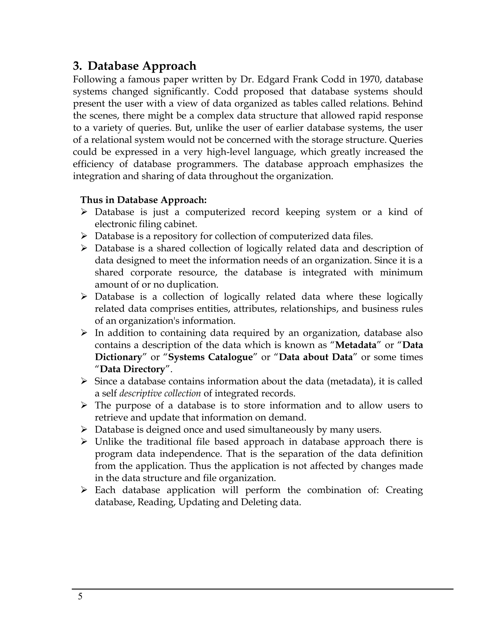
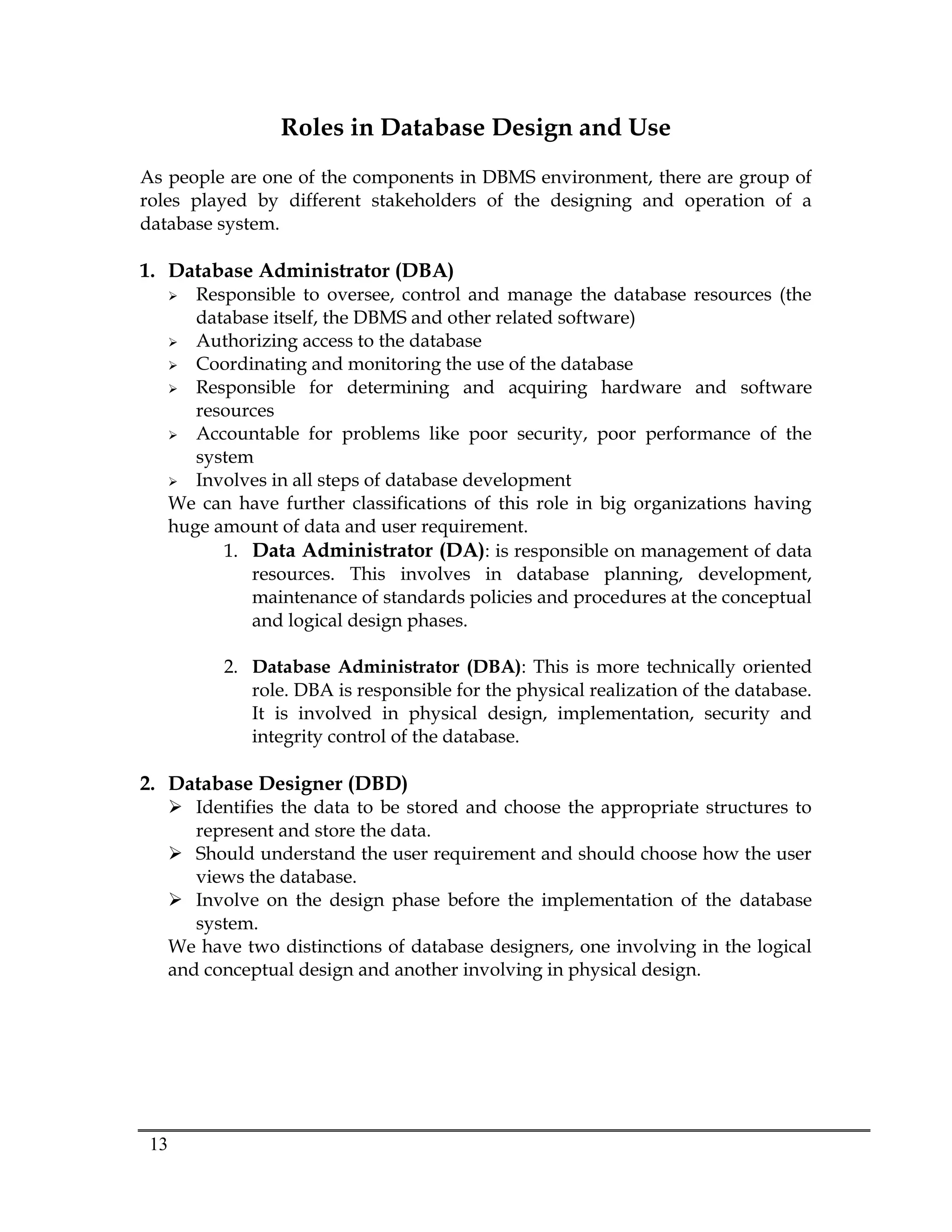
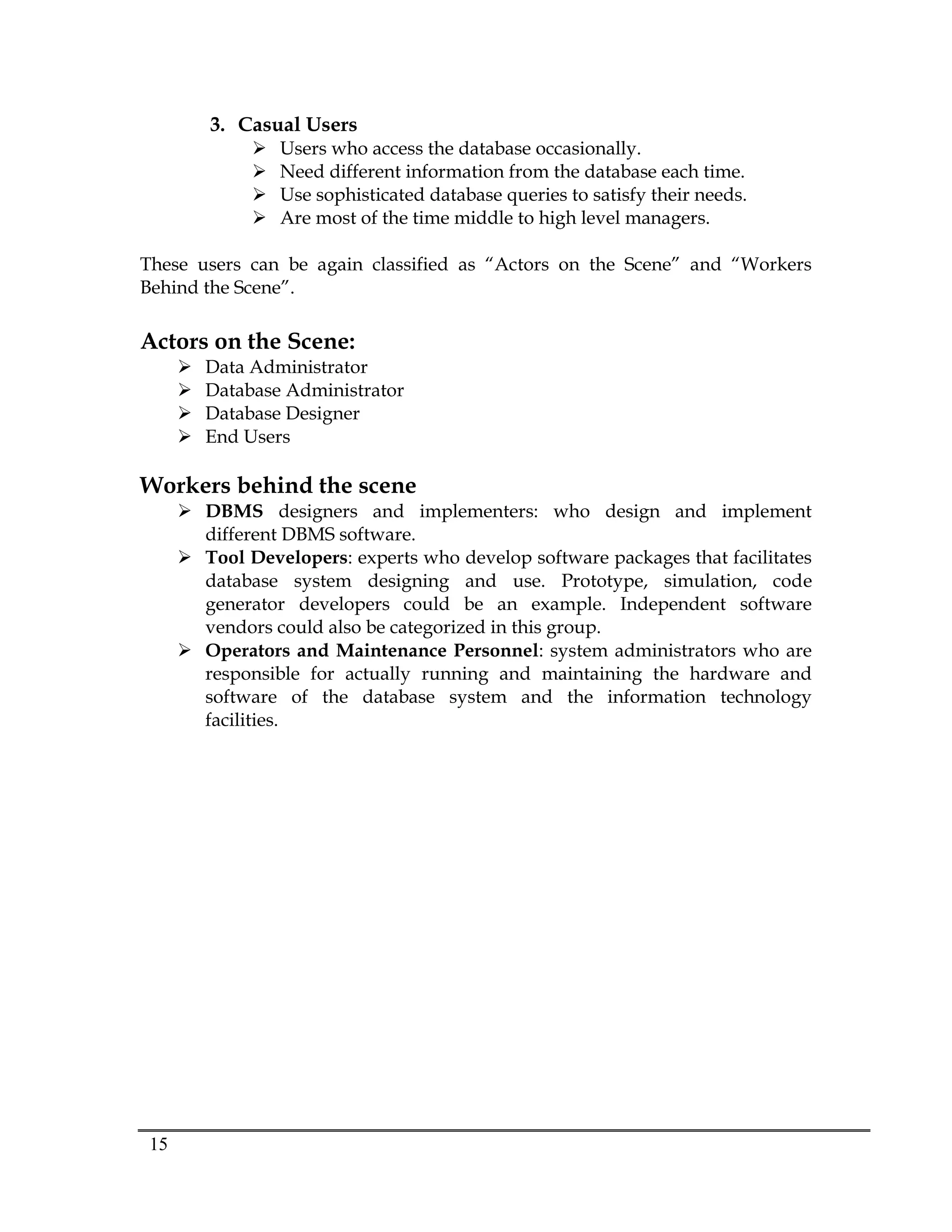
Database systems are designed to manage large datasets in an organization. A database is a collection of shared information that exists over a long period of time, often many years. A database management system (DBMS) is software that allows for the efficient creation, management, and use of large amounts of persistent and shared data. The database approach emphasizes integration and sharing of data throughout an organization, with minimum duplication and program data independence. This provides benefits like improved data accessibility, reduced redundancy, and maintained data quality and integrity.


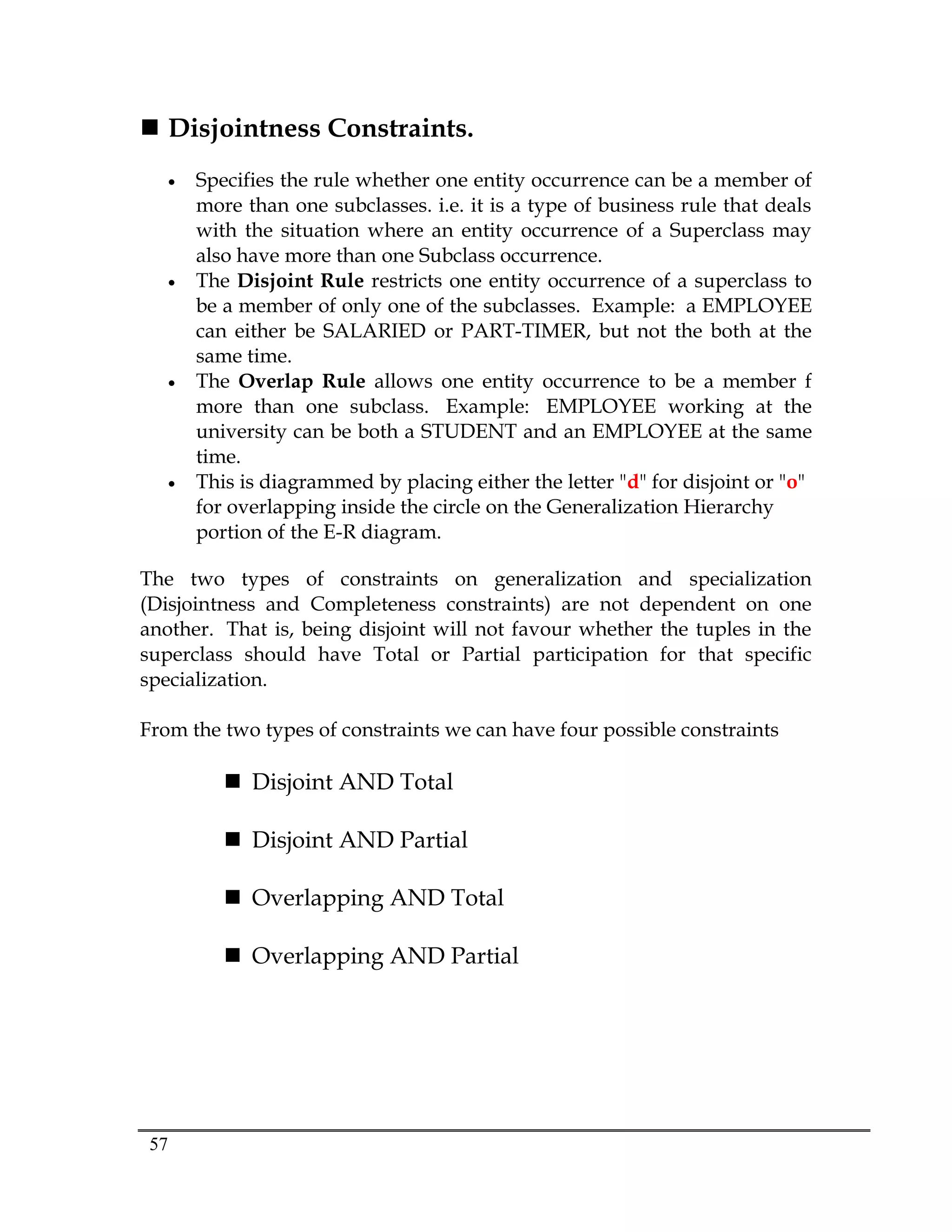
![27
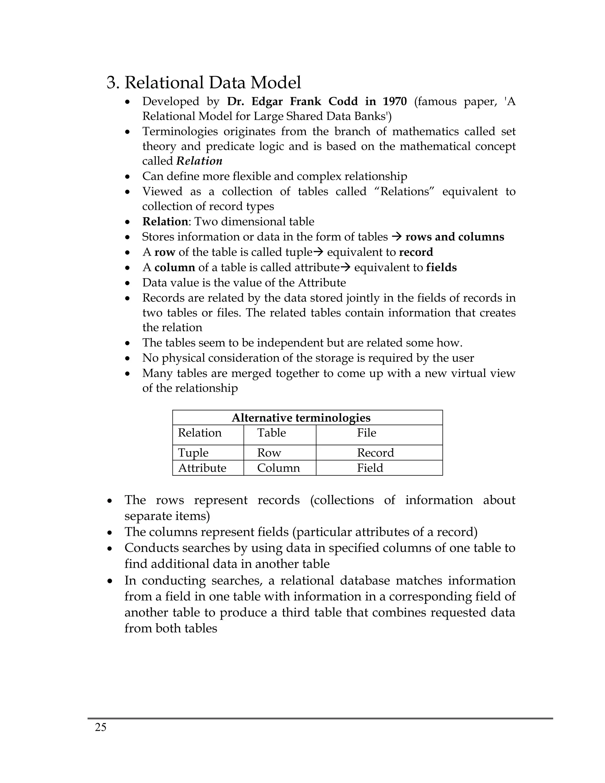
Properties of Relational Databases
A relation has a name that is distinct from all other relation names in
the relational schema.
Each tuple in a relation must be unique
All tables are LOGICAL ENTITIES
Each cell of a relation contains exactly one atomic (single) value.
Each column (field or attribute) has a distinct name.
The values of an attribute are all from the same domain.
A table is either a BASE TABLES (Named Relations) or VIEWS
(Unnamed Relations)
Only Base Tables are physically stored
VIEWS are derived from BASE TABLES with SQL statements like:
[SELECT .. FROM .. WHERE .. ORDER BY]
Relational database is the collection of tables
o Each entity in one table
o Attributes are fields (columns) in table
Order of rows theoretically ( but practically has impact on
performance) and columns is immaterial
Entries with repeating groups are said to be un-normalized
All values in a column represent the same attribute and have the same
data format](https://image.slidesharecdn.com/458844323259990698132-211001160048/75/database-ppt-2-27-2048.jpg)


![[DSC Europe 25] Ivan Peric - Intelligence Swarm Logic and Techno-Functional M...](https://cdn.slidesharecdn.com/ss_thumbnails/7my7c97fsduiccadgavw-2-251212103249-5a03f7c6-thumbnail.jpg?width=640&height=640&fit=bounds)


![[DSC Europe 25] Kaja Kandare - LLM as a judge.pptx](https://cdn.slidesharecdn.com/ss_thumbnails/arxyccaxsdsd1ba99wjw-7-251212104007-2b4e3f64-thumbnail.jpg?width=640&height=640&fit=bounds)
![[DSC Europe 25] Dunja Adzic Jovanovic - AI and Cybersecurity: Defending Data ...](https://cdn.slidesharecdn.com/ss_thumbnails/o1zylpbhrtwnixxq2xj8-7-251211083048-185086f6-thumbnail.jpg?width=640&height=640&fit=bounds)
![[DSC Europe 25] Jon Dajci - Bridging TradFi and DeFi: Building the Future of ...](https://cdn.slidesharecdn.com/ss_thumbnails/fqmhfvlbqhkihjvqvhmu-7-251211083849-6af7e325-thumbnail.jpg?width=640&height=640&fit=bounds)
![[DSC Europe 25] Dusan Nesic - Securing Tomorrow’s Infrastructure: Why Cyber-P...](https://cdn.slidesharecdn.com/ss_thumbnails/qikbszfftyowjm2q6duw-1-251211083848-8f2ead6b-thumbnail.jpg?width=640&height=640&fit=bounds)


![[DSC Europe 25] Bassam Maharmeh - Artificial Intelligence: Opportunities and ...](https://cdn.slidesharecdn.com/ss_thumbnails/thhfmr2fqpawzj7hsjpg-5-251211083048-2c23204f-thumbnail.jpg?width=640&height=640&fit=bounds)

![[DSC Europe 25] Danica Soc - The Science Behind Marketing: Experimentation me...](https://cdn.slidesharecdn.com/ss_thumbnails/c0nofsggs9gw5ucmallr-3-251216103155-56bd64d1-thumbnail.jpg?width=640&height=640&fit=bounds)


![[DSC Europe 25] Branko Dzakula - From Defense to Attack: How AI Redefines Cyb...](https://cdn.slidesharecdn.com/ss_thumbnails/80bdzdxpr3ky2g0qvyk9-8-251211083048-ce5fc1ee-thumbnail.jpg?width=640&height=640&fit=bounds)


![[DSC Europe 25] Katherine Forrest - AI NOW: Understanding the Velocity of Cha...](https://cdn.slidesharecdn.com/ss_thumbnails/wvvbruqfrci0sfq9xwgb-4-251212104007-e5ad1987-thumbnail.jpg?width=640&height=640&fit=bounds)
