Download as PDF, PPTX
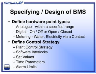
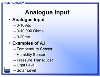
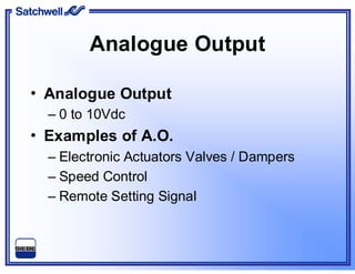
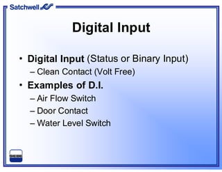
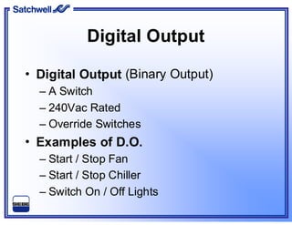
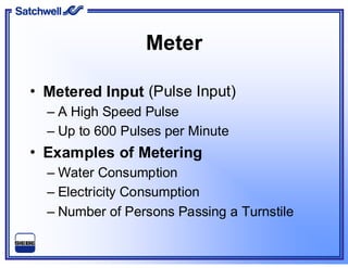
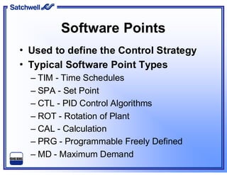
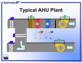
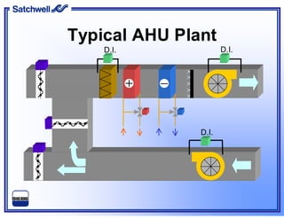


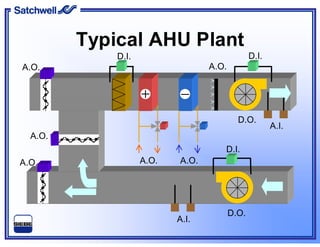
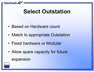

This document provides an overview of building automation systems (BAS) and their components. It describes the main point types in a BAS including analog, digital, and metering. It also outlines common input and output examples. The document discusses the software used to define the control strategy. Additionally, it shows a typical air handling unit plant layout and components. Finally, it reviews outstation and module options for collecting data from the field level.


