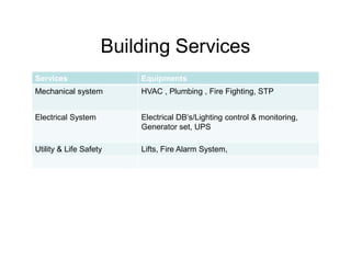
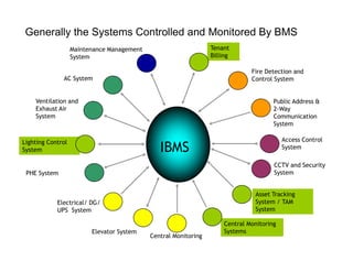
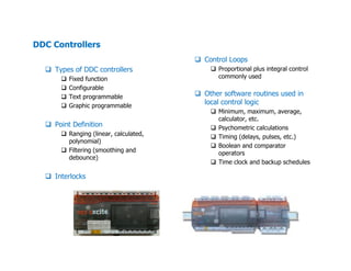
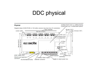
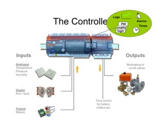
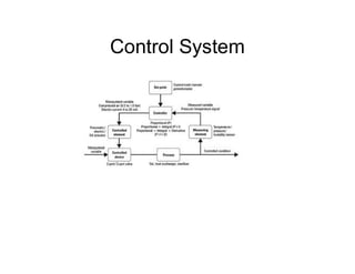
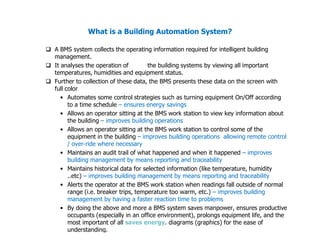
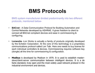
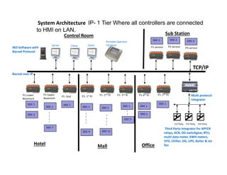
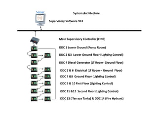
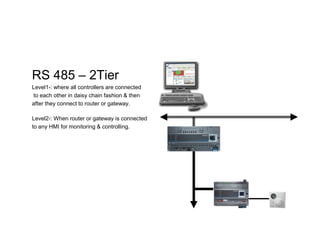
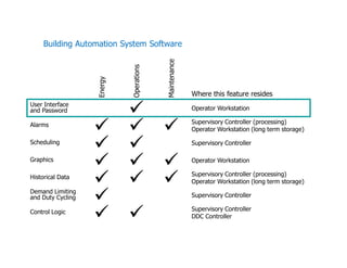
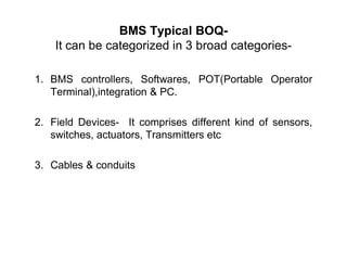
A Building Management System (BMS) is a blend of hardware and software that is used to control and monitor a building's mechanical, electrical, and other systems. It collects operating information to analyze building systems and present the data visually. A BMS can automate control strategies, allow remote monitoring and control of equipment, maintain operational records, and alert operators to conditions outside normal ranges. BMS protocols include BACnet and Lonworks. System architecture may involve different tiers with controllers connected to an HMI or to each other in a daisy chain configuration. BMS software handles functions like alarms, energy management, maintenance records, control logic, and historical data storage. A typical BMS includes controllers, field devices, integration