Download as PDF, PPTX


![MIPI Byte Packet Signaling
8’hB8
8’hB8
4-lane example
byte_data[7:0] {VC,DT} Byte(0) Byte(4) CS ECC Byte(n) …
… byte_clk
sync
byte_data[15:8] WC Byte(1) Byte(5) {VC,DT} Byte(0) Byte(n-1)
…
8’hB8 WC Byte(2) Byte(6) WC Byte(1) CS …
8’hB8 ECC Byte(3) CS WC Byte(2) CS …
byte_data[23:16]
byte_data[31:24]
8’b00011101 HS-SYNC Sequence
Packet Header
VC – Virtual Channel number
DT – Data Type
WC = 16 bit word length count
ECC – Checksum
on word count
CS –Checksum on
data](https://image.slidesharecdn.com/multicsi-2cameraaggregationinfpgas-160926030814/75/MIPI-DevCon-2016-Multiple-MIPI-CSI-2-Cameras-Leveraging-FPGAs-8-2048.jpg)


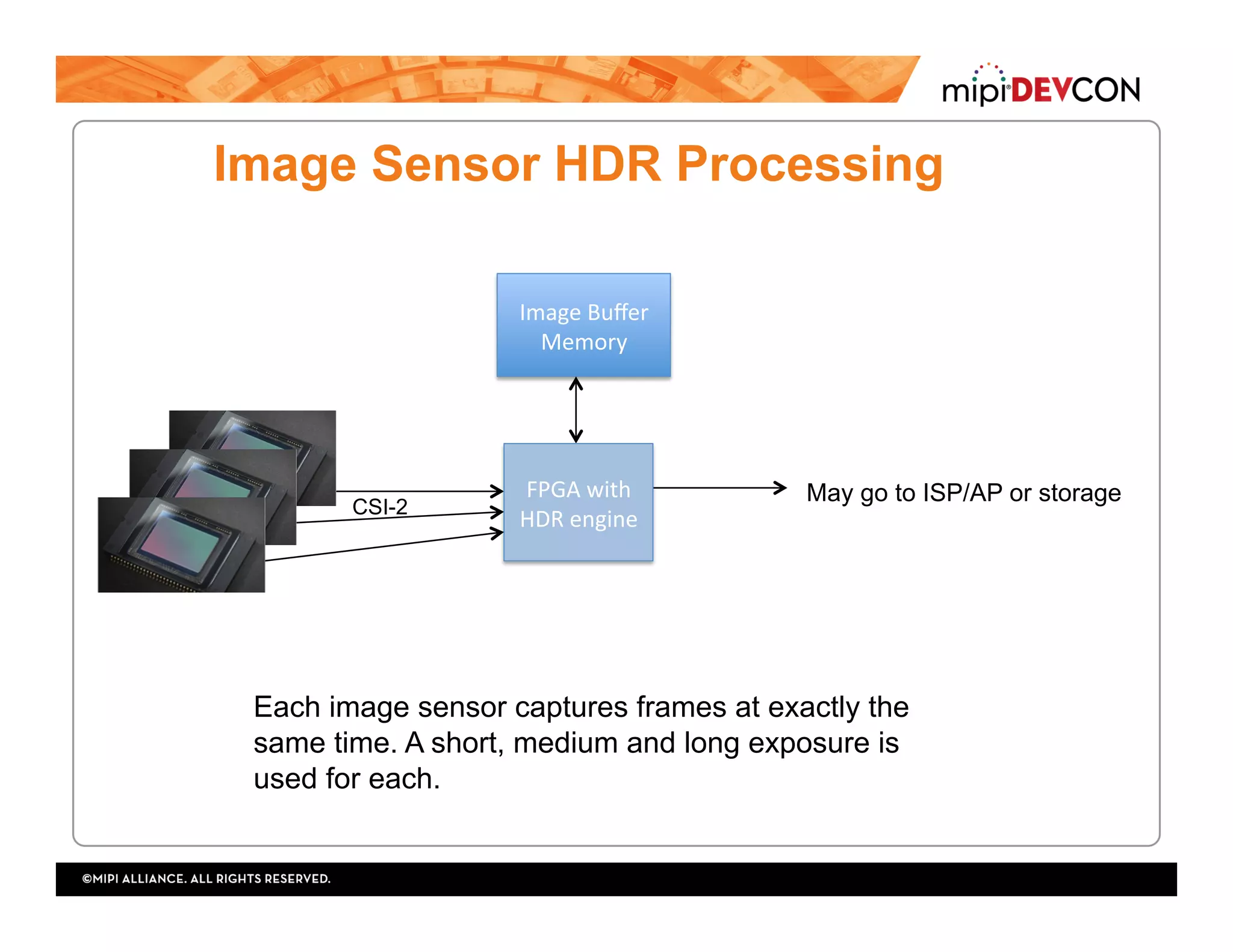


The document discusses the evolution and adoption of MIPI CSI-2 image sensors, highlighting their growing use in various applications, including 3D cameras and automotive systems. It explains the role of FPGAs in handling multiple MIPI CSI-2 connections, emphasizing their capability to perform processing and aggregation for improved performance. Additionally, the document predicts that the adoption of MIPI CSI-2 will continue to expand beyond mobile applications, leveraging the parallel architecture of FPGAs for enhanced multi-camera functionalities.