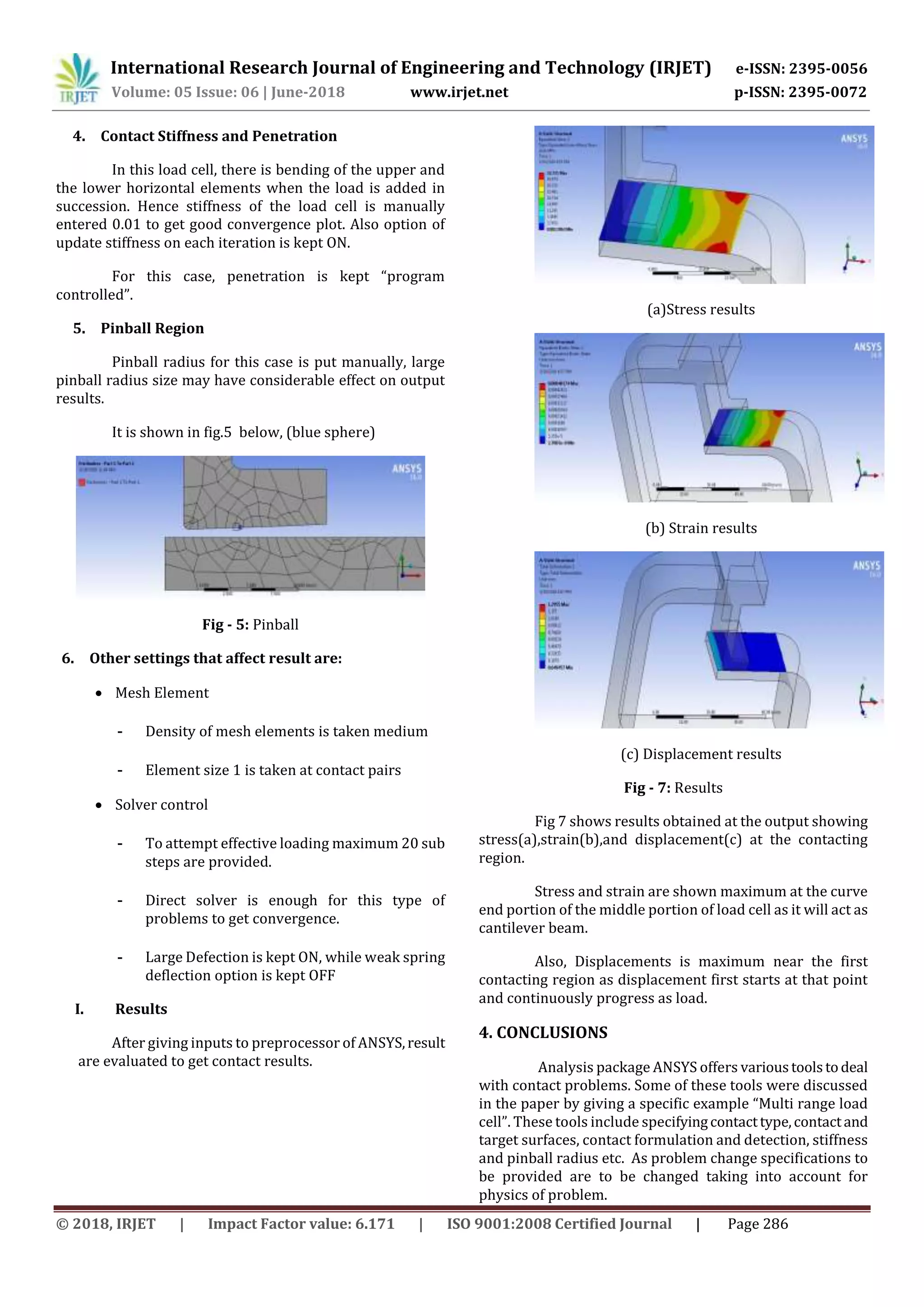
The document presents a finite element analysis for stress and non-linear contact analysis of a multi-range load cell using ANSYS software. It discusses key challenges in contact problems, such as predicting contact regions and friction, and outlines steps necessary for conducting accurate non-linear contact analysis. Various settings, including contact method and mesh density, are detailed to ensure effective solution convergence and accurate results.
![International Research Journal of Engineering and Technology (IRJET) e-ISSN: 2395-0056
Volume: 05 Issue: 06 | June-2018 www.irjet.net p-ISSN: 2395-0072
© 2018, IRJET | Impact Factor value: 6.171 | ISO 9001:2008 Certified Journal | Page 283
Finite Element analysis for stress analysis and Non-linear contact
analysis of Multi range load cell in ANSYS software
Shreyas Pandit1, Prof. Vijay Kamble2
1 PG student, Department of Mechanical Engineering, Textile and Engineering Institute, Ichalkaranji, India.
2 Professor, Department of Mechanical Engineering, Textile and Engineering Institute, Ichalkaranji, India.
---------------------------------------------------------------------***---------------------------------------------------------------------
Abstract - Contact problems are more often nonlinear and
require significant computer resourcestosolve. It isimportant
that you know about the physics of the problem and take the
time to set up your model to run as efficiently as possible.
Contact problems present two significant difficulties. First, we
generally do not know the regions where contact starts until
problem is simulated. Depending on the loads, material,
boundary conditions, and otherfactors, surfacescancomeinto
and go out of contact with each other can’tbepredictedeasily.
Second, most contact problems undergoes friction. There are
many of friction laws and problems to choose from which
mainly are nonlinear. Frictionalresponseofsuchproblemscan
be confusing, making solution convergence difficult. This
paper provides information on non-linear contact analysis
with an illustration of “Multi-range load cell” in ANSYS
software various tools required for analysis are also given but
many times differs according to problem physics.
Key Words: Non-linearcontactanalysis,loadcell,FEA,Ansys.
1. INTRODUCTION
Most of the contact problems in practice areofNon-
linear in nature. There is a need to analyze that problem in
analysis software packages with giving certain essential
commands and inputs to specific problems according to its
nature and geometry. Some of the basic cases include two
parallel cylinders, two spheres, cylinders on a flat plate,gear
teeth, roller bearings, etc. Theories and formulas for these
cases are discussed in standard design books. [1, 2]. Factors
that are to be taken into considerations are optimal mesh
size, boundary conditions, loading, connections commands
This paper illustrates Multi range load cell which
has small gap between contacting elements. Curved surface
contact with horizontal flat surface in non-linear manner as
the load goes on increasing.
While carrying FEA, care must be taken for giving
inputs in connection table.
Multi-stage load cell is another modification over
standard load cells based of strain gauge.
In the first range for light loading, there was no contact
between the two special components of the load cell. In the
second range for heavy loading, contact between the two
components occurred.
Difference contact elements are as follow:
Point-to-point gap elements
Point-to-line (or slide-line) contact elements
Point-to-surface contact elements
Surface-to-surface contact elements [3]
For this case Surface-to-surface contact elements
are chosen and steps on contact analysis are discussed
below in next section.
Fig - 1: Multi range Load cell
Fig 2:- Steps in FEA](https://image.slidesharecdn.com/irjet-v5i660-180708125355/75/Non-linear-Contact-analysis-in-Ansys-analysis-software-1-2048.jpg)
![International Research Journal of Engineering and Technology (IRJET) e-ISSN: 2395-0056
Volume: 05 Issue: 06 | June-2018 www.irjet.net p-ISSN: 2395-0072
© 2018, IRJET | Impact Factor value: 6.171 | ISO 9001:2008 Certified Journal | Page 284
Fig 2 shows steps steps involved in general finite
element analysis, while the step indicated by red colour
shows the topic of current interest i.e, contact analysis.
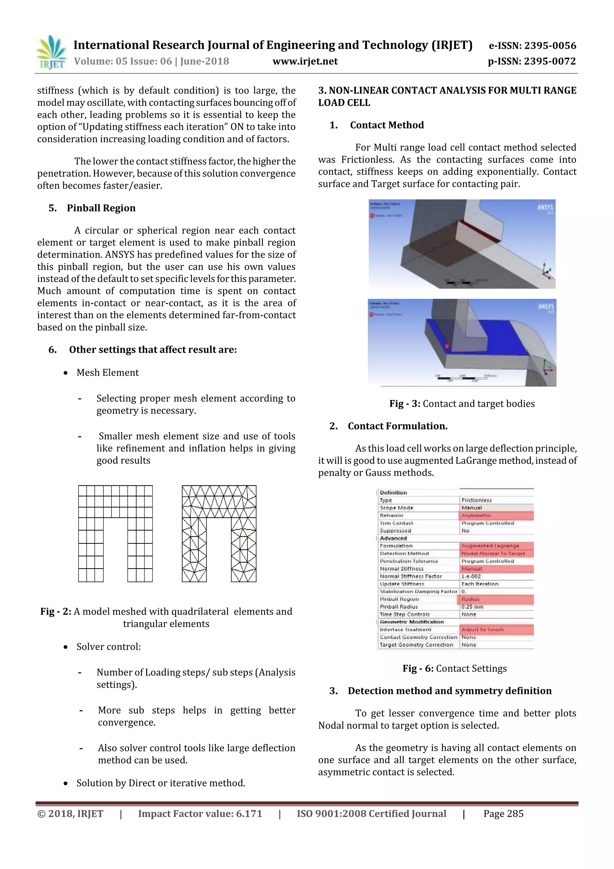
2. NON-LINEAR CONTACT ANALYSIS SETTINGS
There are number of settings that are required to be
carried out so that after analysis solution converges as
expected. Some of the contact settings are described in brief
below.
The ANSYS FEA software supports three types of
contactmodels:point-to-point,point-to-surface,andsurface-
to-surface.
Steps in a Contact Analysis
The basic steps for performing a typical surface-to-
surface contact analysis are listed below. Each step is then
explained in detail in the following pages.
1. Create the model geometry and mesh.
2. Identify the contact pairs.
3. Choose contact and target surfaces.
4. Define the target surface.
5. Define the contact surface.
6. Set the element key options and real constants.
7. Define/control the motion of the target surface
(rigid-to-flexible only).
8. Apply necessary boundary conditions.
9. Define solution options and load steps.
10. Solve the contact problem.
11. Review the results.
These steps are discussed below with brief of every
stage in process,
1. First step is to mention contact method which may
be:
Bonded type contact
Non separation type contact
Frictional contact
Frictionless contact
Forced Frictional contact
Rough contact
At the same time, we have to select the contact pairs
which are usually called:
Contact bodies.
Target bodies.
2. Next step is selection of contact formulation:
The penalty method uses a contact “spring” to
establish a relationship between two contacting surfaces.
LaGrange method usually is considered for better
conditioning and is less sensitive to the magnitude of the
contact stiffness, compared to the penalty method [4,5].
However, in some special cases, the augmented LaGrange
method is required for analysiswithadditional iterations, eg.
especially if the deformed mesh gets too distorted [6].
3. Detection method and symmetrydefinitionContact
detection is made at
Gauss Points.
- This contact detection is by default in
ANSYS software.
- Shows error at corner points.
Nodal Points.
- This detection method reduces
convergence time.
- They show instability for certain shapes
like L shape.
Nodal Projection from contact.
One more decision is to select an asymmetric or
symmetric contact. The asymmetric contact is defined as
having all contact elements on one surface and all target
elements on the other surface. This is usually the most
effective method to model the surface-to-surface contact
problem [7,8].
However, under some conditions the asymmetric contact
does not perform satisfactorily, i.e. each surface to be both a
target and a contact surface. That means generation of two
sets of contact pairs between the contacting surfaces. This is
known as the symmetric contact.
4. Contact Stiffness and Penetration
Default stiffnessvalueinANSYSworkbenchis1. The
use of 1.0 value for stiffness is recommended for general
bulk deformation dominated problems. For bending-
dominated situations, a smaller value of 0.1 may be useful if
convergence difficulties are encountered. If the contact](https://image.slidesharecdn.com/irjet-v5i660-180708125355/75/Non-linear-Contact-analysis-in-Ansys-analysis-software-2-2048.jpg)
![International Research Journal of Engineering and Technology (IRJET) e-ISSN: 2395-0056
Volume: 05 Issue: 06 | June-2018 www.irjet.net p-ISSN: 2395-0072
© 2018, IRJET | Impact Factor value: 6.171 | ISO 9001:2008 Certified Journal | Page 287
REFERENCES
[1] Shigley, J. E., Mechanical Engineering Design, second
edition, McGraw-Hill, Eighth Edition, pp. 117-120.
[2] Juvinall, R. C. and K. M. Marshek, Fundamentals of
Machine Component Design, second edition, John Wiley and
Sons, pp. 322-329.
[3] David H. Johnson, P.E. “Principles of simulating contact
between parts using ANSYS”, Penn State-Erie Erie,
Pennsylvania, USA.
[4] J. E. Mottershead, S. K. Pascoe and R. G. English, “A
General Finite Element Approach For Contact Stress
Analysis”, International Journal For Numerical Methods In
Engineering, Vol. 33, 765-779 (1992)
[5] Grama R. Bhashyam, “ANSYS Mechanical- A Powerful
Non-linear Simulation tool”, pp 20-21, 30-34.
[6] Anil B. Chaudhary, Klaus-Jurgen Bathe4 SolutionMethod
For Static And Dynamic Analysis Of Three-Dimensional
Contact Problems With Friction, Compwers & StrwrwesVol.
24. No. 6. Pp. M-873. 1986.
[7]http://www.ansys.stuba.sk/html/guide_55/g-
str/GSTR9.htm
[8] Ivana Atanasovska, Vera Nikolić-Stanojlović, Dejan
Dimitrijević, Dejan Momčilović; “Finite Element Model for
Stress Analysis and Nonlinear Contact Analysis of Helical
Gears”, Scientific Technical Review, Vol.L VIX,No.1,2009, pp.
63-65.](https://image.slidesharecdn.com/irjet-v5i660-180708125355/75/Non-linear-Contact-analysis-in-Ansys-analysis-software-5-2048.jpg)