Desgin and development of solar powered air conditioning sysytem
Research Poster Final
1. This research project’s objective was to develop an apparatus for testing the effects of solar
concentrators made from a single sheet of material on solar cell performance.
Structure
Development of a Test Platform for Solar Concentrators
Jonathan Cheek, Dr. James Stevens
UNIVERSITY OF COLORADO AT COLORADO SPRINGS
MECHANICAL ENGINEERING DEPARTMENT
An Arduino was chosen as the central unit for processing data and controlling the motor. Premade
assemblies, or shields, were utilized to perform specific tasks such as controlling power to the motor,
logging data to an SD card, and time stamping the data with the precise time and date.
A stepper motor was chosen to move the fixture throughout the day because of its ease of use, ability to
sense its position, and its ability to hold the fixture in place without any additional parts or assemblies.
To sense the position of the sun relative to the solar cell fixture, two light dependent resistors were
utilized in a voltage divider configuration. These light dependent resistors were used in conjunction
with the geometry of the fixture to sense a difference in the resistances in order find a position normal
to the sun. See Figure 1 for sensor and platform geometry.
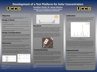
Calibration data was taken over a six hour period from 11:00 AM to 5:00 PM. Batteries were changed
out every hour in order to guarantee continuity of the calibration cycle. This trial was done to insure
that any offset between the two solar cells were accounted for would not skew the data in solar
concentrator trials. Figure 5 shows the power output of each solar cell plotted as a function of time
measured in minutes from when the test platform was turned on at 10:00 AM.
Objective Calibration
Acknowledgments
I would like to thank Dr. Stevens for giving me guidance and bearing with me during the trouble shooting process and all the guys in the
machine shop that helped during the design and fabrication process and my dad who helped me immensely with the electronics
troubleshooting.
References
"Adafruit TB6612 1.2A DC/Stepper Motor Driver Breakout Board." Adafruit. Web. 5 Jan. 2016. <https://learn.adafruit.com/adafruit-tb6612-h-
bridge-dc-stepper-motor-driver-breakout>.
Ada, Lady. "Adafruit Data Logger Shield." Data Logger Shield Overview. Web. 5 Jan. 2016. <https://learn.adafruit.com/adafruit-data-logger-
shield/shield-overview>.
Design Criteria
The test platform must be able to take data automatically at regular time intervals without being
prompted by the user.
The test platform must store data reliably over the course of a test cycle and store the information in
either excel or text format for later analysis.
The test platform must run off of batteries and run for 6 hours consecutively on a single charge from
the batteries
The test platform must be able to track the sun through at least 120° of motion.
The test platform must have an adjustable angle of elevation to compensate for the change in the axis
of rotation of the earth throughout the year.
Design Considerations
The change in the spin axis of the earth changes only 23.5° over the coarse of the year. Automating the
azimuth angle of the test platform would take a great deal of time and effort for very little benefit. Only
the latitude axis of rotation of the apparatus will be automated. The azimuth angle can be changed
manually.
The motor driving the rotation cannot run at the same time that the data acquisition system is taking
readings from the solar cells. This is done to increase the reliability of the readings by avoiding
variance in the current drawn from the battery created by the motor.
A mechanism must be utilized to sustain the angle of the solar cell fixture.
Electronics
Troubleshooting Improvements
The original design of the structure of the test apparatus was to be built completely out of aluminum
angle iron, rods, and a square center post. Aluminum was chosen because of it price and ease of
machining. Angle iron were chosen to make up the bulk of the test apparatus in order to build the
appropriate geometry for the solar cell fixture. The solar cell fixture need to have a surface that
extended upward in order for a shadow to be cast on one of the light dependent resistors when the solar
cell fixture was not at a position normal to the sun. See Figure 3 for solar cell fixture diagram.
When machining the apparatus, the thin aluminum angle iron pieces were not able to be welded
together. Instead the test apparatus was riveted together. The rod that the solar cell rotates on was
changed to a steel threaded rod and the triangular azimuth angle support was also changed to steel. The
solar cell fixture rod was changed to a steel threaded rod to more easily attach the fixed gear and a
stopper to hold the solar cell fixture away from the pivot point. The triangular back support was
changed to steel because steel is easier to weld than aluminum.
During the initial testing phase the real time clock (RTC) on the data logger shield shorted out. The
main symptom of the problem was that the code would not initialize and no variables would output
from the Arduino to the computer. Sections of the code were added until variables would output. The
test platform could still log data without the RTC, but has to capture data using relative time, meaning
that each reading is taken at specific time interval from the last reading.
The during final assembly of the test platform, the front post of the test apparatus would lean forward.
The problem was cause by the thin aluminum angle iron pieces that were used in construction in
conjunction with added weight of the steel threaded rod that was attached to the solar cell fixture and
that the aluminum was riveted together instead of welded as specified in the initial design. An
aluminum triangular brace was welded to the front post to remedy this issue.
Battery life was also considerably shorter than initially predicted, at and hour and a half instead of six
hours. This was cause by the stepper motor drawing current in order to hold the position of the solar
cell platform. In order to ensure continuity of the test cycle, the 9 Volt battery was changed out every
hour.
Figure 3. Solar cell fixture and sensor diagram.
Figure 4. Test platform final assembly. Photo courtesy of Jon Cheek
A worm gear and DC motor would have been a better choice to rotate the solar cell fixture. A stepper
motor draws current constantly in order to hold its position. This negatively effected the battery life of
the test platform and forced the user to change batteries which led to bad readings
A diode network attached to the motor would ensure that the a back EMF could not flow back into the
controller or distort the ground potential.
Capacitors could also be added to the solar cell outputs to smooth out fluctuations in the readings taken
by the Arduino.
A longer delay statement could be used to let any transient currents caused by start up decay before any
readings were taken.
The structure of the test platform could be improved by using thicker aluminum angle iron. This would
alleviate the issue of the front sagging and it would also make the aluminum easier to weld.
The solar cell fixture could also be improved by having a taller lip. This would allow the test platform
to sense smaller changes in the position of the sun more easily.
Figure 5. Power output of solar cells plotted as a function of time
Sensor 1 Sensor 2
In Figure 5 power is plotted as a function of time. The power output of both cell are mostly constant
throughout the day other than large power spikes. A relatively small rise in power output through the
day was expected because the energy density of the sunlight changes as photons from the sun travel
through differing distances of atmosphere depending on the angle of the earth in its rotation. Only a
small power output rise throughout the day is expected because the test platform holds the solar cells in
a direction normal to the sun in order to receive maximum sunlight and thus the maximum power over
the course of the day. The large power spikes are most likely the result of changing out the batteries.
This could be cause by a back electromotive force (EMF) when the apparatus when is on or off.
The average power offset of the cells was 0.5013 mW and had a standard deviation of 0.1717 mW
Figure 1 and 2. Voltage circuits for light dependent resistors (left) and solar cells (right)