1.
KINEMATIC AND DYNAMIC SIMULATION ANALYSIS OF
HIGHSPEED ARC CONTOUR CUTTING DEVICE
Compared with Flame Cutting Machining which has low efficiency, poor quality and complex
manipulating process, and Water Jet Machining which cannot handle difficulttoprocess materials,
WEDM(Wire Electric Discharge Machining) can solve the problem of machining difficulttoprocess
material with largethickness in aerospace, aviation and military field in a better way. However, the
lack of flushing which leads to insufficient chipremoval and inadequate electrode cooling makes the
electrode easy to damage or break. In addition, the thicker and harder the material is, the lower
efficiency WEDM can achieve. Therefore, to solve these problems and improve machining efficiency,
the team came up with a new machining method called Highspeed Arc Contour Cutting, and
designed the device corresponding to this method, Highspeed Arc Contour Cutting Device.
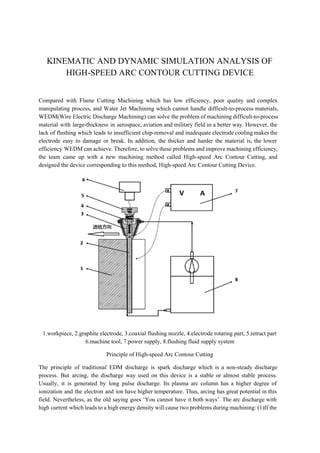
1.workpiece, 2.graphite electrode, 3.coaxial flushing nozzle, 4.electrode rotating part, 5.retract part
6.machine tool, 7.power supply, 8.flushing fluid supply system
Principle of Highspeed Arc Contour Cutting
The principle of traditional EDM discharge is spark discharge which is a nonsteady discharge
process. But arcing, the discharge way used on this device is a stable or almost stable process.
Usually, it is generated by long pulse discharge. Its plasma arc column has a higher degree of
ionization and the electron and ion have higher temperature. Thus, arcing has great potential in this
field. Nevertheless, as the old saying goes ‘You cannot have it both ways’. The arc discharge with
high current which leads to a high energy density will cause two problems during machining: (1)If the
2. discharge arc column lasts too long, it will burn the internal organization of the material and cause
damage to the workpiece which may result in machining failure. (2)There is only a hundredsmicrons
narrow discharge gap between the electrode and the workpiece. For large thickness workpiece, the
large amount of chip generated by electrolytic corrosion during the machining will accumulate and
jam the gap. Once those chip are not removed effectively, the circuit between electrode and workpiece
will short immediately and the cutting process will fail.
Aiming at solving these two problems, Highspeed Arc Contour Cutting Device can interrupt arc
effectively and remove chip efficiently using the following two methods. First one is Mechanical
Kinematic Arc Interruption Method which is implemented by electrode rotation combined with
reciprocation generated by two motors separately. The mechanism behind this method is that
electrode movement along the tangential direction of the arc weakens the arc column, even pulls it off.
The other method is Fluid Dynamic Arc Interruption Method which is implemented by coaxial
flushing. There will be an offset of the arc column along the direction of flow if there is a highspeed
flow field with at least 10m/s in the gap. When the length of arc increases, the impedance increases as
well. Once the impedance is large enough that discharge can no longer maintain, the arc column will
be interrupted. Taking advantage of these two methods, duration and intensity of the arc discharge can
be controlled strictly to avoid longlast arc column so that the damage caused by arc discharge can be
reduced to a minimum value.
During the initial machining experiments, we found that graphite electrodes fractured a lot of times
which is an unexpected problem. Resonance is a very likely reason. So what is done in the following
paper is to build the model of the device and find out its nature frequency and mode shape in order to
check whether resonance is the reason or not. The final goal is to verify the reasonability of the device
design and the feasibility of the machining process.
Analysis Process
Highspeed Arc Contour Cutting Device includes four parts: reciprocating motion part(black and
green parts), electrode rotating part(red part), highspeed flushing part(no show) and electrode
tipclamping part(yellow part). Reciprocating motion part and electrode rotating part need to realize
rotation and reciprocation compound movement of the electrode(blue part) which means the electrode
could move in a reciprocating way perpendicular to the feed direction and rotating around its axis with
3. high speed. The highspeed flushing part makes sure sufficient flushing on the electrode during
machining. The electrode tipclamping part limits the motion of the electrode and ensures it would not
have eccentricity and deflection.
Device Model
In the kinematic simulation part, the whole device is modeled and assembled by NX Unigraphics.
According to the result of interference analysis, modify and optimize the slider part, screw part and
the electrode tipclamping part because of their inappropriate designs including wrong size and shape
and unreasonable assembly way. Set pairs for the device according to the way it moves in real. Do
trajectory simulation and kinematic analysis for the device model based on its movement in actual
machining process to verify that the electrode rotation and reciprocation compound movement is
feasible. Find the relation between the rotating speed of the motor and the reciprocating speed of the
screwnut since if the reciprocating speed is known, the rotating speed can be calculated. With the
help of NX function editor, input reciprocating motion to the model with different forms and compare
their advantages and disadvantages. As the trajectory simulation shows, a step input for reciprocating
motion is workable but not good. It will cause vibration and damage to the motor because the rotator
has to rotate to an opposite direction instantly. A simple harmonic form is better with which the
motion of the whole device is smooth and reasonable. Thus, on the basis of this kinematic simulation,
a simple harmonic function like movement for the reciprocation is recommended.
In the dynamic simulation part, a dynamic model is established first based on the kinematic mode.
Then, constraints are added on the model according to real device. Optimize the pulley system and
bearing model. Then, optimize some of those constrains for a better dynamic simulation result as well.
Set material type for all parts so that ADAMS could calculate the mass. Do trajectory simulation
again to make sure the new model is correct. Use ADAMS/Linear and ADAMS/Vibration modules to
analyse the natural frequency and mode shapes of the device. There are sixteen different orders of
modes which are meaningful among all two hundred and fourteen modes. We can neglect other modes
which are over damping since over damped system has no vibration before returning to equilibrium
state. Among these sixteen meaningful modes, we will see that the first seven modes are related to the
electrode according to the animation results. The other nine modes only relate to the belt system
which has no influence to the electrode. Next step is to analyse frequency response of the electrode
and resonance situation under different excitations such as different direction excitations, different
4. location excitations and different form excitations. In addition, compare the influence of using
electrode tipclamping device or not, simulate the effect of eccentricity and deflection of the electrode.
As the analysis results show, a recommended working rotating speed range is from 600rpm to
6000rpm. It is not hard to find that the actual working rotating speed range which is from 800rpm to
3000rpm is included in this safe range and it does not overlap with any natural frequency of the
device. So it proves that there is no resonance going to happen during machining and the design of
this device is reasonable. Also deflection is proved to be an important influence which may lead to
poor machining quality. Therefore, using electrode tipclamping part in the real machining process is
highly recommended.
After that, a real machining experiment is conducted to compare the results with simulation under
different conditions. The first experiment sets working current as 200A and the cutting depth as 2mm
with feeding speed 0.25mm/min. During the machining, the discharge is not continuous because of
the low feed rate. There is no circuit short happening since the electrode got adequate flushing fluid.
But the end of the electrode is overheated and turns red. Because the cutting which has low feed rate
and discontinuous discharge is not deep inside the workpiece, there is only a small amount loss of the
graphite on electrode, and the workpiece surface after machining is smooth without erosion. For the
second experiment, those three parameters mentioned before are set larger and the discharge process
becomes continuous. Then, a ten millimeter deep groove machining on 45# steel with fiftyfive
millimeter thickness is realized. It successfully verifies the feasibility of the highspeed arc contour
cutting method as well as the reasonability of the design of the device. However, during the
experiment, the deflection on the tip of the electrode does influence the machining quality which is
the same with what theoretical simulation result shows. So the electrode tipclamping device should
be used in order to avoid unnecessary vibration. What’s more, a simple vibration experiment is
conducted and it verifies that there is no resonance in the range of working rotating speed.
As regard to the whole research of this device, my work is just a beginning. From design to testing,
from optimization to real product, there is still a long way to go. What is done in this paper is to prove
resonance is not the reason of electorde fracture and verify the reasonability of the device design and
the feasibility of the machining process, so that people could keep working on the study of this device.
Except the results have already showed, there is something else which is worth to consider and use for
reference in the further research. First of all, even though this research helps a lot on optimizing
highspeed contour cutting device, comparing with the actual complex machining situation, some
errors exist in the entire simulation process. So applying results or implementing data should be
careful rather than blindly follow. Second, whenever update the structure of the device, such as
installing retract part in the latest optimizing, both kinematic and dynamic simulation should be run
again to make sure the new part will not lead to any poor performance. In addition, a rigidflexible
hybrid modeling could be used in the future analysis so that the simulation result could be better.