
Recommended
Recommended
More Related Content
What's hot
What's hot (20)
Similar to Experimental and Numerical Modal Analysis of a Compressor Mounting Bracket
Similar to Experimental and Numerical Modal Analysis of a Compressor Mounting Bracket (20)
More from IOSRJMCE
More from IOSRJMCE (20)
Recently uploaded
Recently uploaded (20)
Experimental and Numerical Modal Analysis of a Compressor Mounting Bracket
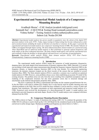
- 1. IOSR Journal of Mechanical and Civil Engineering (IOSR-JMCE) e-ISSN: 2278-1684,p-ISSN: 2320-334X, Volume 14, Issue 1 Ver. VI (Jan. - Feb. 2017), PP 01-07 www.iosrjournals.org DOI: 10.9790/1684-1401060107 www.iosrjournals.org 1 | Page Experimental and Numerical Modal Analysis of a Compressor Mounting Bracket Avadhesh Meena1 - CAE Analyst (avadesh.iitd@gmail.com) Somnath Sen2 - CAE/CFD & Testing Head (somnath.sen@subros.com) Vishnu Suthar3 - Testing Analyst (vishnu.suthar@subros.com) Subros Ltd. Noida-201304 Abstract: Experimental modal analysis has grown steadily in popularity since the advent of the digital FFT spectrum analyzer in the early 1970’s. Today, impact testing (or bump testing) has become widespread as a fast and economical means of finding the modes of vibration of a machine or structure. In this paper, it presents the experimental and numerical modal analysis of a compressor mounting bracket (CMB). The dynamic behavior of CMB is investigated through impact testing. The three-dimensional finite element models are constructed using Altair HyperMesh and an numerical modal analysis is then performed to generate natural frequencies and mode shapes in the three-orthogonal directions. The finite element model agrees well with the experimental tests and eventually it helps the designer to design upfront with much lesser cost and time of experimentation. Keywords: Experimental modal analysis (EMA), finite element analysis (FEA), FFT (Fast Fourier Transformation), Compressor mounting bracket (CMB). I. Introduction The experimental modal analysis (EMA) means the extraction of modal parameters (frequencies, damping ratios, and mode shapes) from measurements of dynamic responses (Rao, 2004). Basically, it is carried out according to both input and output measurement data through the frequency response functions (FRF) in the frequency domain, or impulse response functions (IRF) in the time domain. For mechanical engineering structures, the dynamic responses (output) are the direct records of the sensors that are installed at several locations (Ren, 2004). The finite element analysis (FEA) is currently a common way to perform an analytical modal analysis of CMB. However, some problems always occur when establishing an accurate FE model of the existing structure. The problem arises not only from the errors resulting from simplified assumptions made in modeling of the complicated structures but also from parameter errors due to structural damage and uncertainties in the material and geometric properties (Ren, 2004). The FEA is analytical, the EMA is experimental and modes are the common ground between the two. In fact the EMA is still used to validate FEA models, but it is also heavily used for trouble shooting noise and vibration problems in the field. Once an FEA model has been validated, it can be used for a variety of static and dynamic load simulations. This paper concentrates on both experimental and numerical modal analysis of a CMB. Numerical work involved the development of a three-dimensional FE model. A modal analysis was performed to provide frequencies and mode shapes. Results of the FE modal analysis were compared with those obtained from the EMA. II. Compressor Mounting Bracket Description The CMB as shown in Figure 1 is made of aluminium die casting (ADC-12). To construct the geometry of the CMB, NX UG software is used to build up the 3-D CAD Model for the simulation based on the feasibility study carried out in earlier design stages. Mechanical and Physical Properties are shown below in Table 1. Figure 1. Facade view showing the CMB
- 2. Experimental and Numerical Modal Analysis of a Compressor Mounting Bracket DOI: 10.9790/1684-1401060107 www.iosrjournals.org 2 | Page Table-1. Mechanical and Physical Properties of CMB Material Name & Grade Young's Modulus (GPa) Yield Stress (MPa) Density (Kg/m3) Poisson's Ratio (μ) Aluminum Alloy (ADC-12) 71 165 2820 0.33 III. Finite Element Modeling Now that the geometrical and mechanical properties of the CMB are available, we can proceed with the finite element modeling. Three-dimensional linear elastic finite element model has been constructed using Altair HyperMesh FEA software. The CMB is modeled using solid ten-noded tetrahedral elements (each node has 3 degrees of freedom UX, UY and UZ). Figure 2. The ten-noded tetrahedral solid element Figure 3 shows the 3D finite element model of the CMB using tetrahedral solid element: Figure 3. The finite element model of the CMB The full model has a total of 2,00,883 tetrahedral solid elements with more than 3,23,688 nodes. The unit mesh size is 2mm. The fine mesh is used to capture the features of rib and chamfer on CMB. The mesh quality parameters (like: aspect ratio < 5, jacobian > 0.6, tet collapse > 0.5 and duplicates) has been maintained to get the accurate results. The EIGRL card is used to extract the eigenvalue and eigenvectors up to first 10 modes using Lanczos method. The CMB is analyzed in free-free position using Optistruct solver and verify the same with Nastran solver, so rigid body modes are expected in the results. First six modal frequencies less than 20 Hz are observed during analysis & assumed as rigid body modes. With 4 modes to extract, the results of the modal analysis are shown in Table 2. Table-2. Calculated modal frequencies from the FEA Mode # Modal FEA Frequencies (Hz) Mode Shape Descriptions 1 969.9 First Twisting 2 1088.8 First In-Plane Bending 3 2095.8 First Out-Plane Bending 4 2135.5 Second Out-Plane Bending
- 3. Experimental and Numerical Modal Analysis of a Compressor Mounting Bracket DOI: 10.9790/1684-1401060107 www.iosrjournals.org 3 | Page The mode shapes of the CMB are shown in Figure 4 sorted from the lowest frequency to the highest: (a) f1 = 969.9 Hz (b) f2 = 1088.8 Hz (c) f3 = 2095.8 Hz (d) f4 = 2135.5 Hz Figure 4. Mode shapes of the CMB IV. Experimental Modal Analysis (EMA) EMA has grown steadily in popularity since the advent of the digital FFT (Fast Fourier Transformation) spectrum analyzer in the early 1970’s (Schwarz & Richardson). In this paper, we will make FRF measurements with a FFT analyzer, modal excitation techniques, and modal parameter estimation from a set of FRFs (curve fitting). Experimental modal parameters (frequency, damping, and mode shape) are also obtained from a set of FRF measurements. The FRF describes the input-output relationship between two points on a structure as a function of frequency. Since both force and motion are vector quantities, they have directions associated with them. Therefore, an FRF is actually defined between a single input D.O.F. (point & direction), and a single output D.O.F.
- 4. Experimental and Numerical Modal Analysis of a Compressor Mounting Bracket DOI: 10.9790/1684-1401060107 www.iosrjournals.org 4 | Page Figure 5. Time and Frequency Domain FRF is defined as the ratio of the Fourier transform of an output response [X()] divided by the Fourier transform of the input force [F()] that caused the output (See Figure 5). An FRF is a complexed valued function of frequency. Actually FRF measurements are computed in a FFT analyzer. V. Exciting Modes with Impact Testing With the ability to compute FRF measurements in an FFT analyzer, impact testing was developed during the late 1970’s and has become the most popular modal testing method used today. Impact testing is a fast, convenient, and low cost way of finding the modes of machines and structures. All the tests were performed at inhouse installed facility. The following equipment's are required to perform an impact test: 1. An impact hammer with a load cell attached to its head to measure the input force (Figure 9). 2. An accelerometer to measure the response acceleration at a fixed point & direction (Figure 10). 3. A 4 channel FFT analyzer to compute FRFs. 4. Post-processing modal software for identifying modal parameters and displaying the mode shapes. Figure 6. CMB suspended on elastic cables and accelerometer mounting location The whole process of the impact testing is depicted in Figure 7. Figure 7. The process of the impact testing
- 5. Experimental and Numerical Modal Analysis of a Compressor Mounting Bracket DOI: 10.9790/1684-1401060107 www.iosrjournals.org 5 | Page In general a wide variety of structures and machines can be impact tested. Of course, different sized hammers are required to provide the appropriate impact force, depending on the size of the structure; small hammers for small structures, large hammers for large structures. In this experiment, the CMB is suspended on elastic cables as shown in Figure 6, so that rigid body modes have very small frequencies compared to those of the deformation modes. Fixing the accelerometer at a single DOF as shown in figure 6, the CMB was impacted by hammer at many DOF to excite all modes (see Figure 11 for the position and directions of all DOF). After every impact the measurements were taken and saved. The software used is LMS® (Leuven Measurement System). From the measured FRFs, the software evaluates natural frequencies and mode shapes as well as damping ratios, but the latter are not shown. Table 3. lists the measured frequencies from the EMA using LMS software. Table-3. Measured frequencies from the EMA Mode # Modal EMA Frequencies (Hz) 1 955 2 1062 3 2056 4 2092 Figure 8. Frequency vs Acceleration Plot using LMS software VI. Roving Hammer Test A roving hammer test is the most common type of impact test. A Dytran Impulse Hammer as shown in figure 9 is used to impact the structure. The technical specifications of hammer are shown below. In this test, the accelerometer is fixed at a single D.O.F., and the structure is impacted at as many D.O.F.s as desired to define the mode shapes of the structure. Using a 4-channel FFT analyzer, FRFs are computed one at a time, between each impact D.O.F. and the fixed response D.O.F. An impact tip of aluminium material is used to impact the structure. Technical Specification of Dytran Impulse Hammer are :- Model No :- 5800B3 Sensitivity :- 10.12 mV/N Figure 9. DYTRAN Impulse Hammer used for testing EMA
- 6. Experimental and Numerical Modal Analysis of a Compressor Mounting Bracket DOI: 10.9790/1684-1401060107 www.iosrjournals.org 6 | Page VII. Roving Tri-axial Accelerometer Test When 3D motion at each test point is desired in the resulting mode shapes, a roving tri-axial accelerometer is used and the structure is impacted at a fixed D.O.F. with the hammer. Since the tri-axial accelerometer must be simultaneously sampled together with the force data, a 4-channel FFT analyzer is required instead of a 2-channel analyzer. Figure 10. DYTRAN Triaxial Accelerometer used for testing EMA Technical Specification of Dytran Triaxial Accelerometer are:- Model No :- 3023A Sensitivity :- 9.98 mV/g @ Point #1 :- 9.22 mV/g @ Point #2 :- 10.02 mV/g @ Point #3 Range :- 500g Freq. Range :- 1.5 to 10,000 Hz (+15/-5%) Features :- Triaxial, Adhesive mount, Lightweight, Hermetic, Titanium and 4-pin radial connector. VIII. Results and Comparison The FE numerical modal analysis was validated by EMA in terms of natural frequencies and mode shapes. Theoretically, a perfect model would match all experimentally determined mode shapes and frequencies exactly. In reality it is never be a perfect match between all numerical and measured modal properties. Therefore, only the most structurally significant modes and frequencies are used in the comparison process. Table 4 summarizes the frequencies of both the methods, EMA and FEA with the percentage difference between the frequencies of both the methods for the given mode. Table-4 Frequencies (Hz) from both methods (EMA and FEA) Mode Frequencies EMA (Hz) Frequencies FEA (Hz) Difference 1 955 970 1.55 2 1062 1088 2.39 3 2056 2095 1.86 4 2092 2135 2.01 IX. Conclusions Modern experimental modal analysis techniques have been reviewed in this paper. The numerical modal analysis with 3D finite element models of the CMB is compared with the EMA. The results from finite element model agree well with the experimental results. This model is suitable for the dynamic analysis of the CMB. However with minor fine-tuning it can be extended to other components as well. The validated finite element model can be used for further dynamic analysis and evaluation of structural performance from loadings. Acknowledgment The authors would like to acknowledge our Design, Prototype and testing teams for extending their kind support. The authors would also like to thank the R&D Head Mr. A. K. Jaiswal and CAE/CFD & Testing Head Mr. Somnath Sen for providing this opportunity for publishing the work.
- 7. Experimental and Numerical Modal Analysis of a Compressor Mounting Bracket DOI: 10.9790/1684-1401060107 www.iosrjournals.org 7 | Page Appendix In this appendix: Figure 11. shows the impact points (1 to 7 DOF) on the CMB Figure 11. shows a 3D view of the position of the impacted points Figure 11. A 3D view of the position of some impacted points (here only points 1,2,...7 are shown) References [1]. Ewins, D. J. (2000). Modal testing: Theory and practice, Research Studies Press Ltd., Hertfordshire, U.K. [2]. Maia, N. M. M., and Silva, J. M. M., eds. (1997). Theoretical and experimental modal analysis, Research Studies Press Ltd., Hertfordshire, U.K. [3]. Ramirez, R. W. (1985). The FFT: Fundamentals and Concepts, Prentice Hall. [4]. Rao. (2004). Mechanical Vibrations, 4 th Edition. [5]. Ren, Wei-Xin (2004). Experimental and Analytical Modal Analysis of Steel Arch Bridge. Journal of structural Engineering ASCE [6]. Richardson, M (2005). Modal Analysis versus Finite - Element Analysis [7]. Schwarz, B & Richardson M, Experimental Modal Analysis, CSI reliability week, Orlando,(1999)