
Recommended
Recommended
More Related Content
What's hot
What's hot (20)
Viewers also liked
Viewers also liked (10)
Similar to measurement
Similar to measurement (20)
Recently uploaded
Recently uploaded (20)
measurement
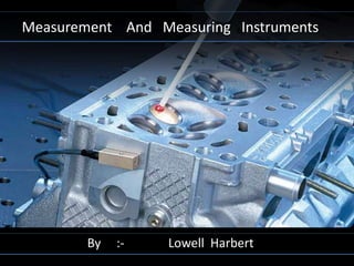
- 1. Measurement And Measuring Instruments By :- Lowell Harbert
- 2. What is measurement? Ans. Whatever in this world exist in some amount and determination of this amount is called measurement. Basically , there are 3 standards of length measurement :- a. Line standard. b. End standard. c .Light wave length standard.
- 3. a. Line standard :- when the length being measured is expressed as the distance between two lines this is known as line standard. example:- measurement of length with a scale. b. End standard :- when the length being measured is expressed as the distance between two surfaces or ends is known as end standard. example :- measurement with micrometer and slip gauges . c. Light wave length standard :- Because of problem of variation in length of metallic standards such as meter and ….
- 4. … yard wave length of light has been internationally considered which defines the primary standard . the wave length of monochromatic light [red radiation] from krypton isotope 86 is used as the unit of length . eleventh general conference of weight and measurement held in Paris in 1960 defined the meter as, “The meter is equal to 1650763.73 wave length of the red range radiation of krypton isotope 86 (kr-86) gas.”
- 5. •Meter and yard are replaced by natural atomic standard of light . •1m = 1650763.73 wave length •1mm = 1650763.73/1000 wave length •1inch = 1650763.73*25.4/1000 wave length •1yard = 1650763.73*25.4*36/1000wave length
- 6. micrometer , Vernier and rules are calibrated by slip gauges and slip gauges are calibrated against the laser by the N.P.L .
- 7. Definition of Accurate (from dictionary) Free from error especially as the result of care Able to give an accurate result .
- 8. What happens if you do not measure accurately?
- 9. 1. Basic Vernier Caliper 2. Long Jaw vernier caliper 3. Knife Edge Vernier caliper 4. Chiesel Shape Vernier Caliper
- 10. Dial Vernier Caliper Digital Vernier Caliper Digital Depth Vernier Caliper
- 11. Outside Micrometer Inside Micrometer Depth Micrometer Can you identify the metric micrometer ?
- 12. Telescopic Gauges Spring loaded Measure large inside dia.
- 13. Dividers or Caliper Instrument that consists of two adjustable legs or jaws for measuring the dimensions of material parts. Outside calipers measure thicknesses and outside diameters of objects; inside calipers measure hole diameters and distances between surfaces.
- 15. Coordinate Metrology Coordinate metrology is a field of metrology that is becoming increasingly popular in the manufacturing industry. Coordinate metrology enables the three-dimensional measurement to be carried out on complex object in a single setup. The instrument used for this purpose is known as the coordinate measuring machine or CMM. In general, the CMM comprises three frames that move along three orthogonal axes, i.e. X-, Y- and Z-axis. Usually, a contact device known as measuring probe is attached to the end of the Z-axis. The displacement along each axis is measured by a linear measurement system and the readings are sent to an electronic controller. The electronic controller is connected to a computer that also enables various types of data processing to be performed. Repeated measurements on similar objects can be done easily by programming the motion of the axes of the machine. This reduces the time taken for measurement and inspection up to 80% to 90%. These machines are made in various sizes and the methods of operation are based on either manual or computer-aided.
- 17. Types of CMM The basic CMM consists of three axes, each provided with a guide way that enable precise movement along a straight line. Each guide way has a carrier that moves along. The carrier enables the second carrier to move along a straight line based on the first guide way. Each axis is fitted with a precision scale that records the position of the carrier measured from a reference point. The measuring probe is fitted to the carrier on the third axis. When the measuring probe touches the object being measured, the measurement system records the
- 18. position of all three axes. There are several physical configurations of CMMs. All the configurations have a method of moving the probe along three axes relative to the object. Although there are many designs of CMMs but they can be grouped into five basic types as follows: (a) Cantilever type, (b) Bridge type, (c) Horizontal arm type, (d) Column type and (e) Gantry type
- 19. Cantilever type CMM The schematic diagram of the cantilever type CMM is shown in Figure. In the cantilever type CMM the measuring probe it attached to the Z-axis and moves in the vertical direction. The Z-axis carrier is fitted to the cantilever arm and provides movement in the Ydirection. The Z-axis movement is provided by the table. This type of CMM design provides easy access to the work area and has high workspace volume.
- 20. Bridge type CMM In principle, the bridge type CMM has a moving bridge as shown in Figure 7.2. The measuring probe is fitted to the Z-axis arm and the Z-axis carrier is fitted to the X-axis arm. The X- axis carrier in turn is fitted to the Y-axis arm. Both ends of the Y- axis are supported on the table, usually using air bearings. This type of design provides better
- 21. rigidity and thus the CMM has higher accuracy compared to the horizontal arm type. The weakness of this design is that it is difficult to place work onto the table because of the obstruction from the vertical parts of the Y-axis frame. However, this design is one of the most popular.
- 22. Column type CMM The design of the column type CMM is similar to the drilling machine or the vertical milling machine (see Figure). This type of CMM is commonly known as the universal measuring machine. The construction of the column type CMM provides very good rigidity
- 23. Horizontal arm type CMM The horizontal arm type CMM has a horizontal arm that moves in the horizontal direction (Figure). The measuring probe is fitted to the Y-axis arm and not the Z-axis arm as in the other designs of CMM. The main advantage of this type of CMM is that the work volume is large and free from obstruction. This type of machine can be used for large work piece such as a car body.
- 24. Gantry type CMM In the gantry type CMM the X and Y-axes are placed overhead and supported by four columns from the base as shown in Figure . The main advantage of this type of construction is that the operator can move with the probe and measurement on large objects, such as the body of car, can be carried out.
- 25. Types of probes and sensor system All CMMs have one or more probes and a method of moving them along three orthogonal axes relative to the workpiece. Most the probes used currently are the ‘soft’ or touch sensitive types. These types of probes use electronic mechanism to break the circuit when contact between the probe and workpiece occurs. Several types of touch probes are available and the type selected depends on the workpiece material and dimension to be measured. All of these can be grouped into three types as follows: (a) Ball type probe These are standard type probes used in CMMs and have various applications (Figure (a)). (b) Tapered probe These are used for determining the location and diameter of holes (Figure (b)). (c) Cylindrical probe The cylindrical probes are used to measure thin plates (Figure (c)).
- 26. The sensor system commonly used in the touch sensitive probes is the circuit breaker type shown in Figure In this type of sensor system an arrangement of spheres and rods are used to keep the flow of current in the sensor circuit. When the probe end touches the surface of the workpiece, deflection of the probe will occur and this will cause one of the spheres to be lifted and thus break the sensor circuit. The position of all three axes is frozen momentarily when this occurs and the value of the readings of the linear measurement system is transferred to the controller or computer.
- 27. Engg. Drawing of engine head
- 28. CMM REPORT OF ENGINE HEAD
- 29. Thank you
Editor's Notes
- 1