
Recommended
Recommended
More Related Content
What's hot
What's hot (16)
Similar to Simulation and Analysis of Electrolyte Flow Pattern in ECM for L-Shaped Tool Using CFD
Similar to Simulation and Analysis of Electrolyte Flow Pattern in ECM for L-Shaped Tool Using CFD (20)
More from IOSRJMCE
More from IOSRJMCE (20)
Recently uploaded
Recently uploaded (20)
Simulation and Analysis of Electrolyte Flow Pattern in ECM for L-Shaped Tool Using CFD
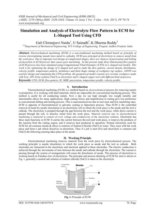
- 1. IOSR Journal of Mechanical and Civil Engineering (IOSR-JMCE) e-ISSN: 2278-1684,p-ISSN: 2320-334X, Volume 14, Issue 1 Ver. V (Jan. - Feb. 2017), PP 70-74 www.iosrjournals.org DOI: 10.9790/1684-1401057074 www.iosrjournals.org 70 | Page Simulation and Analysis of Electrolyte Flow Pattern in ECM for L-Shaped Tool Using CFD Gali Chiranjeevi Naidu1 , U Sainadh2 , K Dharma Reddy3 123 Department of Mechanical Engineering, SVU College of Engineering, Tirupati, Andhra Pradesh, India Abstract: Electrochemical machining (ECM) is a non-traditional machining method based on principle of reverse electroplating (anode loses metal to cathode). ECM uses principal of electrolysis to remove metal from the work piece. Due to improper tool design of complicated shapes, there are chances of passivation and boiling of electrolyte in ECM process that causes poor machining. In this present study three dimensional flow pattern of ECM process has been simulated using Computational Fluid Dynamics (CFD) in L-shaped tool models. This work is for optimizing the design of L-shaped tool and to study the flow pattern, current density distribution, velocity profile, temperature pattern, turbulence and final shape change of workpiece top surface. ANSYS was used for design and simulating this CFD problem, the geometrical model consists of a circular workpiece made with Iron, 20% brine solution (NaCl) as electrolyte and L-shaped copper tool with different kind of grooves. Keywords: CFD, ECM, flow pattern; IE, MRR, passivation, temperature profile, velocity profile. I. Introduction Electrochemical machining (ECM) is a method based on electrochemical process for removing metals in production. It is working with hard materials which are impossible for conventional machining process. This method is useful for all conducting metals. Now a day we use high strength, low weight metallic and intermetallic alloys for many applications. High cutting forces and imperfection in cutting give low preference to conventional milling and turning process. This is uneconomical too due to tool wear and low machining rates. ECM is opposite of electrochemical or galvanic coating or deposition process. Thus ECM is the controlled removal of metal by anodic dissolution in an electrolytic cell in which the work piece is the anode and the tool is cathode. The electrolyte is pumped through the gap between the tool and the work piece, while direct current is passed through the cell, to dissolve metal from the work piece. Material removal rate in electrochemical machining is analyzed in context of over voltage and conductivity of the electrolyte solution. Electrolyte has three main functions in ECM: It carries the current between the tool and work piece, it removes the products of the reaction from the cutting region, and it removes heat produced in operation. Normal electrolyte used for ECM for all common metals & alloys is solution of Sodium Chloride (NaCl) in water. They react with the work piece and form a salt which dissolves in electrolyte. Thus if a job is steel (Fe) and electrolyte is common salt (NaCl) the following reacting takes place at the anode. II. Working Principle Electrochemical machining removes material from the work piece by electrochemical process. The working principle is anodic dissolution in which the work piece as anode and the tool as cathode. Both electrodes are immersed in the electrolyte and electrical applied to these electrodes. The electric conduction is achieved through the movements of ions between the anode and cathode through the electrolyte. The current is passing through the system of arrangements will cause the dissolution of anode. This process of electrolysis is working based on Faradays law of electrolysis. The principal and process detailing of ECM for steel is shown in Fig. 1, generally a neutral salt solution of sodium chloride (NaCl) is taken as the electrolyte. Fig. 1: Principle of ECM
- 2. Simulation and Analysis of Electrolyte Flow Pattern in ECM for L-Shaped Tool Using CFD DOI: 10.9790/1684-1401057074 www.iosrjournals.org 71 | Page 1.1. Power Supply Power supply is required with low value of voltage and high value of current. Current of the order of 1000- 40,000 A is generally required and 5-25 V is applied to overcome the resistance at the gap. 1.2. Servo System The servo system controls the tool motion relative to the work piece to follow the desired path. It also controls the gap width within such a range that the discharge process can continue. If tool moves too fast and touches the work piece, short circuit occurs. Short circuit contributes little to material removal because the voltage drop between electrodes is small and the current is limited by the generator. If tool electrode moves very slowly, the gap becomes too wide and electrical discharge never occurs. 1.3. Tool Feed Rate In ECM process, an inter electrode gap of about 0.01 to 0.05 mm is maintained between the tool and work piece. For smaller gap, the electrical resistance between the tool and work-piece is least and the current is the maximum and accordingly maximum metal is removed. The tool is feed in to the work-piece depending upon how fast the metal is to be removed. The movement of the tool slide is controlled by a hydraulic cylinder giving some range of feed rate. 1.4. Electrolyte Flow Rate Electrolyte flow is a very important and critical parameter in the analysis of electrochemical machining. Insufficient and improper electrolyte flow in the IEG may cause poor machining. The effect of cavitation, stagnation, and vortex flow can avoid up to a certain extent by avoiding sharp corner. The entire flow path has an approximate radius of 0.7 to 0.8 mm. Flow will not cover all area of the work-piece initially. These difficulties can be avoided by using restriction techniques. Fig. 1.2 shows a tool with no sharp corners. 1.5. Material Removal Rate Material removal rate (MRR) is the rate at which the work-piece material is dissolved per unit time. It is primarily a function of feed rate which signifies the current passed between the work-piece and the tool. As the tool advances towards work, inter electrode gap decreases and current increases which cause more metal removal at a rate corresponding to the tool advance. A stable spacing between the tool and work is thus established. It may be noted that high feed rate not only is productive but also produces best quality of surface finish. III. Modelling And Simulation The analysis techniques, geometric modeling and boundary conditions are explained in this chapter. ECM set up consists of a work-piece, tool and an electrolyte solution. Work-piece should be electrically conducting material and the tool may or may not be. Commonly used electrolytes are NaCl solution and NaNO3. To get required shape in the work-piece, tool should be designed properly. The shape of the tool affects the critical parameters of machining. Another important aspect in the modelling of ECM is the flow pattern of electrolyte and the various intervening factors those are affected by the two phase flow pattern of electrolyte. 1.6. Geometrical Modelling Finite element based commercial CFD software package, ANSYS, which operated under the Windows7 64-bit operating system, was used for the simulation study. In the present simulation process, the modelling is done with ANSYS design modeler Module of ANSYS software. The L shaped tool with central through hole model is used for the simulation study. The initial shape of the work-piece is circular in shape with 60 mm diameter and 20 mm height. Model of work-piece is shown in Fig. 2. Electrolyte used for this simulation is brine solution (15% NaCl). The electrolyte starts flowing with a constant diameter of 3 mm from the inlet of the tool. The long side of the L-shape is having 30 mm length and short side of 15 mm length and the central hole has diameter of 3mm. Top view of the tool is shown in Fig. 3 and 3D view is shown in Fig. 4. Inter electrode gap (IEG) for all the models is kept constant at 0.5 mm. The key dimensional feature of the physical model is as shown in table 1. The complete physical model of workpiece tool set up is as shown in Fig. 5.
- 3. Simulation and Analysis of Electrolyte Flow Pattern in ECM for L-Shaped Tool Using CFD DOI: 10.9790/1684-1401057074 www.iosrjournals.org 72 | Page Table 1: Element type Sl.No Component Material Physical state Shape Dimension(mm) 1 Work-piece Iron Solid Cylindrical 60 dia. X 20 ht. 2 Tool Copper Solid L-shaped Arm 30 X Width 15 X Height 50 X central hole 3Ø 3 Medium Brine Fluid - - 1.7. L-Shaped Tool with Central Through Hole A simple L shaped model having a central through hole with a diameter of 3mm and height of 50 mm. This centre of the hole is fixed on (-7.5,-7.5) coordinate in the XZ plane. Fluid is flowing through the through hole and flow out through the IEG. Top view of the tool is shown in Fig. 3 and 3D view is shown in Fig. 4. Inter electrode gap (IEG) is kept constant as 0.5mm. 1.8. Meshing Model is meshed using ANSYS Mesh Module in ANSYS commercial software. The quality of mesh is a relevant factor in the case of appropriate geometry of the model and accuracy of the results. This can be expressed in terms of orthogonal quality. If the value of orthogonal quality is coming near to one then our mesh quality is good and it gives better results. At the same time if it is coming near to zero, then the mesh gives bad results. Advantages of this method is that it uses the geometry only to associate the boundary faces of the mesh to the region of interest there by ignoring gaps, overlaps and other issues that present in other meshing tools. However, the required timing of simulation for the finer meshes was found to be 35% higher than intermediate mesh and 190% higher than the coarse mesh. Materials used are copper for tool, iron for work piece and brine (15% NaCl) as the electrolyte solution. 1.9. Boundary Conditions Before considering the boundary conditions, the computational domains should be specified. In this simulation three domains are being used such as two solid domains and a fluid domain. One solid domain for work-piece and other is for tool. Materials of solid domain are considered as pure solids. Morphology of materials in the solid domain is given as continuous solid and reference temperature is given 298K. Electric potential model with automatic value is chosen from Electromagnetic model. Fluid domain is constructed for electrolyte. Two materials are taken for fluid domain as it is a two phase flow analysis. Morphology for fluid domain is taken as continuous fluid for brine and dispersed fluid for hydrogen bubbles. The properties of the materials used in these domains are set as per the values in the Table 2.
- 4. Simulation and Analysis of Electrolyte Flow Pattern in ECM for L-Shaped Tool Using CFD DOI: 10.9790/1684-1401057074 www.iosrjournals.org 73 | Page Table 2: Material properties IV. Results And Discussions The analysis of the results and discussion of the model generated in ANSYS as per the modelling. It shows the crucial parameters affecting overall machining process of ECM in terms of contours from which we can predict the variation of these parameters in the IEG and their effects. 4.1. Critical Parameters Analysed In Simulation 4.1.1. Volume Fraction Profile Fig. 6 shows the volume fraction profiles of the model generated. The inlet velocity for this simulation study was taken as 40 m/s. The volume fraction contour has shown the volume fraction of brine in the homogenous mixture of continuous fluid brine and a dispersed fluid hydrogen bubble. 4.1.2. Velocity Profile Fig.7 show the velocity profile for model respectively with an inlet velocity of 40 m/s, which indicates that velocity of two phase electrolyte is increased from the groove to the boundary partly due to reduction in area of flow and partly due to formation of hydrogen bubbles resulting in more turbulence. 4.1.3. Pressure Profile The pressure profiles describe about the variation in pressure in the IEG on the plane of machining area. As in model, there is very large amount of production of hydrogen bubbles and because of cavitation effect, the pressure increases at a large number of nucleus sites from the groove outlet towards the outer boundaries showing the places of hydrogen bubbles and hence high pressure zones as shown in Fig. 8. 4.1.4. Temperature Profile Pattern is a very crucial aspect for this study. As can be seen from the Fig. 9, the temperature is least at the groove outlet and goes on increasing rapidly as we move to outside for model. It crosses the boiling point of brine which in turn produces phase change and production of hydrogen bubbles as secondary dispersed phase. Properties Brine Copper Iron Air Molar mass (kg/kmol) 58.44 63.55 55.85 - Density (kg/m3 ) 1050 8933 7860 - Specific heat (J/kgK) 3760 385 460 - Dynamic viscosity (Pa s) 0.001 - - - Thermal conductivity (W/m K) 0.6 401 80 - Electrical conductivity (S/m) 8.43 5.96E+07 1E+07 - Convection coefficient (W/m2 K) 1000 - - 100
- 5. Simulation and Analysis of Electrolyte Flow Pattern in ECM for L-Shaped Tool Using CFD DOI: 10.9790/1684-1401057074 www.iosrjournals.org 74 | Page 4.1.5. Heat Flux Pattern Heat is generated in the IEG due to joule’s heating. By appropriately designing tool shape, the heat generated and thus the overheating can be avoided. It describes the heat flux pattern for the model. In this simulation, we have assumed that the heat generated in the IEG is only due to Joule’s heating. Heat flux is nothing but the heat generated per unit machining area. For model, the value is less near the groove outlet. But as we proceed towards the outer, the heat flux increases to a very high amount. This higher value of heat flux exists all over the outer boundary of L-shape in a comparatively larger area. The minimum amount of heat flux is -2.823 W/m2 and maximum amount is 3.763 W/m2 . V. Conclusion Three dimensional two phase flow pattern analysis of electrochemical machining with L-shaped tool provides fundamental idea of velocity distribution, pressure pattern, temperature profile, turbulence etc. in the IEG. A cylindrical Iron work-piece, L-shaped Copper tool and 20% brine solution as electrolyte was considered in this analysis. This tool slot design was modeled using Design Modeler of ANSYS and subsequently analysed. To get consistent and good results, the Model was meshed with Fine mesh resolution. The model is analysed with inlet velocity of 40 m/s and with a residual target of 1x10⁻⁴ . Volume fraction profile for brine indicates that more hydrogen bubbles are generated and the velocity profile indicate very high value at the outer side of groove due to the turbulence created because of the generation of hydrogen bubbles. Pressure profile describes the pressure in the machining area and it has randomly generated high pressure spots throughout the machining area except at groove outlet because of the cavitation effect at the points of hydrogen bubbles generation. Similarly, temperature pattern indicates boiling effect in the machining area resulting in the generation of hydrogen bubbles. References [1] Tsuboi, R. and Yamamoto, M. (2009) Modeling and applications of electrochemical machining process. Proceedings of the ASME International Mechanical Engineering Congress & Exposition IMECE, November 13-19, Lake Buena Vista, Florida, USA. [2] Anamika Mishra, D. B. Jadhav, P. V. Jadhav; CFD Analysis of Electrolyte Flow Pattern in Pulse Electrochemical Machining, International Journal of Engineering Innovation & Research, Volume 3, Issue 3, ISSN: 2277 – 5668 [3] Bilgi, D.S., Kumar, R., Jain, V.K. and Shekhar, R. (2008) Predicting radial overcut in deep holes drilled by shaped tube electrochemical machining. International journal of advanced manufacturing technology, Vol. 39, pp. 47-54. [4] Neto, J., Silva, E. and Silva, M. (2006) Intervening variables in electrochemical machining. Journal of Materials Processing Technology, Vol. 289, pp. 92-96. [5] Mukherjee, S.K., Kumar, S., Srivastava, P.K. and Kumar, A. (2008) Effect of valency on material removal rate in electrochemical machining of aluminium. Journal of materials processing technology, Vol. 202, pp. 398-401. [6] Conner, M.E., Baglietto, E. and Elmahdi, A.M. (2010) CFD methodology and validation for single-phase flow in PWR fuel assemblies. Nuclear Engineering and Design, Vol. 240, pp. 2088–2095. [7] Frank, T., Zwart, P.J., Krepper, E., Prasser, H.M. and Lucas, D. (2008) Validation of CFD models for mono- and polydisperse air– water two-phase flows in pipes. Nuclear Engineering and Design, Vol. 238, pp. 647–659.