1. .
.
17
© Pearson Education South Asia Pte Ltd 2014. All rights reserved. This material is protected under all copyright laws as they currently
exist. No portion of this material may be reproduced, in any form or by any means, without permission in writing from the publisher.
Statics Mechanics of Materials 4th Edition Hibbeler Solutions Manual
Full Download: http://alibabadownload.com/product/statics-mechanics-of-materials-4th-edition-hibbeler-solutions-manual/
This sample only, Download all chapters at: alibabadownload.com
2. SOLUTION
The parallelogram law of addition and the triangular rule are shown in Figs. a and b,
respectively.
Applying the law of consines to Fig. b,
Ans.
This yields
Thus, the direction of angle of measured counterclockwise from the
positive axis, is
Ans.f = a + 60° = 95.19° + 60° = 155°
x
FRf
sin a
700
=
sin 45°
497.01
a = 95.19°
= 497.01 N = 497 N
FR = 27002
+ 4502
- 2(700)(450) cos 45°
2–2.
If and , determine the magnitude of the
resultant force and its direction, measured counterclockwise
from the positive x axis.
F = 450 Nu = 60°
x
y
700 N
F
u
15Њ
18
© Pearson Education South Asia Pte Ltd 2014. All rights reserved. This material is protected under all copyright laws as they currently
exist. No portion of this material may be reproduced, in any form or by any means, without permission in writing from the publisher.
3. SOLUTION
The parallelogram law of addition and the triangular rule are shown in Figs. a and b,
respectively.
Applying the law of cosines to Fig. b,
Ans.
Applying the law of sines to Fig. b, and using this result, yields
Ans.u = 45.2°
sin (90° + u)
700
=
sin 105°
959.78
= 959.78 N = 960 N
F = 25002
+ 7002
- 2(500)(700) cos 105°
2–3.
If the magnitude of the resultant force is to be 500 N,
directed along the positive y axis, determine the magnitude
of force F and its direction .u
x
y
700 N
F
u
15Њ
19
© Pearson Education South Asia Pte Ltd 2014. All rights reserved. This material is protected under all copyright laws as they currently
exist. No portion of this material may be reproduced, in any form or by any means, without permission in writing from the publisher.
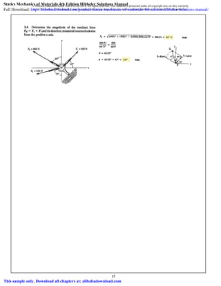
4. 2–4.
Determine the magnitude of the resultant force
and its direction, measured clockwise from the positive u axis.
FR = F1 + F2
SOLUTION
Ans.
Ans.f = 55.40° + 30° = 85.4°
u = 55.40°
605.1
sin 95°
=
500
sin u
FR = 2(300)2
+ (500)2
- 2(300)(500) cos 95° = 605.1 = 605 N
u
v
70
30
45
F1 300 N
F2 500 N
20
© Pearson Education South Asia Pte Ltd 2014. All rights reserved. This material is protected under all copyright laws as they currently
exist. No portion of this material may be reproduced, in any form or by any means, without permission in writing from the publisher.
5. 2–5.
SOLUTION
Ans.
Ans.F1v = 160 N
F1v
sin 30°
=
300
sin 110°
F1u = 205 N
F1u
sin 40°
=
300
sin 110°
Resolve the force into components acting along the u and
v axes and determine the magnitudes of the components.
F1
u
v
70
30
45
F1 300 N
F2 500 N
21
© Pearson Education South Asia Pte Ltd 2014. All rights reserved. This material is protected under all copyright laws as they currently
exist. No portion of this material may be reproduced, in any form or by any means, without permission in writing from the publisher.
6. 2–6.
Resolve the force into components acting along the u and
v axes and determine the magnitudes of the components.
F2
SOLUTION
Ans.
Ans.F2v = 482 N
F2v
sin 65°
=
500
sin 70°
F2u = 376 N
F2u
sin 45°
=
500
sin 70°
u
v
70Њ
30Њ
45Њ
F1 ϭ 300 N
F2 ϭ 500 N
22
© Pearson Education South Asia Pte Ltd 2014. All rights reserved. This material is protected under all copyright laws as they currently
exist. No portion of this material may be reproduced, in any form or by any means, without permission in writing from the publisher.
7. 2–7. If and the resultant force acts along the
positive u axis, determine the magnitude of the resultant
force and the angle .u
FB = 2 kN y
x
u
B
FA ϭ 3 kN
FB
A
u 30Њ
23
© Pearson Education South Asia Pte Ltd 2014. All rights reserved. This material is protected under all copyright laws as they currently
exist. No portion of this material may be reproduced, in any form or by any means, without permission in writing from the publisher.
8. 2–8. If the resultant force is required to act along the
positive u axis and have a magnitude of 5 kN, determine the
required magnitude of FB and its direction .u
y
x
u
B
FA ϭ 3 kN
FB
A
u 30Њ
24
© Pearson Education South Asia Pte Ltd 2014. All rights reserved. This material is protected under all copyright laws as they currently
exist. No portion of this material may be reproduced, in any form or by any means, without permission in writing from the publisher.
9. 2–9.
Resolve F1 into components along the u and axes and
determine the magnitudes of these components.
v
SOLUTION
Sine law:
Ans.
Ans.
F1u
sin 45°
=
250
sin 105°
F1u = 183 N
F1v
sin 30°
=
250
sin 105°
F1v = 129 N
F1 250 N
F2 150 N u
v
30
30
105
25
© Pearson Education South Asia Pte Ltd 2014. All rights reserved. This material is protected under all copyright laws as they currently
exist. No portion of this material may be reproduced, in any form or by any means, without permission in writing from the publisher.
10. 2–10.
SOLUTION
Sine law:
Ans.
Ans.
F2u
sin 75°
=
150
sin 75°
F2u = 150 N
F2v
sin 30°
=
150
sin 75°
F2v = 77.6 N
Resolve F2 into components along the u and axes and
determine the magnitudes of these components.
v
F1 250 N
F2 150 N u
v
30
30
105
26
© Pearson Education South Asia Pte Ltd 2014. All rights reserved. This material is protected under all copyright laws as they currently
exist. No portion of this material may be reproduced, in any form or by any means, without permission in writing from the publisher.
11. .
.
27
© Pearson Education South Asia Pte Ltd 2014. All rights reserved. This material is protected under all copyright laws as they currently
exist. No portion of this material may be reproduced, in any form or by any means, without permission in writing from the publisher.
12. .
.
.
28
© Pearson Education South Asia Pte Ltd 2014. All rights reserved. This material is protected under all copyright laws as they currently
exist. No portion of this material may be reproduced, in any form or by any means, without permission in writing from the publisher.
13. x
x¿
2–1 . The device is used for surgical replacement of the
knee joint. If the force acting along the leg is 360 N,
determine its components along the x and y axes.¿
60Њ
360 N
10Њ
y
x
y¿
x¿
3
.
.
29
© Pearson Education South Asia Pte Ltd 2014. All rights reserved. This material is protected under all copyright laws as they currently
exist. No portion of this material may be reproduced, in any form or by any means, without permission in writing from the publisher.
14. 2–1 . The device is used for surgical replacement of the
knee joint. If the force acting along the leg is 360 N,
determine its components along the x and y axes.¿
60Њ
360 N
10Њ
y
x
y¿
x¿
4
.
.
30
© Pearson Education South Asia Pte Ltd 2014. All rights reserved. This material is protected under all copyright laws as they currently
exist. No portion of this material may be reproduced, in any form or by any means, without permission in writing from the publisher.
15. 2–15.
SOLUTION
Parallelogram Law: The parallelogram law of addition is shown in Fig. a.
Trigonometry: Using law of cosines (Fig. b), we have
Ans.
The angle can be determined using law of sines (Fig. b).
Thus, the direction of FR measured from the x axis is
Ans.f = 33.16° - 30° = 3.16°
f
u = 33.16°
sin u = 0.5470
sin u
6
=
sin 100°
10.80
u
= 10.80 kN = 10.8 kN
FR = 282
+ 62
- 2(8)(6) cos 100°
The plate is subjected to the two forces at A and B as
shown. If , determine the magnitude of the resultant
of these two forces and its direction measured clockwise
from the horizontal.
u = 60°
A
B
FA 8 kN
FB 6 kN
40
u
31
© Pearson Education South Asia Pte Ltd 2014. All rights reserved. This material is protected under all copyright laws as they currently
exist. No portion of this material may be reproduced, in any form or by any means, without permission in writing from the publisher.
16. 2–16.
Determine the angle of for connecting member A to the
plate so that the resultant force of FA and FB is directed
horizontally to the right. Also, what is the magnitude of the
resultant force?
u
SOLUTION
Parallelogram Law: The parallelogram law of addition is shown in Fig. a.
Trigonometry: Using law of sines (Fig .b), we have
Ans.
From the triangle, . Thus, using law of
cosines, the magnitude of FR is
Ans.= 10.4 kN
FR = 282
+ 62
- 2(8)(6) cos 94.93°
f = 180° - (90° - 54.93°) - 50° = 94.93°
u = 54.93° = 54.9°
sin (90° - u) = 0.5745
sin (90° - u)
6
=
sin 50°
8
A
B
FA 8 kN
FB 6 kN
40
u
32
© Pearson Education South Asia Pte Ltd 2014. All rights reserved. This material is protected under all copyright laws as they currently
exist. No portion of this material may be reproduced, in any form or by any means, without permission in writing from the publisher.
17. .
.
33
© Pearson Education South Asia Pte Ltd 2014. All rights reserved. This material is protected under all copyright laws as they currently
exist. No portion of this material may be reproduced, in any form or by any means, without permission in writing from the publisher.
18. .
.
.
34
© Pearson Education South Asia Pte Ltd 2014. All rights reserved. This material is protected under all copyright laws as they currently
exist. No portion of this material may be reproduced, in any form or by any means, without permission in writing from the publisher.
19. 2–19.
SOLUTION
Ans.
Ans.
19.18
sin 1.47°
=
30.85
sin u
; u = 2.37°
FR = 2(30.85)2
+ (50)2
- 2(30.85)(50) cos 1.47° = 19.18 = 19.2 N
30.85
sin 73.13°
=
30
sin (70° - u¿
)
; u¿
= 1.47°
F¿
= 2(20)2
+ (30)2
- 2(20)(30) cos 73.13° = 30.85 N
Determine the magnitude and direction of the resultant
of the three forces by first finding the
resultant and then forming FR = F¿ + F3.F¿ = F1 + F2
FR = F1 + F2 + F3
y
x
F2 20 N
F1 30 N
20
3
5
4 F3 50 N
35
© Pearson Education South Asia Pte Ltd 2014. All rights reserved. This material is protected under all copyright laws as they currently
exist. No portion of this material may be reproduced, in any form or by any means, without permission in writing from the publisher.
20. 2–20.
Determine the magnitude and direction of the resultant
of the three forces by first finding the
resultant and then forming FR = F¿ + F1.F¿ = F2 + F3
FR = F1 + F2 + F3
SOLUTION
Ans.
Ans.u = 23.53° - 21.15° = 2.37°
19.18
sin 13.34°
=
30
sin f
; f = 21.15°
FR = 2(47.07)2
+ (30)2
- 2(47.07)(30) cos 13.34° = 19.18 = 19.2 N
20
sin u¿
=
47.07
sin 70°
; u¿
= 23.53°
F¿
= 2(20)2
+ (50)2
- 2(20)(50) cos 70° = 47.07 N
y
x
F2 20 N
F1 30 N
20
3
5
4 F3 50 N
36
© Pearson Education South Asia Pte Ltd 2014. All rights reserved. This material is protected under all copyright laws as they currently
exist. No portion of this material may be reproduced, in any form or by any means, without permission in writing from the publisher.
21. 2–21.
Two forces act on the screw eye. If and
, determine the angle
between them, so that the resultant force has a magnitude
of .FR = 800 N
u(0° … u … 180°)F2 = 600 N
F1 = 400 N
SOLUTION
The parallelogram law of addition and triangular rule are shown in Figs. a and b,
respectively.Applying law of cosines to Fig. b,
Ans.u = 75.52° = 75.5°
180° - u = 104.48
cos (180° - u) = - 0.25
8002
= 4002
+ 6002
- 480000 cos (180° - u)
800 = 24002
+ 6002
- 2(400)(600) cos (180° - u°)
F2
F1
u
37
© Pearson Education South Asia Pte Ltd 2014. All rights reserved. This material is protected under all copyright laws as they currently
exist. No portion of this material may be reproduced, in any form or by any means, without permission in writing from the publisher.
22. 2–22.
SOLUTION
Ans.
Since
Since
Then
Ans.FR = 2F cosa
u
2
b
cos a
u
2
b =
A
1 + cos u
2
FR = FA 22B 21 + cos u
cos (180° - u) = -cos u
FR = 2(F)2
+ (F)2
- 2(F)(F) cos (180° - u)
f =
u
2
u - f = f
sin (u - f) = sin f
F
sin f
=
F
sin (u - f)
Two forces F1 and F2 act on the screw eye. If their lines of
action are at an angle apart and the magnitude of each
force is determine the magnitude of the
resultant force FR and the angle between FR and F1.
F1 = F2 = F,
u
F2
F1
u
38
© Pearson Education South Asia Pte Ltd 2014. All rights reserved. This material is protected under all copyright laws as they currently
exist. No portion of this material may be reproduced, in any form or by any means, without permission in writing from the publisher.
23. 2–23.
Two forces act on the screw eye. If , determine
the magnitude of the resultant force and the angle if the
resultant force is directed vertically upward.
u
F = 600 N
SOLUTION
The parallelogram law of addition and triangular rule are shown in Figs. a and b
respectively.Applying law of sines to Fig. b,
Ans.
Using the result of ,
Again, applying law of sines using the result of ,
Ans.
FR
sin 113.13°
=
500
sin 30°
; FR = 919.61 N = 920 N
f
f = 180° - 30° - 36.87° = 113.13°
u
sin u
600
=
sin 30°
500
; sin u = 0.6 u = 36.87° = 36.9°
u
F
30Њ
500 N
y
x
39
© Pearson Education South Asia Pte Ltd 2014. All rights reserved. This material is protected under all copyright laws as they currently
exist. No portion of this material may be reproduced, in any form or by any means, without permission in writing from the publisher.
24. 2–24.
Two forces are applied at the end of a screw eye in order to
remove the post. Determine the angle
and the magnitude of force F so that the resultant force
acting on the post is directed vertically upward and has a
magnitude of 750 N.
u 10° … u … 90°2
SOLUTION
Parallelogram Law: The parallelogram law of addition is shown in Fig. a.
Trigonometry: Using law of sines (Fig. b), we have
Thus,
Ans.
Ans.F = 319 N
F
sin 18.59°
=
500
sin 30°
u = 180° - 30° - 131.41° = 18.59° = 18.6°
f = 131.41° 1By observation, f 7 90°2
sin f = 0.750
sin f
750
=
sin 30°
500
θ
F
30°
500 N
y
x
40
© Pearson Education South Asia Pte Ltd 2014. All rights reserved. This material is protected under all copyright laws as they currently
exist. No portion of this material may be reproduced, in any form or by any means, without permission in writing from the publisher.
25. 2-
Determine the magnitude and direction of the resultant force F1 . Express the result in terms of
the magnitudes of the component and resultantF2
and the angle .
Solution:
F
2
F
2
F2
2
2F F cos 29. 25
FR T
1 R R 2 T
1 R R 2 T
.
Ans.
41
© Pearson Education South Asia Pte Ltd 2014. All rights reserved. This material is protected under all copyright laws as they currently
exist. No portion of this material may be reproduced, in any form or by any means, without permission in writing from the publisher.
30. 2–26.
The beam is to be hoisted using two chains. Determine the
magnitudes of forces FA and FB acting on each chain in order
to develop a resultant force of 600 N directed along the
positive y axis. Set .u = 45°
SOLUTION
Ans.
Ans.
FB
sin 30°
=
600
sin 105°
; FB = 311 N
FA
sin 45°
=
600
sin 105°
; FA = 439 N
FB FA
y
x
30
u
42
© Pearson Education South Asia Pte Ltd 2014. All rights reserved. This material is protected under all copyright laws as they currently
exist. No portion of this material may be reproduced, in any form or by any means, without permission in writing from the publisher.
31. 2–27.
SOLUTION
For minimum FB, require
Ans.
Ans.
Ans.FB = 600 sin 30° = 300 N
FA = 600 cos 30° = 520 N
u = 60°
The beam is to be hoisted using two chains. If the resultant
force is to be 600 N directed along the positive y axis,
determine the magnitudes of forces FA and FB acting on
each chain and the angle of FB so that the magnitude of FB
is a minimum. FA acts at 30° from the y axis, as shown.
u
FB FA
y
x
30
u
43
© Pearson Education South Asia Pte Ltd 2014. All rights reserved. This material is protected under all copyright laws as they currently
exist. No portion of this material may be reproduced, in any form or by any means, without permission in writing from the publisher.
32. 2–28.
If the resultant force of the two tugboats is , directed
along the positive axis, determine the required magnitude
of force and its direction .uFB
x
3 kN
SOLUTION
The parallelogram law of addition and the triangular rule are shown in Figs. a and b,
respectively.
Applying the law of cosines to Fig. b,
Ans.
Using this result and applying the law of sines to Fig. b, yields
Ans.
sin u
2
=
sin 30°
1.615
u = 38.3°
= 1.615kN = 1.61 kN
FB = 222
+ 32
- 2(2)(3)cos 30°
x
y
A
B
FB
FA ϭ 2 kN
30Њ
C
u
44
© Pearson Education South Asia Pte Ltd 2014. All rights reserved. This material is protected under all copyright laws as they currently
exist. No portion of this material may be reproduced, in any form or by any means, without permission in writing from the publisher.
33. 2–29.
If and , determine the magnitude of the
resultant force of the two tugboats and its direction
measured clockwise from the positive axis.x
u = 45°FB = 3 kN
SOLUTION
The parallelogram law of addition and the triangular rule are shown in Figs. a and b,
respectively.
Applying the law of cosines to Fig. b,
Ans.
Using this result and applying the law of sines to Fig. b, yields
Thus, the direction angle of , measured clockwise from the positive axis, is
Ans.f = a - 30° = 46.22° - 30° = 16.2°
xFRf
sin a
3
=
sin 105°
4.013
a = 46.22°
= 4.013 kN = 4.01 kN
FR = 222
+ 32
- 2(2)(3) cos 105°
x
y
A
B
FB
FA ϭ 2 kN
30Њ
C
u
45
© Pearson Education South Asia Pte Ltd 2014. All rights reserved. This material is protected under all copyright laws as they currently
exist. No portion of this material may be reproduced, in any form or by any means, without permission in writing from the publisher.
34. 2–30.
If the resultant force of the two tugboats is required to be
directed towards the positive axis, and is to be a
minimum, determine the magnitude of and and the
angle .u
FBFR
FBx
SOLUTION
For to be minimum, it has to be directed perpendicular to .Thus,
Ans.
The parallelogram law of addition and triangular rule are shown in Figs. a and b,
respectively.
By applying simple trigonometry to Fig. b,
Ans.
Ans.FR = 2 cos 30° = 1.73 kN
FB = 2 sin 30° = 1 kN
u = 90°
FRFB
x
y
A
B
FB
FA ϭ 2 kN
30Њ
C
u
46
© Pearson Education South Asia Pte Ltd 2014. All rights reserved. This material is protected under all copyright laws as they currently
exist. No portion of this material may be reproduced, in any form or by any means, without permission in writing from the publisher.
35. 2-
If the tension in the cable is F1, determine the magnitude and direction of the resultant force acting
on the pulley. This angle defines the same angle T of line AB on the tailboard block.
Given:
F1 400 N
T1 30 deg
Solution:
FR F1
2
F1
2
2F1 F1 cos 90 deg T1 39. §
¨
©
·
¸
¹
T 60deg
31.
Ans.
Ans.
47
© Pearson Education South Asia Pte Ltd 2014. All rights reserved. This material is protected under all copyright laws as they currently
exist. No portion of this material may be reproduced, in any form or by any means, without permission in writing from the publisher.
40. 2-32
Determine the magnitude of the resultant force and its direction, measured clockwise from
the positive x axis.
Given:
F1 70 N
F2 50 N
F3 65 N
T 30 deg
I 45 deg
Solution:
o FRx = 6Fx; FRX F1 F2 cos T 44. FR FRX
2
FRY
2
T atan
FRY
FRX
§
¨
©
·
¸
¹
FR 97.8 N
T 46.5 deg
.
Ans.
Ans.
48
© Pearson Education South Asia Pte Ltd 2014. All rights reserved. This material is protected under all copyright laws as they currently
exist. No portion of this material may be reproduced, in any form or by any means, without permission in writing from the publisher.
45. 2–33.
Determine the magnitude of the resultant force and its
direction, measured counterclockwise from the positive x axis.
SOLUTION
Ans.
Ans.u = 180° + 72.64° = 253°
f = tan-1
B
-520.9
-162.8
R = 72.64°
FR = 2 (-162.8)2
+ (-520.9)2
= 546 N
+ cFRy
= ©Fy ; FRy = -
3
5
(850) - 625 cos 30° + 750 cos 45° = -520.9 N
:+ FRx
= ©Fx ; FRx
=
4
5
(850) - 625 sin 30° - 750 sin 45° = -162.8 N 30
x
y
3
4
5
45
F3 750 N
F2 625 N F1 850 N
49
© Pearson Education South Asia Pte Ltd 2014. All rights reserved. This material is protected under all copyright laws as they currently
exist. No portion of this material may be reproduced, in any form or by any means, without permission in writing from the publisher.
46. 2–34.
Resolve and into their and components.yxF2F1
SOLUTION
Ans.
Ans.= {177i 177j} N
F2 = {250 cos 45°(+i)+250 sin 45°(-j)} N
= {200i+346j} N
F1 = {400 sin 30°(+i)+400 cos 30°(+j)} N
F1 ϭ 400 N
F2 ϭ 250 N
x
y
60Њ
30Њ
45Њ
-
50
© Pearson Education South Asia Pte Ltd 2014. All rights reserved. This material is protected under all copyright laws as they currently
exist. No portion of this material may be reproduced, in any form or by any means, without permission in writing from the publisher.
47. 2–35.
Determine the magnitude of the resultant force and its
direction measured counterclockwise from the positive x axis.
SOLUTION
Rectangular Components: By referring to Fig. a, the x and y components of and
can be written as
Resultant Force: Summing the force components algebraically along the and
axes, we have
The magnitude of the resultant force is
Ans.
The direction angle of , Fig. b, measured counterclockwise from the positive
axis, is
Ans.u = tan-1
c
(FR)y
(FR)x
d = tan-1
a
169.63
376.78
b = 24.2°
FRu
FR = 2(FR)x
2
+ (FR)y
2
= 2376.782
+ 169.632
= 413 N
FR
(FR)y = 346.41 - 176.78 = 169.63 N c+ c©(FR)y = ©Fy;
(FR)x = 200 + 176.78 = 376.78 N+
: ©(FR)x = ©Fx;
y
x
(F2)y = 250 sin 45° = 176.78 N(F2)x = 250 cos 45° = 176.78 N
(F1)y = 400 cos 30° = 346.41 N(F1)x = 400 sin 30° = 200 N
F2
F1
F1 ϭ 400 N
F2 ϭ 250 N
x
y
60Њ
30Њ
45Њ
51
© Pearson Education South Asia Pte Ltd 2014. All rights reserved. This material is protected under all copyright laws as they currently
exist. No portion of this material may be reproduced, in any form or by any means, without permission in writing from the publisher.
48. 2–36.
Resolve each force acting on the gusset plate into its and
components, and express each force as a Cartesian vector.y
x
Ans.
Ans.
Ans.= {520 i - 390j)} N
F3 = e650a
4
5
b(+i) + 650 a
3
5
b(-j)f N
= {530i + 530j} N
F2 = {750 cos 45°(+i) + 750 sin 45°(+j)} N
F1 = {900(+i)} = {900i} N
F1 ϭ 900 N
F2 ϭ 750 N
45Њ
F3 ϭ 650 N
3
4
5
x
y
52
© Pearson Education South Asia Pte Ltd 2014. All rights reserved. This material is protected under all copyright laws as they currently
exist. No portion of this material may be reproduced, in any form or by any means, without permission in writing from the publisher.
49. 2–37.
Determine the magnitude of the resultant force acting on
the plate and its direction, measured counterclockwise from
the positive x axis.
SOLUTION
Rectangular Components: By referring to Fig. a, the x and y components of , ,
and can be written as
Resultant Force: Summing the force components algebraically along the and
axes, we have
The magnitude of the resultant force is
Ans.
The direction angle of , measured clockwise from the positive axis, is
Ans.u = tan-1
c
(FR)y
(FR)x
d = tan-1
a
140.33
1950.33
b = 4.12°
xFRu
FR = 2(FR)x
2
+ (FR)y
2
= 21950.332
+ 140.332
= 1955 N = 1.96 kN
FR
(FR)y = 530.33 - 390 = 140.33 N c+ c©(FR)y = ©Fy;
(FR)x = 900 + 530.33 + 520 = 1950.33 N :+
: ©(FR)x = ©Fx;
y
x
(F3)y = 650a
3
5
b = 390 N(F3)x = 650a
4
5
b = 520 N
(F2)y = 750 sin 45° = 530.33 N(F2)x = 750 cos 45° = 530.33 N
(F1)y = 0(F1)x = 900 N
F3
F2F1
F1 ϭ 900 N
F2 ϭ 750 N
45Њ
F3 ϭ 650 N
3
4
5
x
y
53
© Pearson Education South Asia Pte Ltd 2014. All rights reserved. This material is protected under all copyright laws as they currently
exist. No portion of this material may be reproduced, in any form or by any means, without permission in writing from the publisher.
50. .
54
© Pearson Education South Asia Pte Ltd 2014. All rights reserved. This material is protected under all copyright laws as they currently
exist. No portion of this material may be reproduced, in any form or by any means, without permission in writing from the publisher.
51. 2–39.
Resolve each force acting on the support into its x and
y components, and express each force as a Cartesian vector.
SOLUTION
Ans.
Ans.
Ans.
= {600i - 250j} N
F3 = e650a
12
13
b(+i) + 650a
5
13
b(-j)f N
= {-424i + 424j} N
F2 = {600 sin 45°(-i) + 600 cos 45°(+j)} N
= {400i + 693j} N
F1 = {800 cos 60°(+i) + 800 sin 60°(+j)} N
F1 ϭ 800 NF2 ϭ 600 N
45Њ
60Њ
F3 ϭ 650 N
5
12
13
x
y
55
© Pearson Education South Asia Pte Ltd 2014. All rights reserved. This material is protected under all copyright laws as they currently
exist. No portion of this material may be reproduced, in any form or by any means, without permission in writing from the publisher.
52. 2–40.
Determine the magnitude of the resultant force and its
direction , measured counterclockwise from the positive
axis.x
u
SOLUTION
Rectangular Components: By referring to Fig. a, the x and y components of , ,
and can be written as
Resultant Force: Summing the force components algebraically along the and
axes, we have
The magnitude of the resultant force is
Ans.
The direction angle of , Fig. b, measured counterclockwise from the positive
axis, is
Ans.u = tan-1
c
(FR)y
(FR)x
d = tan-1
a
867.08
575.74
b = 56.4°
x
FRu
FR = 2(FR)x
2
+ (FR)y
2
= 2575.742
+ 867.082
= 1041 N = 1.04 kN
FR
(FR)y = - 692.82 + 424.26 - 250 = 867.08 N c+ c©(FR)y = ©Fy;
(FR)x = 400 - 424.26 + 600 = 575.74 N :+
: ©(FR)x = ©Fx;
y
x
(F3)y = 650 a
5
13
b = 250 N(F3)x = 650a
12
13
b = 600 N
(F2)y = 600 cos 45° = 424.26 N(F2)x = 600 sin 45° = 424.26 N
(F1)y = 800 sin 60° = 692.82 N(F1)x = 800 cos 60° = 400 N
F3
F2F1
F1 ϭ 800 NF2 ϭ 600 N
45Њ
60Њ
F3 ϭ 650 N
5
12
13
x
y
56
© Pearson Education South Asia Pte Ltd 2014. All rights reserved. This material is protected under all copyright laws as they currently
exist. No portion of this material may be reproduced, in any form or by any means, without permission in writing from the publisher.
53. 2-
Determine the magnitude of the resultant force and its direction, measured counterclockwise
from the positive x axis.
Units Used:
kN 10
3
N
Given:
F1 30 kN
F2 26 kN
T 30 deg
c 5
d 12
Solution:
o FRx = 6Fx;
FRx F1 sin T 55. d
c
2
d
2
§
¨
©
·
¸
¹
F2 FRy 2 kN
FR FRx
2
FRy
2
FR 25.1 kN
I atan
FRy
FRx
§
¨
©
·
¸
¹
I 4.5 deg
E 180 deg I E 184.5 deg
41.
Ans.
Ans.
57
© Pearson Education South Asia Pte Ltd 2014. All rights reserved. This material is protected under all copyright laws as they currently
exist. No portion of this material may be reproduced, in any form or by any means, without permission in writing from the publisher.
56. 2–42.
Determine the magnitude and orientation of so that
the resultant force is directed along the positive y axis and
has a magnitude of 1500 N.
FBu
SOLUTION
Scalar Notation: Summing the force components algebraically, we have
(1)
(2)
Solving Eq. (1) and (2) yields
Ans.u = 68.6° FB = 960 N
FB sin u = 893.8
1500 = 700 cos 30° + FB sin u+ c FRy
= ©Fy;
FB cos u = 350
0 = 700 sin 30° - FB cos u:+ FRx
= ©Fx;
BF
AF = 700 N
x
y
B A
θ
30°
58
© Pearson Education South Asia Pte Ltd 2014. All rights reserved. This material is protected under all copyright laws as they currently
exist. No portion of this material may be reproduced, in any form or by any means, without permission in writing from the publisher.
57. 2–43.
SOLUTION
Scalar Notation: Summing the force components algebraically, we have
The magnitude of the resultant force is
Ans.
The direction angle u measured counterclockwise from the positive y axis is
Ans.u = tan-1
FRx
FRy
= tan-1
¢
213.8
811.4
≤ = 14.8°
FR = 2F2
Rx
+ F2
Ry
= 2213.82
+ 811.42
= 839 N
FR
= 811.4 N c
+ cFRy
= ©Fy ; FRy
= 700 cos 30° + 600 sin 20°
= -213.8 N = 213.8 N ;
:+ FRx
= ©Fx ; FRx
= 700 sin 30° - 600 cos 20°
Determine the magnitude and orientation, measured
counterclockwise from the positive y axis, of the resultant
force acting on the bracket, if and u = 20°.FB = 600 N
FA 700 N
x
y
B A
30
FB
u
59
© Pearson Education South Asia Pte Ltd 2014. All rights reserved. This material is protected under all copyright laws as they currently
exist. No portion of this material may be reproduced, in any form or by any means, without permission in writing from the publisher.
58. 2–44.
The magnitude of the resultant force acting on the bracket
is to be 400 N. Determine the magnitude of if .f = 30°F1
SOLUTION
Rectangular Components: By referring to Fig. a, the x and y components of , ,
and can be written as
Resultant Force: Summing the force components algebraically along the and
axes, we have
Since the magnitude of the resultant force is , we can write
Ans.
Solving,
or Ans.
The negative sign indicates that must act in the opposite sense to that
shown in the figure.
F1 = 417 N
F1 = -417 NF1 = 314 N
F1
2
+ 103.32F1 - 130967.17 = 0
400 = 2(0.8660F1 - 36.45)2
+ (0.5F1 + 166.45)2
FR = 2(FR)x
2
+ (FR)y
2
FR = 400 N
= 0.5F1 + 166.45
(FR)y = 0.5F1 + 520 - 353.55+ c©(FR)y = ©Fy;
= 0.8660F1 - 36.45
(FR)x = 0.8660F1 - 390 + 353.55+
: ©(FR)x = ©Fx;
y
x
(F3)y = 500 sin 45° = 353.55 N(F3)x = 500 cos 45° = 353.55 N
(F2)y = 650 a
4
5
b = 520 N(F2)x = 650a
3
5
b = 390 N
(F1)y = F1 sin 30° = 0.5F1(F1)x = F1 cos 30° = 0.8660F1
F3
F2F1
3
4 5
u
y
x
45Њ
45Њ
F3 ϭ 500 N
F2 ϭ 650 N
F1
f
60
© Pearson Education South Asia Pte Ltd 2014. All rights reserved. This material is protected under all copyright laws as they currently
exist. No portion of this material may be reproduced, in any form or by any means, without permission in writing from the publisher.
59. 3
4 5
u
y
x
45Њ
45Њ
F3 ϭ 500 N
F2 ϭ 650 N
F1
f
2–45.
If the resultant force acting on the bracket is to be directed
along the positive u axis, and the magnitude of is
required to be minimum, determine the magnitudes of the
resultant force and .F1
F1
SOLUTION
Rectangular Components: By referring to Figs. a and b, the x and y components of
, , , and can be written as
Resultant Force: Summing the force components algebraically along the and
axes, we have
(1)
(2)
Eliminating from Eqs. (1) and (2), yields
(3)
The first derivative of Eq. (3) is
(4)
The second derivative of Eq. (3) is
(5)
For to be minimum, . Thus, from Eq. (4)
Substituting into Eq. (5), yields
This shows that indeed produces minimum .Thus, from Eq. (3)
Ans.
Substituting and into either Eq. (1) or Eq. (2), yields
Ans.FR = 91 9 N
F1 = 143.47 Nf = -45°
F1 =
202.89
cos (-45°) - sin (-45°)
= 143.47 N = 143 N
F1f = -45°
d2
F1
df2
= 0.7071 0
f = -45°
f = -45°
tan f = -1
sin f + cos f = 0
dF1
df
= 0F1
d2
F1
df2
=
2(sin f + cos f)2
(cos f - sin f)3
+
1
cos f - sin f
dF1
df
=
sin f + cos f
(cos f - sin f)2
F1 =
202.89
cos f - sin f
FR
0.7071FR = F1 sin f + 520 - 353.55+ c©(FR)y = ©Fy;
0.7071FR = F1 cos f - 390 + 353.55+
: ©(FR)x = ©Fx;
y
x
(FR)y = FR sin 45° = 0.7071FR(FR)x = FR cos 45° = 0.7071FR
(F3)y = 500 sin 45° = 353.55 N(F3)x = 500 cos 45° = 353.55 N
(F2)y = 650 a
4
5
b = 520 N(F2)x = 650a
3
5
b = 390 N
(F1)y = F1 sin f(F1)x = F1 cos f
FRF3F2F1
.
61
© Pearson Education South Asia Pte Ltd 2014. All rights reserved. This material is protected under all copyright laws as they currently
exist. No portion of this material may be reproduced, in any form or by any means, without permission in writing from the publisher.
60. 2–46.
If the magnitude of the resultant force acting on the bracket
is 600 N, directed along the positive axis, determine the
magnitude of and its direction .fF
u
SOLUTION
Rectangular Components: By referring to Figs. a and b, the x and y components of
, , , and can be written as
Resultant Force: Summing the force components algebraically along the and
axes, we have
(1)
(2)
Solving Eqs. (1) and (2), yields
Ans.F1 = 528 Nf = 29.2°
F1 sin f = 257.82
424.26 = F1 sin f + 520 - 353.55+ c©(FR)y = ©Fy;
F1 cos f = 460.71
424.26 = F1 cos f - 390 + 353.55+
: ©(FR)x = ©Fx;
y
x
(FR)y = 600 sin 45° = 424.26 N(FR)x = 600 cos 45° = 424.26 N
(F3)y = 500 cos 45° = 353.55 N(F3)x = 500 cos 45° = 353.55 N
(F2)y = 650 a
4
5
b = 520 N(F2)x = 650a
3
5
b = 390 N
(F1)y = F1 sin f(F1)x = F1 cos f
FRF3F2F1
3
4 5
u
y
x
45Њ
45Њ
F3 ϭ 500 N
F2 ϭ 650 N
F1
f
62
© Pearson Education South Asia Pte Ltd 2014. All rights reserved. This material is protected under all copyright laws as they currently
exist. No portion of this material may be reproduced, in any form or by any means, without permission in writing from the publisher.
61. 2–47.
SOLUTION
Since ,
Ans.
From the figure,
tan u =
F1 sin f
Ans.
F2 + F1 cos f
tanu =
F1 sin f
F2 + F1 cos f
FR = 2F2
1 + F2
2 + 2F1F2 cos f
cos (180° - f) = -cos f
F2
R = F2
1 + F2
2 - 2F1F2 cos (180° - f)
Determine the magnitude and direction u of the resultant
force Express the result in terms of the magnitudes of
the components and and the angle f.F2F1
FR.
F1 FR
F2
u
f
–1
≤¢
63
© Pearson Education South Asia Pte Ltd 2014. All rights reserved. This material is protected under all copyright laws as they currently
exist. No portion of this material may be reproduced, in any form or by any means, without permission in writing from the publisher.
62. 2–48.
SOLUTION
Rectangular Components: By referring to Fig. a, the x and y components of each
force can be written as
Resultant Force: Summing the force components algebraically along the x and y axes,
The magnitude of the resultant force FR is
Ans.
The direction angle of FR, Fig. b, measured clockwise from the x axis, is
Ans.u = tan-1
B
(FR)y
(FR)x
R = tan-1
¢
493.01
499.62
≤ = 44.6°
u
FR = 2(FR)x
2
+ (FR)y
2
= 2499.622
+ 493.012
= 701.91 N = 702 N
+ c©(FR)y = ©Fy ; (FR)y = 300 - 433.01 - 360 = -493.01 N = 493.01 N T
:+ ©(FR)x = ©Fx ; (FR)x = 519.62 + 250 - 270 = 499.62 N :
(F3)x = 450a
3
5
b = 270 N (F3)y = 450a
4
5
b = 360 N
(F2)x = 500 cos 60° = 250 N (F2)y = 500 sin 60° = 433.01 N
(F1)x = 600 cos 30° = 519.62 N (F1)y = 600 sin 30° = 300 N
If and , determine the magnitude of the
resultant force acting on the eyebolt and its direction
measured clockwise from the positive x axis.
f = 30°F1 = 600 N y
x
3
45
F2 500 N
F1
F3 450 N
f
60
64
© Pearson Education South Asia Pte Ltd 2014. All rights reserved. This material is protected under all copyright laws as they currently
exist. No portion of this material may be reproduced, in any form or by any means, without permission in writing from the publisher.
63. 2–49.
SOLUTION
Rectangular Components: By referring to Figs. a and b, the x and y components of
F1, F2, F3, and FR can be written as
Resultant Force: Summing the force components algebraically along the x and y axes,
(1)
(2)
Solving Eqs. (1) and (2), yields
Ans.f = 42.4° F1 = 731 N
F1 sin f = 493.01
+ c ©(FR)y = ©Fy ; -300 = F1 sin f - 433.01 - 360
F1 cos f = 539.62
:+ ©(FR)x = ©Fx ; 519.62 = F1 cos f + 250 - 270
(FR)y = 600 sin 30° = 300 N(FR)x = 600 cos 30° = 519.62 N
(F3)y = 450a
4
5
b = 360 N(F3)x = 450a
3
5
b = 270 N
(F2)y = 500 sin 60° = 433.01 N(F2)x = 500 cos 60° = 250 N
(F1)y = F1 sin f(F1)x = F1 cos f
If the magnitude of the resultant force acting on the
eyebolt is 600 N and its direction measured clockwise from
the positive x axis is , determine the magnitude of
F1 and the angle .f
u = 30°
y
x
3
45
F2 500 N
F1
F3 450 N
f
60
65
© Pearson Education South Asia Pte Ltd 2014. All rights reserved. This material is protected under all copyright laws as they currently
exist. No portion of this material may be reproduced, in any form or by any means, without permission in writing from the publisher.
64. 2–50.
SOLUTION
Scalar Notation: Summing the force components algebraically, we have
(1)
(2)
Solving Eqs. (1) and (2) yields
Ans.u = 29.1° F1 = 275 N
F1 cos u = 240
+ c FRy
= ©Fy ; FRy
= 800 = F1 cos u + 400 sin 30° + 600a
3
5
b
F1 sin u = 133.6
:+ FRx
= ©Fx ; FRx
= 0 = F1 sin u + 400 cos 30° - 600a
4
5
b
Determine the magnitude of F1 and its direction so that
the resultant force is directed vertically upward and has a
magnitude of 800 N.
u
A
x
y
F1
400 N
600 N
3
4
5
30
u
66
© Pearson Education South Asia Pte Ltd 2014. All rights reserved. This material is protected under all copyright laws as they currently
exist. No portion of this material may be reproduced, in any form or by any means, without permission in writing from the publisher.
65. 2–51.
Determine the magnitude and direction measured
counterclockwise from the positive x axis of the resultant
force of the three forces acting on the ring A. Take
and .u = 20°F1 = 500 N
SOLUTION
Scalar Notation: Summing the force components algebraically, we have
The magnitude of the resultant force FR is
Ans.
The direction angle measured counterclockwise from positive x axis is
Ans.u = tan-1
FRy
FRx
= tan-1
a
1029.8
37.42
b = 87.9°
u
FR = 2F2
Rx
+ F2
Ry
= 237.422
+ 1029.82
= 1030.5 N = 1.03 kN
= 1029.8 N c
+ cFRy
= ©Fy ; FRy
= 500 cos 20° + 400 sin 30° + 600a
3
5
b
= 37.42 N :
:+ FRx
= ©Fx ; FRx
= 500 sin 20° + 400 cos 30° - 600a
4
5
b
A
x
y
F1
400 N
600 N
3
4
5
30
u
67
© Pearson Education South Asia Pte Ltd 2014. All rights reserved. This material is protected under all copyright laws as they currently
exist. No portion of this material may be reproduced, in any form or by any means, without permission in writing from the publisher.
66. 2–52.
Determine the magnitude of force F so that the resultant
of the three forces is as small as possible. What is the
minimum magnitude of FR?
FR
SOLUTION
Scalar Notation: Summing the force components algebraically, we have
The magnitude of the resultant force is
(1)
(2)
(3)
In order to obtain the minimum resultant force , . From Eq. (2)
Ans.
Substituting into Eq. (1), we have
Ans.
Substituting with into Eq. (3), we have
Hence, is indeed producing a minimum resultant force.F = 5.96 kN
d2
FR
dF2
= 0.429 7 0
B(2.330)
d2
FR
dF2
+ 0R = 1
dFR
dF
= 0FR = 2.330 kN
= 2.330 kN = 2.33 kN
FR = 25.9642
- 11.93(5.964) + 41
F = 5.964 kN
F = 5.964 kN = 5.96 kN
2FR
dFR
dF
= 2F - 11.93 = 0
dFR
dF
= 0FR
¢FR
d2
FR
dF2
+
dFR
dF
*
dFR
dF
≤ = 1
2FR
dFR
dF
= 2F - 11.93
F2
R = F2
- 11.93F + 41
= 2F2
- 11.93F + 41
= 2(5 - 0.50F)2
+ (0.8660F - 4)2
FR = 2F2
Rx
+ F2
Ry
FR
= 0.8660F - 4 c
+ cFRy
= ©Fy ; FRy
= F cos 30° - 4
= 5 - 0.50F :
:+ FRx
= ©Fx ; FRx
= 5 - F sin 30° 4 kN
5 kN
F
30
68
© Pearson Education South Asia Pte Ltd 2014. All rights reserved. This material is protected under all copyright laws as they currently
exist. No portion of this material may be reproduced, in any form or by any means, without permission in writing from the publisher.
67. 2–53.
Determine the magnitude of force so that the resultant
force of the three forces is as small as possible. What is the
magnitude of the resultant force?
F
SOLUTION
;
;
(1)FR
2
= (-4.1244 - F cos 45°)2
+ (7 - F sin 45°)2
= 7 - F sin 45°
FRy = -F sin 45° + 14 sin 30°+ cFRy = ©Fy
= -4.1244 - F cos 45°
FRz = 8 - F cos 45° - 14 cos 30°+
: FRx = ©Fx
F
8 kN
14 kN
45Њ30Њ
Ans.
From Eq. (1); Ans.
Also, from the figure require
;
Ans.
;
Ans.FR = 7.87 kN
FR = 14 cos 15° - 8 sin 45°(FR)y¿ = ©Fy¿
F = 2.03 kN
F + 14 sin 15° - 8 cos 45° = 0(FR)x¿ = 0 = ©Fx¿
FR = 7.87 kN
F = 2.03 kN
2FR
dFR
dF
= 2(-4.1244 - F cos 45°)(- cos 45°) + 2(7 - F sin 45°)(-sin 45°) = 0
69
© Pearson Education South Asia Pte Ltd 2014. All rights reserved. This material is protected under all copyright laws as they currently
exist. No portion of this material may be reproduced, in any form or by any means, without permission in writing from the publisher.
68. 2–54.
SOLUTION
Ans.
Ans.F1 = 889 N
u + 30° = 66.97°, u = 37.0°
F1 cos(u + 30°) = 347.827
F1 sin(u + 30°) = 818.198
+ cFRy = ©Fy ; -1000 sin 30° = 450 sin 45° - F1 sin(u + 30°)
:+ FRx = ©Fx ; 1000 cos 30° = 200 + 450 cos 45° + F1 cos(u + 30°)
Three forces act on the bracket.Determine the magnitude and
direction of so that the resultant force is directed along the
positive axis and has a magnitude of 1 kN.x¿
F1u
F2 450 N
F1
F3 200 N
45
30
y
x
x¿
u
70
© Pearson Education South Asia Pte Ltd 2014. All rights reserved. This material is protected under all copyright laws as they currently
exist. No portion of this material may be reproduced, in any form or by any means, without permission in writing from the publisher.
69. 2–55.
If and determine the magnitude and
direction, measured counterclockwise from the axis, of
the resultant force of the three forces acting on the bracket.
x¿
u = 20°,F1 = 300 N
SOLUTION
Ans.
Ans.f = 37.1°
f (angle from x¿ axis) = 30° + 7.10°
f¿ = 7.10°
f¿ (angle from x axis) = tan-1
B
88.38
711.03
R
FR = 2 (711.03)2
+ (88.38)2
= 717 N
+ cFRy = ©Fy ; FRy = -300 sin 50° + 450 sin 45° = 88.38 N
:+ FRx = ©Fx ; FRx = 300 cos 50° + 200 + 450 cos 45° = 711.03 N
F2 ϭ 450 N
F1
F3 ϭ 200 N
45Њ
30Њ
y
x
x¿
u
71
© Pearson Education South Asia Pte Ltd 2014. All rights reserved. This material is protected under all copyright laws as they currently
exist. No portion of this material may be reproduced, in any form or by any means, without permission in writing from the publisher.
70. .
.
72
© Pearson Education South Asia Pte Ltd 2014. All rights reserved. This material is protected under all copyright laws as they currently
exist. No portion of this material may be reproduced, in any form or by any means, without permission in writing from the publisher.
71. .
.
73
© Pearson Education South Asia Pte Ltd 2014. All rights reserved. This material is protected under all copyright laws as they currently
exist. No portion of this material may be reproduced, in any form or by any means, without permission in writing from the publisher.
72. 2–58.
If the magnitude of the resultant force acting on the bracket
is to be 450 N directed along the positive u axis, determine
the magnitude of F1 and its direction .f
SOLUTION
Rectangular Components: By referring to Fig. a, the x and y components of F1, F2,
F3, and FR can be written as
Resultant Force:Summing the force components algebraically along the x and y axes,
(1)
(2)
Solving Eqs. (1) and (2), yields
Ans.f = 10.9° F1 = 474 N
F1 cosf = 465
+ c ©(FR)y = ©Fy; 225 = F1 cos f - 240
F1 sin f = 89.71
:+ ©(FR)x = ©Fx; 389.71 = F1 sin f + 200 + 100
(FR)x = 450 cos 30° = 389.71 N (FR)y = 450 sin 30° = 225 N
(F3)x = 260¢
5
13
≤ = 100 N (F3)y = 260¢
12
13
≤ = 240 N
(F2)x = 200 F2)y = 0
(F1)x = F1 sin f (F1)y = F1 cos f
5
12 13
y
x
u
F3 260 N
F2 200 N
F1
f
30
N (
74
© Pearson Education South Asia Pte Ltd 2014. All rights reserved. This material is protected under all copyright laws as they currently
exist. No portion of this material may be reproduced, in any form or by any means, without permission in writing from the publisher.
73. 2–59.
SOLUTION
Rectangular Components: By referring to Fig. a, the x and y components of F1, F2,
and F3 can be written as
Resultant Force: Summing the force components algebraically along the x and y axes,
The magnitude of the resultant force FR is
(1)
Thus,
(2)
The first derivative of Eq. (2) is
(3)2FR
dFR
dF1
= 2F1 - 115.69
FR
2
= F1
2
- 115.69F1 + 147 600
= 2F2
1 - 115.69F1 + 147 600
= 2(0.5F1 + 300)2
+ (0.8660F1 - 240)2
FR = 2(FR)x
2
+ (FR)y
2
+ c©(FR)y = ©Fy; (FR)y = 0.8660F1 - 240
:+ ©(FR)x = ©Fx; (FR)x = 0.5F1 + 200 + 100 = 0.5F1 + 300
(F3)x = 260a
5
13
b = 100 N (F3)y = 260a
12
13
b = 240 N
(F2)x = 200 N (F2)y = 0
(F1)x = F1 sin 30° = 0.5F1 (F1)y = F1 cos 30° = 0.8660F1
If the resultant force acting on the bracket is required to be
a minimum, determine the magnitudes of F1 and the
resultant force. Set .f = 30°
5
12 13
y
x
u
F3 260 N
F2 200 N
F1
f
30
For FR to be minimum, .Thus, from Eq. (3)
Ans.
Ans.F1 = 57.846 N = 57.8 N
2FR
dFR
dF1
= 2F1 - 115.69 = 0
dFR
dF1
= 0
FR = 2(57.846)2
- 115.69(57.846) + 147 600 = 380 N
from Eq. (1),
75
© Pearson Education South Asia Pte Ltd 2014. All rights reserved. This material is protected under all copyright laws as they currently
exist. No portion of this material may be reproduced, in any form or by any means, without permission in writing from the publisher.
74. 2–60.
The stock mounted on the lathe is subjected to a force of
. Determine the coordinate direction angle and
express the force as a Cartesian vector.
b60 N
SOLUTION
Use
Ans.
Ans.= {30i - 30j + 42.4k} N
F = 60 N(cos 60°i + cos 120°j + cos 45°k)
b = 120°
b = 60°, 120°
cos b = ; 0.5
1 = cos2
60° + cos2
b + cos2
45°
1 = 2cos2
a + cos2
b + cos2
g
x
z
y
45Њ
60 N
60Њ
b
76
© Pearson Education South Asia Pte Ltd 2014. All rights reserved. This material is protected under all copyright laws as they currently
exist. No portion of this material may be reproduced, in any form or by any means, without permission in writing from the publisher.
75. 2– . Determine the coordinate angle for F2 and then
express each force acting on the bracket as a Cartesian
vector.
g
y
z
F2 ϭ 600 N
F1 ϭ 450 N
45Њ
30Њ
45Њ
60Њ
x
61
77
© Pearson Education South Asia Pte Ltd 2014. All rights reserved. This material is protected under all copyright laws as they currently
exist. No portion of this material may be reproduced, in any form or by any means, without permission in writing from the publisher.
76. 2–6 . Determine the magnitude and coordinate direction
angles of the resultant force acting on the bracket.
y
z
F2 ϭ 600 N
F1 ϭ 450 N
45Њ
30Њ
45Њ
60Њ
x
2
78
© Pearson Education South Asia Pte Ltd 2014. All rights reserved. This material is protected under all copyright laws as they currently
exist. No portion of this material may be reproduced, in any form or by any means, without permission in writing from the publisher.
77. 2–63.
The bolt is subjected to the force F, which has components
acting along the x, y, z axes as shown. If the magnitude of F is
80 N, and and determine the magnitudes
of its components.
g = 45°,a = 60°
SOLUTION
Ans.
Ans.
Ans.Fz = |80 cos 45°| = 56.6 N
Fy = |80 cos 120°| = 40 N
Fx = |80 cos 60°| = 40 N
b = 120°
= 21 - cos2
60° - cos2
45°
cosb = 21 - cos2
a - cos2
g
x
z
Fz
Fy
Fx
F
y
a
b
g
79
© Pearson Education South Asia Pte Ltd 2014. All rights reserved. This material is protected under all copyright laws as they currently
exist. No portion of this material may be reproduced, in any form or by any means, without permission in writing from the publisher.
78. 2-
Determine the magnitude and coordinate direction angles of the force F acting on the stake.
Given:
Fh 40 N
T 70 deg
c 3
d 4
Solution:
F Fh
c
2
d
2
d
§
¨
©
·
¸
¹
F 50 N
Fx Fh cos T 80. Fz
c
c
2
d
2
§
¨
©
·
¸
¹
F
Fx 13.7 N Fy 37.6 N Fz 30 N
D acos
Fx
F
§
¨
©
·
¸
¹
E acos
Fy
F
§
¨
©
·
¸
¹
J acos
Fz
F
§
¨
©
·
¸
¹
D 74.1 deg E 41.3 deg J 53.1 deg
64.
Ans.
Ans.
80
© Pearson Education South Asia Pte Ltd 2014. All rights reserved. This material is protected under all copyright laws as they currently
exist. No portion of this material may be reproduced, in any form or by any means, without permission in writing from the publisher.
81. 2-
Determine the magnitude and coordinate direction angles of the force F acting on the stake.
Given:
Fh 40N:=
θ deg:=
c 3:=
d 4:=
Solution:
F Fh
c
2
d
2
+
d
⋅:=
F 50N=
Fx Fh cos θ( )⋅:= Fy Fh sin θ( )⋅:= Fz
c
c
2
d
2
+
F⋅:=
Fx N= Fy 30.6 N= Fz 30N=
α acos
Fx
F
⎛
⎜
⎝
⎞
⎟
⎠
:= β acos
Fy
F
⎛
⎜
⎝
⎞
⎟
⎠
:= γ acos
Fz
F
⎛
⎜
⎝
⎞
⎟
⎠
:=
α deg= β deg= γ 53.1 deg=
6 5
50
25.7
59 .1 52.2
.
Ans.
Ans. Ans. Ans.
81
© Pearson Education South Asia Pte Ltd 2014. All rights reserved. This material is protected under all copyright laws as they currently
exist. No portion of this material may be reproduced, in any form or by any means, without permission in writing from the publisher.
82. 2–6 .
SOLUTION
Ans.
Ans.
Ans.
Ans.
Ans.
Ans.
Ans.
Ans.g2 = cos-1 30
98.615
= 72.3°
b2 = cos-1
a
-85
98.615
b = 150°
a2 = cos-1
a
-40
98.615
b = 114°
F2 = 21-4022
+ 1-8522
+ 13022
= 98.615 = 98.6 N
F2 = -40 i - 85 j + 30 k
g1 = cos-1
a
40
87.7496
b = 62.9°
b1 = cos-1
a
-50
87.7496
b = 125°
a1 = cos-1
a
60
87.7496
b = 46.9°
F1 = 216022
+ 1-5022
+ 14022
= 87.7496 = 87.7 N
F1 = 60 i - 50 j + 40 k
Determine the magnitude and coordinate direction angles of
and
Sketch each force on an x, y, z reference.
F2 = 5-40i - 85j + 30k6 N.F1 = 560i - 50j + 40k6 N
6
82
© Pearson Education South Asia Pte Ltd 2014. All rights reserved. This material is protected under all copyright laws as they currently
exist. No portion of this material may be reproduced, in any form or by any means, without permission in writing from the publisher.
83. 2–67. Express each force in Cartesian vector form.
y
x
z
F2 ϭ 2 kN
F1 ϭ 5 kN60Њ
45Њ
60Њ
( ) ( )
( ) ( )
( ) ( )
( ) ( ) ( ) { }
( ) ( ) ( )
{ }
1 2
1 2
1 2
1
2
F 0 F 5cos60 2.5 kN
F 2kN F 5cos45 3.54 kN
F 0 F 5cos60 2.5 kN
Thus, F = 0 i 2 j 0 k 2j N
F = 2.5 i 3.54 j 2.5 k
2.5i 3.54j+ 2.5k N
x x
y y
z z
= = =
= = =
= = =
+ − + = −
+ +
= +
Ans.
Ans.
83
© Pearson Education South Asia Pte Ltd 2014. All rights reserved. This material is protected under all copyright laws as they currently
exist. No portion of this material may be reproduced, in any form or by any means, without permission in writing from the publisher.
84. 2–68.
Express each force as a Cartesian vector.
SOLUTION
Rectangular Components: By referring to Figs. a and b, the x, y, and z components
of and can be written as
Thus, and can be written in Cartesian vector form as
Ans.
Ans.= 2{177i + 306j - 354k} N
F2 = 176.78(+i) + 306.19(+j) + 353.55(-k)
= {260i - 150k} N
F1 = 259.81(+i) + 0j + 150(-k)
F2F1
(F2)z = 500 sin 45° = 353.55 N(F1)t = 300 sin 30° = 150 N
(F2)y = 500 cos 45° cos 30° = 306.19 N(F1)y = 0
(F2)x = 500 cos 45° sin 30° = 176.78 N(F1)x = 300 cos 30° = 259.8 N
F2F1
30Њ
30Њ
x y
z
F2 ϭ 500 N
F1 ϭ 300 N
45Њ
84
© Pearson Education South Asia Pte Ltd 2014. All rights reserved. This material is protected under all copyright laws as they currently
exist. No portion of this material may be reproduced, in any form or by any means, without permission in writing from the publisher.
85. 2–69.
Determine the magnitude and coordinate direction angles
of the resultant force acting on the hook.
SOLUTION
Force Vectors: By resolving and into their x, y, and z components, as shown in
Figs. a and b, respectively, and can be expessed in Cartesian vector form as
Resultant Force: The resultant force acting on the hook can be obtained by vectorally
adding and .Thus,
The magnitude of is
Ans.
The coordinate direction angles of are
Ans.
Ans.
Ans.uz = cos-1
c
(FR)z
FR
d = cos-1
a
-503.55
733.43
b = 133°
uy = cos-1
c
(FR)y
FR
d = cos-1
a
306.19
733.43
b = 65.3°
ux = cos-1
c
(FR)x
FR
d = cos-1
a
436.58
733.43
b = 53.5°
FR
= 2(436.58)2
+ (306.19)2
+ (-503.55)2
= 733.43 N = 733 N
FR = 2(FR)x
2
+ (FR)y
2
(FR)z
2
FR
= {436.58i) + 306.19j - 503.55k} N
= (259.81i - 150k) + (176.78i + 306.19j - 353.55k)
FR = F1 + F2
F2F1
= {176.78i - 306.19j - 353.55k} N
F2 = 500 cos 45°sin 30°(+i) + 500 cos 45° cos 30°(+j) + 500 sin 45°(-k)
= {259.81i - 150k} N
F1 = 300 cos 30°(+i) + 0j + 300 sin 30°(-k)
F2F1
F2F1
30Њ
30Њ
x
y
z
F2 ϭ 500 N
F1 ϭ 300 N
45Њ
85
© Pearson Education South Asia Pte Ltd 2014. All rights reserved. This material is protected under all copyright laws as they currently
exist. No portion of this material may be reproduced, in any form or by any means, without permission in writing from the publisher.
86. .
.
.
.
86
© Pearson Education South Asia Pte Ltd 2014. All rights reserved. This material is protected under all copyright laws as they currently
exist. No portion of this material may be reproduced, in any form or by any means, without permission in writing from the publisher.
87. 2–71.
x
y
z
F 500 N
F1 600 N
a
b
g
30
30
If the resultant force acting on the bracket is directed along
the positive y axis, determine the magnitude of the resultant
force and the coordinate direction angles of F so that
.b 6 90°
SOLUTION
Force Vectors:By resolving F1 and F into their x, y, and z components, as shown in
Figs. a and b, respectively, F1 and F can be expressed in Cartesian vector form as
Since the resultant force FR is directed towards the positive y axis, then
Resultant Force:
Equating the i, j, and k components,
Ans.
(1)
Ans.
However, since , , and ,
If we substitute into Eq. (1),
Ans.
and
Ans.b = cos-1
(0.6083) = 52.5°
FR = 450 + 500(0.6083) = 754 N
cos b = 0.6083
cos b = ; 21 - cos2
121.31° - cos2
53.13° = ;0.6083
g = 53.13°a = 121.31°cos2
a + cos2
b + cos2
g = 1
g = 53.13° = 53.1°
0 = 500 cos g - 300
FR = 450 + 500 cos b
a = 121.31° = 121°
0 = 259.81 + 500 cos a
FR j = (259.81 + 500 cos a)i + (450 + 500 cos b)j + (500 cos g - 300)k
FR j = (259.81i + 450j - 300k) + (500 cos ai + 500 cos bj + 500 cos gk)
FR = F1 + F
FR = FR j
F = 500 cos ai + 500 cos bj + 500 cos gk
= {259.81i + 450j - 300k} N
F1 = 600 cos 30° sin 30°(+i) + 600 cos 30° cos 30°(+j) + 600 sin 30°(-k)
2
2
2 2
87
© Pearson Education South Asia Pte Ltd 2014. All rights reserved. This material is protected under all copyright laws as they currently
exist. No portion of this material may be reproduced, in any form or by any means, without permission in writing from the publisher.
88. 2-7
Specify the magnitude F3 and directions D3, E3, and
J3 of F3 so that the resultant force of the three forces
is FR.
Units Used:
kN 10
3
N
Given:
F1 12 kN c 5
F2 10 kN d 12
T 30 deg
FR
0
9
0
§
¨
¨
©
·
¸
¸
¹
kN
Solution:
Initial Guesses: F3x 1 kN F3y 1 kN F3z 1 kN
Given FR
F3x
F3y
F3z
§
¨
¨
¨
©
·
¸
¸
¸
¹
F1
0
cos T 91. F3
F3x
F3y
F3z
§
¨
¨
¨
©
·
¸
¸
¸
¹
F3
9.2
1.4
2.2
§
¨
¨
©
·
¸
¸
¹
kN F3 9.6 kN
D3
E3
J3
§
¨
¨
¨
©
·
¸
¸
¸
¹
acos
F3
F3
§
¨
©
·
¸
¹
D3
E3
J3
§
¨
¨
¨
©
·
¸
¸
¸
¹
15.5
98.4
77.0
§
¨
¨
©
·
¸
¸
¹
deg
2.
Ans.
Ans.
88
© Pearson Education South Asia Pte Ltd 2014. All rights reserved. This material is protected under all copyright laws as they currently
exist. No portion of this material may be reproduced, in any form or by any means, without permission in writing from the publisher.
92. 2-
Determine the magnitude and coordinate direction angles of F3 so that the resultant of the three
forces acts along the positive y axis and has magnitude F.
Given:
F 600
F1 180 N
F2 300 N
D1 30 deg
D2 40 deg
Solution:
Initial guesses:
D 40 deg J 50 deg
E 50 deg F3 45 N
Given
FRx = 6Fx; 0 F1 F2 cos D1 105. 2-7
Determine the magnitude and coordinate direction angles of F3 so that the resultant of the three
forces is zero.
Given:
F1 180 N D1 30 deg
F2 300 N D2 40 deg
Solution:
Initial guesses:
D 40 deg J 50 deg
E 50 deg F3 45 N
Given
FRx = 6Fx; 0 F1 F2 cos D1 118. 2–75.
Determine the coordinate direction angles of force .F1
SOLUTION
Rectangular Components: By referring to Figs. a, the x, y, and z components of
can be written as
Thus, expressed in Cartesian vector form can be written as
Therefore, the unit vector for is given by
The coordinate direction angles of are
Ans.
Ans.
Ans.g = cos-1
(uF1
)z = cos-1
(0.6) = 53.1°
b = cos-1
(uF1
)y = cos-1
(-0.4) = 114°
a = cos-1
(uF1
)x = cos-1
(0.6928) = 46.1°
F1
uF1
=
F1
F1
=
600(0.6928i - 0.4j + 0.6k
600
= 0.6928i - 0.4j + 0.6k
F1
= 600[0.6928i - 0.4j + 0.6k] N
F1 = 600e
4
5
cos 30°(+i) +
4
5
sin 30°(-j) +
3
5
(+k)f N
F1
(F1)y = 600a
4
5
b sin 30° N (F1)z = 600a
3
5
b N(F1)x = 600a
4
5
b cos 30° N
F1
F2 ϭ 450 N
30Њ
45Њ
F1 ϭ 600 N
3
4
5
y
z
x
91
© Pearson Education South Asia Pte Ltd 2014. All rights reserved. This material is protected under all copyright laws as they currently
exist. No portion of this material may be reproduced, in any form or by any means, without permission in writing from the publisher.
119. 2–76.
Determine the magnitude and coordinate direction angles
of the resultant force acting on the eyebolt.
SOLUTION
Force Vectors: By resolving and into their x, y, and z components, as shown in
Figs. a and b, respectively, they are expressed in Cartesian vector form as
Resultant Force: The resultant force acting on the eyebolt can be obtained by
vectorally adding and .Thus,
The magnitude of is given by
Ans.
The coordinate direction angles of are
Ans.
Ans.
Ans.g = cos-1
c
(FR)z
FR
d = cos-1
a
678.20
799.29
b = 32.0°
b = cos-1
c
(FR)y
FR
d = cos-1
a
78.20
799.29
b = 84.4°
a = cos-1
c
(FR)x
FR
d = cos-1
a
415.69
799.29
b = 58.7°
FR
= 3(415.69)2
+ (78.20)2
+ (678.20)2
= 799.29 N = 799 N
FR = 3(FR)x
2
+ (FR)y
2
+ (FR)z
2
FR
= 5415.69i + 78.20j + 678.20k6 N
= (415.69i - 240j + 360k) + (318.20j + 318.20k)
FR = F1 + F2
F2F1
= 5318.20j + 318.20k6 N
F2 = 0i + 450 cos 45°(+j) + 450 sin 45°(+k)
= 5415.69i - 240j + 360k6 N
F1 = 600a
4
5
bcos 30°(+i) + 600a
4
5
bsin 30°(-j) + 600a
3
5
b(+k)
F2F1
F2 ϭ 450 N
30Њ
45Њ
F1 ϭ 600 N
3
4
5
y
z
x
92
© Pearson Education South Asia Pte Ltd 2014. All rights reserved. This material is protected under all copyright laws as they currently
exist. No portion of this material may be reproduced, in any form or by any means, without permission in writing from the publisher.
120. 2–77.
The cables attached to the screw eye are subjected to the
three forces shown. Express each force in Cartesian vector
form and determine the magnitude and coordinate direction
angles of the resultant force.
SOLUTION
Cartesian Vector Notation:
Ans.
Ans.
Ans.
Resultant Force:
The magnitude of the resultant force is
Ans.
The coordinate direction angles are
Ans.
Ans.
Ans.cos g =
FRz
FR
=
343.12
407.03
g = 32.5°
cos b =
FRy
FR
=
98.20
407.03
b = 76.0°
cos a =
FRx
FR
=
195.71
407.03
a = 61.3°
= 407.03 N = 407 N
= 2195.712
+ 98.202
+ 343.122
FR = 2FRx
2
+ FRy
2
+ FRz
2
= 5195.71i + 98.20j + 343.12k6 N
= 5170.71 + 125.02i + 1224.98 + 50.0 - 176.782j + 1268.12 - 50.0 + 125.02k6 N
FR = F1 + F2 + F3
= 5125i - 177j + 125k6 N
= 5125.0i - 176.78j + 125.0k6 N
F3 = 2505cos 60°i + cos 135°j + cos 60°k6 N
= 570.7i + 50.0j - 50.0k6 N
= 570.71i + 50.0j - 50.0k6 N
F2 = 1005cos 45°i + cos 60°j + cos 120°k6 N
= 5225j + 268k6 N
= 5224.98j + 268.12k6 N
F1 = 3505sin 40°j + cos 40°k6 N
z
y
x
60°
60°
60°
45° 120°
40°
F2 = 100 N
F1 = 350 N
F3 = 250 N
45°
93
© Pearson Education South Asia Pte Ltd 2014. All rights reserved. This material is protected under all copyright laws as they currently
exist. No portion of this material may be reproduced, in any form or by any means, without permission in writing from the publisher.
121. 2–78.
SOLUTION
Cartesian Vector Notation:
Resultant Force:
Equating i, j and k components, we have
The magnitude of force F3 is
Ans.
The coordinate direction angles for F3 are
Ans.
Ans.
Ans.cos g = =
F3 z
F3
=
146.85
165.62
g = 27.5°
cos b =
F3 y
F3
=
73.48
165.62
b = 63.7°
cos a =
F3 x
F3
=
-21.57
165.62
a = 97.5°
= 165.62 N = 166 N
= 2(-21.57)2
+ 73.482
+ 146.852
F3 = 2F2
3 x
+ F2
3 y
+ F2
3 z
F3 z
= 146.85 N48.0 - 110 + F3 z
= 84.85
F3 y
= 73.48 N
F3x
= -21.57 N64.0 + F3 x
= 42.43
{42.43i + 73.48j + 84.85k} = E A64.0 + F3 x
B i + F3 y
j + A48.0 - 110 + F3 z
B kF
FR = F1 + F2 + F3
F3 = {F3x
i + F3y
j + F3z
k} N
F2 = {-110k} N
F1 = 80b
4
5
i +
3
5
k r N = {64.0i + 48.0k} N
= {42.43i + 73.48j + 84.85k} N
FR = 120{cos 45°sin 30°i + cos 45°cos 30°j + sin 45°k} N
Three forces act on the ring. If the resultant force FR has a
magnitude and direction as shown, determine the
magnitude and the coordinate direction angles of force F3.
x
y
z
3 4
5
F3
45
30
F1 80 N
F2 110 N
FR 120 N
94
© Pearson Education South Asia Pte Ltd 2014. All rights reserved. This material is protected under all copyright laws as they currently
exist. No portion of this material may be reproduced, in any form or by any means, without permission in writing from the publisher.
122. 2–79.
Determine the coordinate direction angles of F1 and FR.
SOLUTION
UnitVector of F1 and FR:
Thus, the coordinate direction angles F1 and FR are
Ans.
Ans.
Ans.
Ans.
Ans.
Ans.cos gR = 0.7071 gR = 45.0°
cos bR = 0.6124 bR = 52.2°
cos aR = 0.3536 aR = 69.3°
cos gF1
= 0.6 gF1
= 53.1°
cos bF1
= 0 bF1
= 90.0°
cos aF1
= 0.8 aF1
= 36.9°
= 0.3536i + 0.6124j + 0.7071k
uR = cos 45° sin 30°i + cos 45° cos 30°j + sin 45°k
uF1
=
4
5
i +
3
5
k = 0.8i + 0.6k
x
y
z
3 4
5
F3
45
30
F1 80 N
F2 110 N
FR 120 N
95
© Pearson Education South Asia Pte Ltd 2014. All rights reserved. This material is protected under all copyright laws as they currently
exist. No portion of this material may be reproduced, in any form or by any means, without permission in writing from the publisher.
123. 2– . The mast is subjected to the three forces shown.
Determine the coordinate direction angles of
F1 so that the resultant force acting on the mast is
.FR = 5350i6 N
a1, b1, g1
F3 ϭ 300 N
F2 ϭ 200 N
x
z
F1
y
b1
a1
g1
80
.
.
.
96
© Pearson Education South Asia Pte Ltd 2014. All rights reserved. This material is protected under all copyright laws as they currently
exist. No portion of this material may be reproduced, in any form or by any means, without permission in writing from the publisher.
124. 2– . The mast is subjected to the three forces shown.
Determine the coordinate direction angles of
F1 so that the resultant force acting on the mast is zero.
a1, b1, g1
F3 ϭ 300 N
F2 ϭ 200 N
x
z
F1
y
b1
a1
g1
81
.
.
.
97
© Pearson Education South Asia Pte Ltd 2014. All rights reserved. This material is protected under all copyright laws as they currently
exist. No portion of this material may be reproduced, in any form or by any means, without permission in writing from the publisher.
125. 2– . Determine the magnitude and coordinate
direction angles of F2 so that the resultant of the two forces
acts along the positive x axis and has a magnitude of 500 N.
y
x
z
F1 ϭ 180 N
F2
60Њ
15Њ
b2
a2
g2
82
.
.
.
.
98
© Pearson Education South Asia Pte Ltd 2014. All rights reserved. This material is protected under all copyright laws as they currently
exist. No portion of this material may be reproduced, in any form or by any means, without permission in writing from the publisher.
126. 2– . Determine the magnitude and coordinate direction
angles of F2 so that the resultant of the two forces is zero.
y
x
z
F1 ϭ 180 N
F2
60Њ
15Њ
b2
a2
g2
83
.
.
.
.
99
© Pearson Education South Asia Pte Ltd 2014. All rights reserved. This material is protected under all copyright laws as they currently
exist. No portion of this material may be reproduced, in any form or by any means, without permission in writing from the publisher.
127. 2–84.
SOLUTION
Ans.
Ans.
Ans.Fz = 3 cos 75° = 0.776 kN
Fy = 3 cos 30° = 2.60 kN
Fx = 3 cos 64.67° = 1.28 kN
a = 64.67°
cos2
a + cos2
30° + cos2
75° = 1
cos2
a + cos2
b + cos2
g = 1
The pole is subjected to the force F, which has components
acting along the x, y, z axes as shown. If the magnitude of F
is 3 kN, , and , determine the magnitudes of
its three components.
g = 75°b = 30°
z
Fz
Fy
Fx
F
y
x
a
b
g
100
© Pearson Education South Asia Pte Ltd 2014. All rights reserved. This material is protected under all copyright laws as they currently
exist. No portion of this material may be reproduced, in any form or by any means, without permission in writing from the publisher.
128. 2–85.
The pole is subjected to the force F which has components
and . If , determine the
magnitudes of F and Fy.
b = 75°Fz = 1.25 kNFx = 1.5 kN
SOLUTION
Ans.
Ans.Fy = 2.02 cos 75° = 0.523 kN
F = 2.02 kN
a
1.5
F
b
2
+ cos2
75° + a
1.25
F
b
2
= 1
cos2
a + cos2
b + cos2
g = 1
z
Fz
Fy
Fx
F
y
x
a
b
g
101
© Pearson Education South Asia Pte Ltd 2014. All rights reserved. This material is protected under all copyright laws as they currently
exist. No portion of this material may be reproduced, in any form or by any means, without permission in writing from the publisher.
129. .
102
© Pearson Education South Asia Pte Ltd 2014. All rights reserved. This material is protected under all copyright laws as they currently
exist. No portion of this material may be reproduced, in any form or by any means, without permission in writing from the publisher.
130. 2–87.
SOLUTION
Ans.
Ans.
Ans.rCD = 212
+ 12
+ (-1)2
= 1.73 m
rBD = 212
+ (-1)2
+ 0.52
= 1.50 m
rAD = 2(-1)2
+ 12
+ (-0.5)2
= 1.50 m
= 1i + 1j - 1k
rCD = (1 - 0)i + (1 - 0)j + (1 - 2)k
= 1i - 1j + 0.5k
rBD = (1 - 0)i + (1 - 2)j + (1 - 0.5)k
= -1i + 1j - 0.5k
rAD = (1 - 2)i + (1 - 0)j + (1 - 1.5)k
Da
2 + 0
2
,
0 + 2
2
,
1.5 + 0.5
2
b m = D(1, 1, 1) m
Determine the lengths of wires AD, BD, and CD. The ring
at D is midway between A and B.
z
C
B
A D
2 m
2 m
1.5 m
0.5 m
0.5 m
y
x
103
© Pearson Education South Asia Pte Ltd 2014. All rights reserved. This material is protected under all copyright laws as they currently
exist. No portion of this material may be reproduced, in any form or by any means, without permission in writing from the publisher.
131. 2–88.
Determine the length of member of the truss by first
establishing a Cartesian position vector from to and
then determining its magnitude.
BA
AB
SOLUTION
Ans.rAB = 2(2.09)2
+ (0.3)2
= 2.11 m
rAB = {2.09i + 0.3j} m
rAB = (1.1) =
1.5
tan 40°
- 0.80)i + (1.5 - 1.2)j
0.8 m
1.5 m
x
y
B
A
0.3 m
1.2 m
40Њ
CO
104
© Pearson Education South Asia Pte Ltd 2014. All rights reserved. This material is protected under all copyright laws as they currently
exist. No portion of this material may be reproduced, in any form or by any means, without permission in writing from the publisher.
132. 2–89.
If and cable is 9 m long,
determine the coordinates of point .Ax, y, z
ABF = 5350i - 250j - 450k6 N
SOLUTION
Position Vector: The position vector , directed from point to point , is given by
Unit Vector: Knowing the magnitude of is 9 m, the unit vector for is given by
The unit vector for force is
Since force is also directed from point to point , then
Equating the , , and components,
Ans.
Ans.
Ans.z = 6.51 m
-z
9
= 0.7229
y = 3.61 m
-y
9
= -0.4016
x = 5.06 m
x
9
= 0.5623
kji
xi - yj - zk
9
= 0.5623i - 0.4016j - 0.7229k
uAB = uF
BAF
uF =
F
F
=
350i - 250j - 450k
3 3502
+ (-250)2
+ (-450)2
= 0.5623i - 0.4016j - 0.7229k
F
uAB =
rAB
rAB
=
xi - yj - zk
9
rABrAB
= xi - yj - zk
rAB = [0 - (-x)]i + (0 - y)j + (0 - z)k
BArAB
x
x
B
A
y
y
z
z
F
105
© Pearson Education South Asia Pte Ltd 2014. All rights reserved. This material is protected under all copyright laws as they currently
exist. No portion of this material may be reproduced, in any form or by any means, without permission in writing from the publisher.
133. 2–90.
Express and in Cartesian vector form.FCFB
SOLUTION
Force Vectors: The unit vectors and of and must be determined
first. From Fig. a
Thus, the force vectors and are given by
Ans.
Ans.FC = FC uC = 450a -
4
9
i +
4
9
j +
7
9
kb = 5-200i + 200j + 350k6 N
FB = FB uB = 600a -
2
3
i -
1
3
j +
2
3
kb = 5-400i - 200j + 400k6 N
FCFB
= -
4
9
i +
4
9
j +
7
9
k
uC =
rC
rC
=
(-1.5 - 0.5)i + [0.5 - (-1.5)]j + (3.5 - 0)k
3(-1.5 - 0.5)2
+ [0.5 - (-1.5)]2
+ (3.5 - 0)2
= -
2
3
i -
1
3
j +
2
3
k
uB =
rB
rB
=
(-1.5 - 0.5)i + [-2.5 - (-1.5)]j + (2 - 0)k
3(-1.5 - 0.5)2
+ [-2.5 - (-1.5)]2
+ (2 - 0)2
FCFBuCuB
1.5 m
1 m
1.5 m
0.5 m
0.5 m
3.5 m
2 m
FB ϭ 600 N
x
z
B C
A
y
FC ϭ 450 N
106
© Pearson Education South Asia Pte Ltd 2014. All rights reserved. This material is protected under all copyright laws as they currently
exist. No portion of this material may be reproduced, in any form or by any means, without permission in writing from the publisher.
134. 2–91.
Determine the magnitude and coordinate direction angles
of the resultant force acting at .A
SOLUTION
Force Vectors: The unit vectors and of and must be determined
first. From Fig. a
Thus, the force vectors and are given by
Resultant Force:
The magnitude of is
The coordinate direction angles of are
Ans.
Ans.
Ans.g = cos-1
c
(FR)z
FR
d = cos-1
a
760
960.47
b = 38.7°
b = cos-1
c
(FR)y
FR
d = cos-1
a
0
960.47
b = 90°
a = cos-1
c
(FR)x
FR
d = cos-1
a
-600
960.47
b = 129°
FR
= 3(-600)2
+ 02
+ 7502
= 960.47 N = 960 N
FR = 3(FR)x
2
+ (FR)y
2
+ (FR)z
2
FR
= 5-600i + 750k6 N
FR = FB + FC = (-400i - 200j + 400k) + (-200i + 200j + 350k)
FC = FC uC = 450a -
4
9
i +
4
9
j +
7
9
kb = 5-200i + 200j + 350k6 N
FB = FB uB = 600a -
2
3
i -
1
3
j +
2
3
kb = 5-400i - 200j + 400k6 N
FCFB
= -
4
9
i +
4
9
j +
7
9
k
uC =
rC
rC
=
(-1.5 - 0.5)i + [0.5 - (-1.5)]j + (3.5 - 0)k
3(-1.5 - 0.5)2
+ [0.5 - (-1.5)]2
+ (3.5 - 0)2
= -
2
3
i -
1
3
j +
2
3
k
uB =
rB
rB
=
(-1.5 - 0.5)i + [-2.5 - (-1.5)]j + (2 - 0)k
3(-1.5 - 0.5)2
+ [-2.5 - (-1.5)]2
+ (2 - 0)2
FCFBuCuB
1.5 m
1 m
1.5 m
0.5 m
0.5 m
3.5 m
2 m
FB ϭ 600 N
x
z
B C
A
y
FC ϭ 450 N
107
© Pearson Education South Asia Pte Ltd 2014. All rights reserved. This material is protected under all copyright laws as they currently
exist. No portion of this material may be reproduced, in any form or by any means, without permission in writing from the publisher.
135. 2–92.
If and , determine the magnitude
and coordinate direction angles of the resultant force acting
on the flag pole.
FC = 700 NFB = 560 N
SOLUTION
Force Vectors: The unit vectors and of and must be determined first.
From Fig. a
Thus, the force vectors and are given by
Resultant Force:
The magnitude of is
Ans.
The coordinate direction angles of are
Ans.
Ans.
Ans.g = cos-1
c
(FR)z
FR
d = cos-1
a
-1080
1174.56
b = 157°
b = cos-1
c
(FR)y
FR
d = cos-1
a
-40
1174.56
b = 92.0°
a = cos-1
c
(FR)x
FR
d = cos-1
a
460
1174.56
b = 66.9°
FR
= 3(460)2
+ (-40)2
+ (-1080)2
= 1174.56 N = 1.17 kN
FR = 3(FR)x
2
+ (FR)y
2
+ (FR)z
2
FR
= 5460i - 40j + 1080k6 N
FR = FB + FC = (160i - 240j - 480k) + (300i + 200j - 600k)
FC = FC uC = 700a
3
7
i +
2
7
j -
6
7
kb = 5300i + 200j - 600k6 N
FB = FB uB = 560a
2
7
i -
3
7
j -
6
7
kb = 5160i - 240j - 480k6 N
FCFB
uC =
rC
rC
=
(3 - 0)i + (2 - 0)j + (0 - 6)k
3(3 - 0)2
+ (2 - 0)2
+ (0 - 6)2
=
3
7
i +
2
7
j -
6
7
k
uB =
rB
rB
=
(2 - 0)i + (-3 - 0)j + (0 - 6)k
3(2 - 0)2
+ (-3 - 0)2
+ (0 - 6)2
=
2
7
i -
3
7
j -
6
7
k
FCFBuCuB
z
x
A
B
C
y
6 m
2 m
3 m
2 m
3 m
FB
FC
108
© Pearson Education South Asia Pte Ltd 2014. All rights reserved. This material is protected under all copyright laws as they currently
exist. No portion of this material may be reproduced, in any form or by any means, without permission in writing from the publisher.
136. 2–93.
If , and , determine the magnitude
and coordinate direction angles of the resultant force acting
on the flag pole.
FC = 560 NFB = 700 N
SOLUTION
Force Vectors: The unit vectors and of and must be determined first.
From Fig. a
Thus, the force vectors and are given by
Resultant Force:
The magnitude of is
Ans.
The coordinate direction angles of are
Ans.
Ans.
Ans.g = cos-1
c
(FR)z
FR
d = cos-1
a
-1080
1174.56
b = 157°
b = cos-1
c
(FR)y
FR
d = cos-1
a
-140
1174.56
b = 96.8°
a = cos-1
c
(FR)x
FR
d = cos-1
a
440
1174.56
b = 68.0°
FR
= 3(440)2
+ (-140)2
+ (-1080)2
= 1174.56 N = 1.17 kN
FR = 3(FR)x
2
+ (FR)y
2
+ (FR)z
2
FR
= 5440i - 140j - 1080k6 N
FR = FB + FC = (200i - 300j - 600k) + (240i + 160j - 480k)
FC = FC uC = 560a
3
7
i +
2
7
j -
6
7
kb = 5240i + 160j - 480k6 N
FB = FB uB = 700a
2
7
i -
3
7
j -
6
7
kb = 5200i - 300j - 600k6 N
FCFB
uC =
rC
rC
=
(3 - 0)i + (2 - 0)j + (0 - 6)k
3(3 - 0)2
+ (2 - 0)2
+ (0 - 6)2
=
3
7
i +
2
7
j -
6
7
k
uB =
rB
rB
=
(2 - 0)i + (-3 - 0)j + (0 - 6)k
3(2 - 0)2
+ (-3 - 0)2
+ (0 - 6)2
=
2
7
i -
3
7
j -
6
7
k
FCFBuCuB
z
x
A
B
C
y
6 m
2 m
3 m
2 m
3 m
FB
FC
109
© Pearson Education South Asia Pte Ltd 2014. All rights reserved. This material is protected under all copyright laws as they currently
exist. No portion of this material may be reproduced, in any form or by any means, without permission in writing from the publisher.
137. 2–94.
The tower is held in place by three cables. If the force of
each cable acting on the tower is shown, determine the
magnitude and coordinate direction angles of the
resultant force.Take , .y =x =
a, b, g
SOLUTION
Ans.
Ans.
Ans.
Ans.g = cos-1
a
-1466.71
1 .
b = 169.7°
b = cos-1
a
1490.83
b =
a = cos-1
a
1490.83
b = 79.8°
= 1490.83 N = 1.49 kN
FR = 2( . )2
+ ( .8 )2
+ (-1466.71)2
= {263.92i - 1466.71k} N
FR = FDA + FDB + FDC
FDC = 600a
16
34
i -
18
34
j -
24
34
kb N
FDB = 800a
-6
25.06
i +
4
25.06
j -
24
25.06
kb N
FDA = 400a
34.66
i +
34.66
j -
24
34.66
kb N
x
z
yxy
6 m
4 m
18 m
C
A
D
400 N
800 N
600 N
24 m
O
16 m
B
15 m 20 m
15 20
40. j+
263 92 40 6
263.92
88.4°
40.86
490 83
86
110
© Pearson Education South Asia Pte Ltd 2014. All rights reserved. This material is protected under all copyright laws as they currently
exist. No portion of this material may be reproduced, in any form or by any means, without permission in writing from the publisher.
138. 2–95.
At a given instant, the position of a plane at and a train at
are measured relative to a radar antenna at . Determine
the distance between and at this instant.To solve the
problem, formulate a position vector, directed from to ,
and then determine its magnitude.
BA
BAd
OB
A
SOLUTION
Position Vector: The coordinates of points A and B are
The position vector can be established from the coordinates of points A and B.
The distance between points A and B is
Ans.d = rAB = 23.2132
+ 2.8222
+ (-5.175)2
= 6.71 km
= {3.213i + 2.822j - 5.175)k} km
rAB = {[1.165 - (-2.048)]i + [1.389 - (-1.434)]j + (-0.845 - 4.330)k} km
rAB
= B(1.165, 1.389, -0.845) km
B(2 cos 25° sin 40°, 2 cos 25° cos 40°, -2 sin 25°) km
= A(-2.048, -1.434, 4.330) km
A(-5 cos 60° cos 35°, -5 cos 60° sin 35°, 5 sin 60°) km
z
A
y
x
B
O
2 km
5 km
60Њ
35Њ
40Њ
25Њ
111
© Pearson Education South Asia Pte Ltd 2014. All rights reserved. This material is protected under all copyright laws as they currently
exist. No portion of this material may be reproduced, in any form or by any means, without permission in writing from the publisher.
139. 2–9 . Two cables are used to secure the overhang boom in
position and support the 1500-N load. If the resultant force
is directed along the boom from point A towards O,
determine the magnitudes of the resultant force and forces
FB and FC. Set and .z = 2 mx = 3 m
z
A
x y
6 m
1500 N
3 m
FB
FC
B
C
2 m
x
z
6
112
© Pearson Education South Asia Pte Ltd 2014. All rights reserved. This material is protected under all copyright laws as they currently
exist. No portion of this material may be reproduced, in any form or by any means, without permission in writing from the publisher.
140. 2– . Two cables are used to secure the overhang boom
in position and support the 1500-N load. If the resultant
force is directed along the boom from point A towards O,
determine the values of x and z for the coordinates of point
C and the magnitude of the resultant force. Set
and .FC = 2400 NFB = 1610 N
z
A
x y
6 m
1500 N
3 m
FB
FC
B
C
2 m
x
z
97
113
© Pearson Education South Asia Pte Ltd 2014. All rights reserved. This material is protected under all copyright laws as they currently
exist. No portion of this material may be reproduced, in any form or by any means, without permission in writing from the publisher.
141. .
.
114
© Pearson Education South Asia Pte Ltd 2014. All rights reserved. This material is protected under all copyright laws as they currently
exist. No portion of this material may be reproduced, in any form or by any means, without permission in writing from the publisher.
142. 2–99.
Determine the magnitude and coordinate direction angles of
the resultant force acting at point A.
SOLUTION
Ans.
Ans.
Ans.
Ans.g = cos-1
a
-260.5607
315.7786
b = 145.60° = 146°
b = cos-1
a
83.9389
315.7786
b = 74.585° = 74.6°
a = cos-1
a
157.4124
315.7786
b = 60.100° = 60.1°
FR = 2(157.4124)2
+ (83.9389)2
+ (-260.5604)2
= 315.7786 = 316 N
FR = F1 + F2 = (157.4124i + 83.9389j - 260.5607k)
F1 = 150a
1.5i + 4.0981j - 4k
5.9198
b = (38.0079i + 103.8396j - 101.3545k)
|rAB| = 2(1.5)2
+ (4.0981)2
+ (-4)2
= 5.9198
rAB = (1.5i + 4.0981j + 4k)
rAB = (3 cos 60°i + (1.5 + 3 sin 60°)j - 4k)
F2 = 200a
3i - 0.5j - 4k
5.02494
b = (119.4044i - 19.9007j - 159.2059k)
|rAC| = 232
+ (-0.5)2
+ (-4)2
= 225.25 = 5.02494
rAC = {3i - 0.5j - 4k} m
F2 200 N
F1 150 N
y
x
1.5 m
z
A
3 m
60
BC
2 m
3 m
4 m
115
© Pearson Education South Asia Pte Ltd 2014. All rights reserved. This material is protected under all copyright laws as they currently
exist. No portion of this material may be reproduced, in any form or by any means, without permission in writing from the publisher.
143. 2–100.
The guy wires are used to support the telephone pole.
Represent the force in each wire in Cartesian vector form.
Neglect the diameter of the pole.
SOLUTION
Unit Vector:
Force Vector:
Ans.
Ans.= {53.2i - 79.8j - 146k} N
= {53.22i - 79.83j - 146.36k} N
FB = FBuBD = 175{0.3041i + 0.4562j - 0.8363k} N
= {-43.5i + 174j - 174k} N
= {-43.52i + 174.08j - 174.08k} N
FA = FA uAC = 250{-0.1741i + 0.6963j - 0.6963k} N
uBD =
rBD
rBD
=
2i - 3j - 5.5k
6.576
= 0.3041i - 0.4562j - 0.8363k
rBD = 222
+ (-3)2
+ (-5.5)2
= 6.576 m
rBD = {(2 - 0) i + (-3 - 0)j + (0 - 5.5)k} m = {2i - 3j - 5.5k} m
uAC =
rAC
rAC
=
-1i + 4j - 4k
5.745
= -0.1741i + 0.6963j - 0.6963k
rAC = 2(-1)2
+ 42
+ (-4)2
= 5.745 m
rAC = {(-1 - 0)i + (4 - 0)j + (0 - 4)k} m = {-1i + 4j - 4k} m
y
B
C
D
A
x
z
4 m
4 m
1.5 m
1 m
3 m
2 m
FA 250 N
FB 175 N
116
© Pearson Education South Asia Pte Ltd 2014. All rights reserved. This material is protected under all copyright laws as they currently
exist. No portion of this material may be reproduced, in any form or by any means, without permission in writing from the publisher.
144. 2
The force acting on the man, caused by his pulling on the anchor cord, is F. If the length of
the cord is L, determine the coordinates A(x, y, z) of the anchor.
Given:
F
40
20
50
§
¨
¨
©
·
¸
¸
¹
N
L 25 m
Solution:
r L
F
F
r
14.9
7.5
18.6
§
¨
¨
©
·
¸
¸
¹
m
101.
Ans.
–
117
-
© Pearson Education South Asia Pte Ltd 2014. All rights reserved. This material is protected under all copyright laws as they currently
exist. No portion of this material may be reproduced, in any form or by any means, without permission in writing from the publisher.
145. 2–102.
Each of the four forces acting at E has a magnitude of
28 kN. Express each force as a Cartesian vector and
determine the resultant force.
SOLUTION
Ans.
Ans.
Ans.
Ans.
Ans.= {-96k } kN
FR = FEA + FEB + FEC + FED
FED = {-12i - 8j - 24k} kN
FED = 28a
-6
14
i -
4
14
j -
12
14
kb
FEC = {-12i + 8j - 24k } kN
FEC = 28a
-6
14
i +
4
14
j -
12
14
kb
FEB = {12i + 8j - 24k} kN
FEB = 28a
6
14
i +
4
14
j -
12
14
kb
FEA = {12i - 8j - 24k} kN
FEA = 28a
6
14
i -
4
14
j -
12
14
kb
4 m
6 m
6 m
yx
C
A
B
D
E
z
FEB
FED
FEA
FEC
4 m
12 m
118
© Pearson Education South Asia Pte Ltd 2014. All rights reserved. This material is protected under all copyright laws as they currently
exist. No portion of this material may be reproduced, in any form or by any means, without permission in writing from the publisher.
146. 2 103
Units Used:
Given:
F
12
9
8
§
¨
¨
©
·
¸
¸
¹
kN
L 4m
a 1m
Solution :
Initial guesses x 1m y 1m z 1m
Given
x a
y
z
§
¨
¨
©
·
¸
¸
¹
L
F
F
˜=
x
y
z
§
¨
¨
©
·
¸
¸
¹
Find x y z( )
x
y
z
§
¨
¨
©
·
¸
¸
¹
3.82
2.12
1.88
§
¨
¨
©
·
¸
¸
¹
m
.
Ans.
–
119
© Pearson Education South Asia Pte Ltd 2014. All rights reserved. This material is protected under all copyright laws as they currently
exist. No portion of this material may be reproduced, in any form or by any means, without permission in writing from the publisher.
The cord exerts a force F on the hook. If the cord is length L, determine the location x,y of the
point of attachment B, and the height z of the hook.
147. 2 104
The cord exerts a force of magnitude F on the hook. If the cord length L, the distance z, and the
x component of the force Fx are given, determine the location x, y of the point of attachment B of
the cord to the ground.
Given:
F 30kN
L 4m
z 2m
Fx 25kN
a 1m
Solution :
Guesses
x 1m
y 1m
Given
Fx
x a
L
F˜= L
2
x a( )
2
y
2
z
2
=
x
y
§
¨
©
·
¸
¹
Find x y( )
x
y
§
¨
©
·
¸
¹
4.33
0.94
§
¨
©
·
¸
¹
m
.
Ans.
–
120
© Pearson Education South Asia Pte Ltd 2014. All rights reserved. This material is protected under all copyright laws as they currently
exist. No portion of this material may be reproduced, in any form or by any means, without permission in writing from the publisher.
148. .
.
.
.
121
© Pearson Education South Asia Pte Ltd 2014. All rights reserved. This material is protected under all copyright laws as they currently
exist. No portion of this material may be reproduced, in any form or by any means, without permission in writing from the publisher.
149. 2 106
The chandelier is supported by three chains which are concurrent at point O. If the force in each
chain has magnitude F, express each force as a Cartesian vector and determine the magnitude and
coordinate direction angles of the resultant force.
Given:
F 300N
a 1.8m
b 1.2m
T1 120deg
T2 120deg
Solution:
T3 360deg T1 TT2
rOA
b sin T1 153. ˜
a
§
¨
¨
¨
©
·
¸
¸
¸
¹
FB F
rOB
rOB
˜ FB
144.12
83.21
249.62
§
¨
¨
©
·
¸
¸
¹
N
rOC
0
b
a
§
¨
¨
©
·
¸
¸
¹
FC F
rOC
rOC
˜ FC
0.00
166.41
249.62
§
¨
¨
©
·
¸
¸
¹
N
FR FA FB FC FR 748.85 N
.
Ans.
Ans.
Ans.
Ans.
–
122
© Pearson Education South Asia Pte Ltd 2014. All rights reserved. This material is protected under all copyright laws as they currently
exist. No portion of this material may be reproduced, in any form or by any means, without permission in writing from the publisher.
155. 2 107
The chandelier is supported by three chains which are concurrent at point O. If the resultant force
at O has magnitude FR and is directed along the negative z axis, determine the force in each chain
assuming FA = FB = FC .
Given:
a 1.8m
b 1.2m
FR 650N
Solution:
F
a
2
b
2
3a
FR
F 260.4 N
.
Ans.
–
124
© Pearson Education South Asia Pte Ltd 2014. All rights reserved. This material is protected under all copyright laws as they currently
exist. No portion of this material may be reproduced, in any form or by any means, without permission in writing from the publisher.
156. 2–108.
Determine the magnitude and coordinate direction angles
of the resultant force. Set , and
, and and .z = 3.5 mx = 3 mFD = 750 N
FC = 520 NFB = 630 N
SOLUTION
Force Vectors: The unit vectors , , and of , , and must be determined
first. From Fig. a,
Thus, the force vectors , , and are given by
Resultant Force:
The magnitude of is
Ans.
The coordinate direction angles of are
Ans.
Ans.
Ans.g = cos-1
c
(FR)z
FR
d = cos-1
a
-200
1539.48
b = 97.5°
b = cos-1
c
(FR)y
FR
d = cos-1
a
-1520
1539.48
b = 171°
a = cos-1
c
(FR)x
FR
d = cos-1
a
140
1539.48
b = 84.8°
FR
= 31402
+ (-1520)2
+ (-200)2
= 1539.48 N = 1.54 kN
FR = 3(FR)x
2
+ (FR)y
2
+ (FR)z
2
FR
= [140i - 1520j - 200k] N
FR = FB + FC + FD = (-270i - 540j + 180k) + (160i - 480j + 120k) + (250i - 500j - 500k)
FD = FD uD = 750a
1
3
i -
2
3
j -
2
3
kb = 5250i - 500j - 500k6 N
FC = FC uC = 520a
4
13
i -
12
13
j +
3
13
kb = 5160i - 480j + 120k6 N
FB = FB uB = 630a -
3
7
i -
6
7
j +
2
7
kb = 5-270i - 540j + 180k6 N
FDFCFB
uD =
rD
rD
=
(3 - 0)i + (0 - 6)j + (-3.5 - 2.5)k
3(0 - 3)2
+ (0 - 6)2
+ (-3.5 - 2.5)2
=
1
3
i -
2
3
j -
2
3
k
uC =
rC
rC
=
(2 - 0)i + (0 - 6)j + (4 - 2.5)k
3(2 - 0)2
+ (0 - 6)2
+ (4 - 2.5)2
=
4
13
i -
12
13
j +
3
13
k
uB =
rB
rB
=
(-3 - 0)i + (0 - 6)j + (4.5 - 2.5)k
3(-3 - 0)2
+ (0 - 6)2
+ (4.5 - 2.5)2
= -
3
7
i -
6
7
j +
2
7
k
FDFCFBuDuCuB
x
x
y
z
2.5 m
3 m
2 m
FD
FB
FC
A
D
O4 m
4.5 m
C
B
6 m
z
125
© Pearson Education South Asia Pte Ltd 2014. All rights reserved. This material is protected under all copyright laws as they currently
exist. No portion of this material may be reproduced, in any form or by any means, without permission in writing from the publisher.
157. 2–109.
If the magnitude of the resultant force is and acts
along the axis of the strut, directed from point towards ,
determine the magnitudes of the three forces acting on the
strut. Set and .z = 5.5 mx = 0
OA
1300 N
SOLUTION
Force Vectors: The unit vectors , , , and of , , , and must be
determined first. From Fig. a,
Thus, the force vectors , , , and are given by
Resultant Force:
FR = FR uR = 1300a -
12
13
j -
5
13
kb = [-1200j-500k] N
FD = FD uD = -
3
5
FD j -
4
5
FD k
FC = FC uC =
4
13
FC i -
12
13
FC j +
3
13
FC k
FB = FB uB = -
3
7
FB i -
6
7
FB j +
2
7
FB k
F RFDFCFB
uFR
=
rAO
rAO
=
(0 - 0)i + (0 - 6)j + (0 - 2.5)k
3(0 - 0)2
+ (0 - 6)2
+ (0 - 2.5)2
= -
12
13
j +
5
13
k
uD =
rD
rD
=
(0 - 0)i + (0 - 6)j + (-5.5 - 2.5)k
3(0 - 0)2
+ (0 - 6)2
+ (-5.5 - 2.5)2
= -
3
5
j +
4
5
k
uC =
rC
rC
=
(2 - 0)i + (0 - 6)j + (4 - 2.5)k
3(2 - 0)2
+ (0 - 6)2
+ (4 - 2.5)2
=
4
13
i -
12
13
j +
3
13
k
uB =
rB
rB
=
(-3 - 0)i + (0 - 6)j + (4.5 - 2.5)k
3(-3 - 0)2
+ (0 - 6)2
+ (4.5 - 2.5)2
= -
3
7
i -
6
7
j +
2
7
k
FRFDFCFBuFR
uDuCuB
x
x
y
z
2.5 m
3 m
2 m
FD
FB
FC
A
D
O4 m
4.5 m
C
B
6 m
z
+ a
2
7
FB +
3
13
FC -
4
5
FDbk-1200j - 500k = a -
3
7
FB +
4
13
FCbi + a -
6
7
FB -
12
13
FC -
3
5
FDjb
+ a -
3
5
FDj -
4
5
FDkb+ a
4
13
FCi -
12
13
FCj +
3
13
FCkb-1200j - 500k = a -
3
7
FBi -
6
7
FBj +
2
7
FBkb
FR = FB + FC + FD
Equating the , , and components,
(1)
(2)
(3)
Solving Eqs. (1), (2), and (3), yields
Ans.FC = 442 N FB = 318 N FD = 866 N
-500 =
2
7
FB +
3
13
FC -
4
5
FD
-1200 = -
6
7
FB -
12
13
FC -
3
5
FD j
0 = -
3
7
FB +
4
13
FC
kji
126
© Pearson Education South Asia Pte Ltd 2014. All rights reserved. This material is protected under all copyright laws as they currently
exist. No portion of this material may be reproduced, in any form or by any means, without permission in writing from the publisher.
158. 2
The positions of point A on the building and point B on the antenna have been measured relative
to the electronic distance meter (EDM) at O. Determine the distance between A and B. Hint:
Formulate a position vector directed from A to B; then determine its magnitude.
Given:
a 460 m
b 653 m
D 60 deg
E 55 deg
T 30 deg
I 40 deg
Solution:
rOA
a cos I 168. §¨
¨
¨
©
·¸
¸
¸
¹
rAB rOB rOA rAB
148.2
492.4
239.2
§
¨
¨
©
·
¸
¸
¹
m rAB 567.2 m
110.
Ans.
–
127
© Pearson Education South Asia Pte Ltd 2014. All rights reserved. This material is protected under all copyright laws as they currently
exist. No portion of this material may be reproduced, in any form or by any means, without permission in writing from the publisher.
169. x
z
y
D
C
A
B
3 m
30Њ
0.75 m
45Њ
FB ϭ 8 kN
FC ϭ 5 kN
FA ϭ 6 kN
2–1 . The cylindrical plate is subjected to the three cable
forces which are concurrent at point D. Express each force
which the cables exert on the plate as a Cartesian vector,
and determine the magnitude and coordinate direction
angles of the resultant force.
11
.
.
.
.
.
.
.
128
© Pearson Education South Asia Pte Ltd 2014. All rights reserved. This material is protected under all copyright laws as they currently
exist. No portion of this material may be reproduced, in any form or by any means, without permission in writing from the publisher.
170. 2–112.
SOLUTION
Since the component of is equal to the sum of the components of B and
D, then
(QED)
Also,
(QED)= (A # B) + (A # D)
= (AxBx + AyBy + AzBz) + (AxDx + AyDy + AzDz)
= Ax (Bx + Dx) + Ay (By + Dy) + Az (Bz + Dz)
A # (B + D) = (Ax i + Ay j + Azk) # [(Bx + Dx)i + (By + Dy)j + (Bz + Dz)k]
A # (B + D) = A # B + A # D
(B + D)
Given the three vectors A, B, and D, show that
.A # (B + D) = (A # B) + (A # D)
129
© Pearson Education South Asia Pte Ltd 2014. All rights reserved. This material is protected under all copyright laws as they currently
exist. No portion of this material may be reproduced, in any form or by any means, without permission in writing from the publisher.
171. 2–113.
SOLUTION
Ans.= cos-1
¢
20 000
(471.70) (304.14)
≤ = 82.0°
u = cos-1
¢
r1
# r2
r1 r2
≤
r1
# r2 = (400) (50) + 0(300) + 250(0) = 20 000
r2 = {50i + 300j} mm ; r2 = 304.14 mm
r1 = {400i + 250k} mm ; r1 = 471.70 mm
Determine the angle between the edges of the sheet-
metal bracket.
u
x
y
z
400 mm
250 mm
300 mm
50 mm
u
130
© Pearson Education South Asia Pte Ltd 2014. All rights reserved. This material is protected under all copyright laws as they currently
exist. No portion of this material may be reproduced, in any form or by any means, without permission in writing from the publisher.
172. 2–114.
Determine the angle between the sides of the triangular
plate.
u
SOLUTION
Ans.u = 74.219° = 74.2°
u = cos-1
rAC
# rAB
rACrAB
= cos-1 5
15.0990213.60562
rAC
# rAB = 0 + 4122 + 1-12132 = 5
rAB = 21222
+ 1322
= 3.6056 m
rAB = 52 j + 3 k6 m
rAC = 21322
+ 1422
+ 1-122
= 5.0990 m
rAC = 53 i + 4 j - 1 k6 m y
x
A
C
B
z
1 m
4 m
3 m
3 m
1 m
5 m
θ
131
© Pearson Education South Asia Pte Ltd 2014. All rights reserved. This material is protected under all copyright laws as they currently
exist. No portion of this material may be reproduced, in any form or by any means, without permission in writing from the publisher.
173. 2–115.
Determine the length of side BC of the triangular plate.
Solve the problem by finding the magnitude of rBC; then
check the result by first finding , rAB, and rAC and then
using the cosine law.
SOLUTION
Ans.
Also,
Ans.rBC = 5.39 m
rBC = 2(5.0990)2
+ (3.6056)2
-2(5.0990)(3.6056) cos 74.219°
u = 74.219°
u = cos-1
a
rAC
# rAB
rAC rAB
b = cos-1 5
(5.0990)(3.6056)
rAC
# rAB = 0 + 4(2) + (-1)(3) = 5
rAB = 2(2)2
+ (3)2
= 3.6056 m
rAB = {2 j + 3 k} m
rAC = 2(3)2
+ (4)2
+ (-1)2
= 5.0990 m
rAC = {3 i + 4 j - 1 k} m
rBC = 2(3)2
+ (2)2
+ (-4)2
= 5.39 m
rBC = {3 i + 2 j - 4 k} m
y
x
A
C
B
z
1 m
4 m
3 m
3 m
1 m
5 m
u
132
© Pearson Education South Asia Pte Ltd 2014. All rights reserved. This material is protected under all copyright laws as they currently
exist. No portion of this material may be reproduced, in any form or by any means, without permission in writing from the publisher.
174. 2 1
Determine the angle T between the tails of the two vectors.
r1 9 m
r2 6 m
D 60 deg
E 45 deg
J 120 deg
I 30 deg
H 40 deg
Solution:
Determine the two position vectors and use the dot
product to find the angle
r1v r1
sin H 182. §¨
¨
¨
©
·¸
¸
¸
¹
T acos
r1v r2v˜
r1v r2v
§
¨
©
·
¸
¹
T 109.4 deg
Given:
16.
Ans.
–
133
© Pearson Education South Asia Pte Ltd 2014. All rights reserved. This material is protected under all copyright laws as they currently
exist. No portion of this material may be reproduced, in any form or by any means, without permission in writing from the publisher.
183. 2 11
Determine the magnitude of the projected component of r1 along r2, and the projection of r2
along r1.
Given:
r1 9 m
r2 6 m
D 60 deg
E 45 deg
J 120 deg
I 30 deg
H 40 deg
Solution:
Write the vectors and unit vectors
r1v r1
sin H 192. 2–118.
SOLUTION
Ans.Proj F = 0.667 kN
Proj F = F # ua = 12 i + 4 j + 10 k2 # a
2
3
i +
2
3
j -
1
3
kb
Determine the projection of the force F along the pole.
O
z
x
y
1 m
2 m
2 m
F = {2i + 4j + 10k} kN
135
© Pearson Education South Asia Pte Ltd 2014. All rights reserved. This material is protected under all copyright laws as they currently
exist. No portion of this material may be reproduced, in any form or by any means, without permission in writing from the publisher.
193. 2 11
Determine the angle T between the two cords.
Given:
a 3 m
b 2 m
c 6 m
d 3 m
e 4 m
Solution:
rAC
b
a
c
§
¨
¨
©
·
¸
¸
¹
rAB
0
d
e
§
¨
¨
©
·
¸
¸
¹
T acos
rAC rAB˜
rAC rAB
§
¨
©
·
¸
¹
T 64.6 deg
9.
Ans.m m
–
136
© Pearson Education South Asia Pte Ltd 2014. All rights reserved. This material is protected under all copyright laws as they currently
exist. No portion of this material may be reproduced, in any form or by any means, without permission in writing from the publisher.
194. 2–1 . Two forces act on the hook. Determine the angle
between them.Also, what are the projections of F1 and F2
along the y axis?
u
x
z
y
45Њ
60Њ
120Њ
F1 ϭ 600 N
F2 ϭ {120i + 90j – 80k}N
u
20
.
.
.
137
© Pearson Education South Asia Pte Ltd 2014. All rights reserved. This material is protected under all copyright laws as they currently
exist. No portion of this material may be reproduced, in any form or by any means, without permission in writing from the publisher.
195. 2–12 . Two forces act on the hook. Determine the
magnitude of the projection of F2 along F1.
x
z
y
45Њ
60Њ
120Њ
F1 ϭ 600 N
F2 ϭ {120i + 90j – 80k}N
u
1
.
138
© Pearson Education South Asia Pte Ltd 2014. All rights reserved. This material is protected under all copyright laws as they currently
exist. No portion of this material may be reproduced, in any form or by any means, without permission in writing from the publisher.