SlideShare a Scribd company logo
1 of 12
Download to read offline
184 | P a g e
LED Matrix Scrolling using ATmega32 microcontroller
Deepti Rawat1
, Gunjan Aggarwal2
, Dinesh Kumar Yadav3
, S.K. Mahajan4
Department of Electronics and Communication Engineering
IIMT college of Engineering, Greater Noida
ABSTRACT
An LED dot matrix consists an array of LED' s which are interconnected such that the positive terminal (anode)
of each LED in the same column are connected together and the negative terminal (cathode) of each LED in the
same row are connected together. This display device is used to display information. An 8x8 dot matrix display
is been presented in this paper which is driven by a microcontroller. To ensure that more information is
displayed on a small screen, instead of displaying static characters, characters are scrolled with the help of
ATmega32 microcontroller.
Figure 1: Four dot matrix displays connecter together (displaying HELLO).
I.INTRODUCTION
Alight-emitting diode (LED) is a semiconductor device that emits light when a desired amount of electric
current is passed through it. Light is produced when the particles that carry the current (known as electrons and
holes) combine together within the semiconductor material. In a LED dot matrix display, “dot” refers to the
circular lenses in front of the LEDs. The matrix used in this project has a Red LED behind each dot in the 8x8
grid. Figure 2 shows a schematic for a typical 8 x 8 matrix with single colour LEDs.
An LED dot matrix display can also come with multiple LEDs of varying colours behind each dot in the matrix.
A configuration with multiple LEDs behind each dot adds another control pin to every column (positive
185 | P a g e
terminal) for each additional colour of LED, while the rows (negative terminals) are still all connected together.
Therefore an RGB matrix has 32 control pins compared to the 16 pins seen in Figure 2. The desired character or
graphics can be displayed by switching ON/OFF a desired configuration of LED‟s. Common display
configurations available are 7×5, 8×8, 7×15, etc. LED dot matrix can be used in simple display applications
where the resolution is not a big concern. The desired character or graphics can be displayed by switching
ON/OFF a desired configuration of LED‟s. Common display configurations available are 7×5, 8×8, 7×15, etc.
LED dot matrix can be used in simple display applications where the resolution is not a big concern. Since all of
the individual LED‟s in a matrix share their negative and positive terminals in each row and column, it is not
possible to control each individual LED at the same time.
Figure 2: 8x8 LED matrix schematics
The matrix is controlled by cycling through each row very quickly while triggering the correct column
pins to light the desired LED‟s for that particular row. If the switching is done at a quick enough rate,
there will be no visible flicker and the LED matrix display will appear to have each LED turned on at
the same time. This works because of the principle known as Persistence of Vision, which is the
theory that the retina of the human eye retains an image for about a tenth of a second. Thus an LED
matrix must be very precisely controlled, with the Rows being scanned through sequentially at a rate
greater than about 40Hz (to be safe) while sending out the column data at the exact same rate. This
kind of control is most easily accomplished with the aid of a microcontroller, plus some additional
components. LED dot matrices are very popular means of displaying information as it allows both
186 | P a g e
static and animated text and images. Perhaps, you have encountered them at gas stations displaying
the gas prices, or in the public places and alongside highways, displaying advertisements on large dot
matrix panels.
Figure 3: LED dot matrix of different sizes
The microcontroller that we used to accomplish this task is ATmega32, which is a member of AVR
microcontroller family. The Atmel AVR ATmega32 is a low-power CMOS 8-bit microcontroller based
on the AVR enhanced RISC architecture. By executing powerful instructions in a single clock cycle,
the ATmega32 achieve throughputs approaching 1 MIPS per MHz allowing the system designed to
optimize power consumption versus processing speed. In order to maximize performance and
parallelism, the AVR uses Harvard architecture – with separate memories and buses for program and
data. Instructions in the program memory are executed with a single level pipelining. While one
instruction is being executed, the next instruction is pre-fetched from the program memory. This
concept enables instructions to be executed in every clock cycle. The program memory is In-System
Reprogrammable Flash memory
.
Figure 3: ATmega32 IC
For the software simulation purpose, the Proteus simulator is used. Proteus is a Virtual System
187 | P a g e
Modeling and circuit simulation application. The suite combines mixed mode SPICE circuit
simulation, animated components and microprocessor models to facilitate co-simulation of complete
microcontroller based designs. Proteus also has the ability to simulate the interaction between
software running on a microcontroller and any analog or digital electronics connected to it. It
simulates Input / Output ports, interrupts, timers, USARTs and all other peripherals present on each
supported processor. In Proteus simulator, there are various virtual components available including
dot matrices, microcontrollers, power supply, wires, etc.
The tool that we used to write the embedded C program is, ATMEL STUDIO 6. Atmel Studio 6 is the
integrated development platform (IDP) for developing and debugging Atmel SMART ARM-based and
Atmel AVR microcontroller (MCU) applications. Studio 6 supports all AVR and Atmel SMART
MCUs. The Atmel Studio IDP gives you a seamless and easy-to-use environment to write, build and
debug your applications written in C/C++ or assembly code. It also connects seamlessly to Atmel
debuggers and development kits. The C program is compiled in ATMEL STUDIO and once there‟s no
error in the program, it is loaded into the virtual microcontroller in proteus and the simulation can be
started and result is thus determined.
II.EXPERIMENTAL SECTION
Materials & Methods
Measurements and Data analysis
Materials and Methods
The requirements include ATMEGA32, Power supply (5v), an 8x8 LED matrix, AVR ISP
Programmer, ATMEL STUDIO.
The method to display characters on a LED dot matrix is described below. Now talking about
displaying images that we can light any LED we choose it's time to move on to displaying a (small)
image. To do this we will use a scan pattern. Here, we define a bitmap image (an array of 8 bytes,
each bit representing one LED). Next we scan through this array one byte at a time, displaying one
column then the next. If we do this fast enough (about 1000 times a second) it appears as an image.
Any individual LED or a group of LEDs in the matrix can be activated by switching the required
number of rows and columns. For example, in the following figure 4, if Row1 is made high and
Column1 is made low, the top left LED (address R1C1) will glow. As a demonstration, let‟s see how
we can display letter “A” using the display. The tables given below shows the logic levels at each pin
188 | P a g e
for displaying A.The figure below shows which LEDs are to be turned on to display the English
alphabet „A‟. The 7 rows and 5 columns are controlled through the microcontroller pins. Now, let‟s
see in detail how it works. Suppose, we want to display the alphabet A. We will first select the column
C1 (which means C1 is pulled low in this case), and deselect other columns by blocking their ground
paths (one way of doing that is by pulling C2 through C5 pins to logic high). Now, the first column is
active, and you need to turn on the LEDs in the rows R2 through R7 of this column, which can be
done by applying forward bias voltages to these rows. Next, select the column C2 (and deselect all
other columns), and apply forward bias to R1 and R5, and so on. Therefore, by scanning across the
column quickly (> 100 times per second), and turning on the respective LEDs in each row of that
column, the persistence of vision comes in to play, and we perceive the display as still. The table
below, gives the logic levels to be applied to R1 through R7 for each of the columns in order to
display the alphabet „A‟.
Figure 4 (a): A standard 5x7 LED dot matrix display structure
The table below gives the logic levels to be applied to R1 through R7 for each of the columns in order to display
the alphabet „A‟.
189 | P a g e
Figure 4 (b): Row values of each column for displaying the alphabet A
Figure 4 (c): Scanning across the columns and feeding the appropriate row values
There are 7 rows and 5 columns and across each row, one pin is sourcing the current for only one
LED at a time, but from above, we can see that, a column pin may have to sink the currents from
190 | P a g e
more than one LED. For example, the column C1 should be able to sink the currents from 6 LEDs
while displaying the alphabet „A‟.
As we know that microcontroller faces a limitation i.e. a microcontroller‟s I/O pin cannot sink this much of
current, therefore, we need to use internal transistor arrays. Therefore, to solve this problem, we are using
ULN2003A IC, which consists of seven built-in Darlington transistor arrays (as shown below in the diagram).
As shown below, the inputs of ULN2003A are in an active high state. This means that the input pins must be
supplied with a logic high, in order to bring the corresponding output pins to the ground state. The schematic of
the Darlington transistor array inside the ULN2003A chip is shown below.
191 | P a g e
Figure 5: ULN2003A driver IC
The purpose of ULN2003A here is to drive the column lines of the display.
ULN2003A is a high voltage (50V), high current (500mA per channel) darlington transistor array.
Each IC has 7 channels with individual output clamp diodes. ULN2003A an active high device, which
means a logic high must be applied to the input to make the corresponding output high. The input pins
are designated as 1B, 2B, 3B, 4B, 5B, 6B, 7B while corresponding output pins are designated as 1C,
2C, 3C, 4C, 5C, 6C, 7C. The pin configuration and simplified internal logic of ULN2003A is shown
in the figure below.
192 | P a g e
To program the LED dot matrix, we have used AVR (ATmega32) microcontroller. AVR microcontrollers are
quite versatile and have various features compared to other well known microcontrollers. AVR family is having
inbuilt EEPROM, ADC, specific function pins, More ROM and RAM,RISC architecture, while 8051 doesn't
have a inbuilt EEPROM, require external ADC IC, doesn't have specific functions such as AVR, less RAM and
ROM compared to AVR,CISC architecture. Also, it uses modified Harvard architecture.
Here are certain reasons, why we preferred AVR Studio over other platforms:
ATMEL AVR studio is a free IDE developed by ATMEL Corporation (Now Microchip) for their AVR and ARM
series of microcontrollers like ATmega32.
It supports only ATMEL manufactured Microcontrollers.
It also has support for open source debugging and programming tools like USBtinyISP.
It is widely used by both amateurs and industry professionals.
We used Proteus Design Suite, which is a proprietary software tool suite used primarily for electronic design
automation. The software is used mainly by electronic design engineers and electronic technicians to create
electronic schematics and electronic prints for manufacturing printed circuit boards. Proteus is a Virtual System
Modelling and circuit simulation application. The suite combines mixed mode SPICE circuit simulation,
animated components and microprocessor models to facilitate co-simulation of complete microcontroller based
designs.Proteus also has the ability to simulate the interaction between software running on a microcontroller
and any analog or digital electronics connected to it. It simulates Input / Output ports, interrupts, timers,
USARTs andall other peripherals present on each supported processor.
 Measurements and Data analysis
Snapshots of Proteus Simulation:
193 | P a g e
Snapshot of Hardware Simulation:
194 | P a g e
195 | P a g e
III.CONCLUSION
In the paper, it is evident that both software simulation and hardware simulation of the project of displaying
characters on a LED dot matrix using ATMEGA32 microcontroller has been accomplished successfully.
REFERENCE
[1.] LED Scrolling Display using Android Phone,Deshmukh V. R.1 Karande N. D.2 Patil S. S.3 Tamboli A.
S.4
[2.] Scrolling Led Display, AnuradhaMujumdar, 2Vaishali Niranjane, 3DeepikaSagne
[3.] LED SCROLLING DISPLAY,Hardik Gupta, Puja Shukla, AnkitaNagwekar
[4.] A Survey of Light Emitting Diode (LED) Scrolling Matrix, GowrishankarKasilingam*
,MrithaRamalingam and Chandra Sekar.

More Related Content

What's hot

2. block diagram and components of embedded system
2. block diagram and components of embedded system2. block diagram and components of embedded system
2. block diagram and components of embedded systemVikas Dongre
 
Hart communication protocol
Hart communication protocolHart communication protocol
Hart communication protocolNishtha Shreya
 
Temperature based fan speed control & monitoring using
Temperature based fan speed control & monitoring usingTemperature based fan speed control & monitoring using
Temperature based fan speed control & monitoring usingJagannath Dutta
 
Home automation in client server using NodeMcu approach along with user notif...
Home automation in client server using NodeMcu approach along with user notif...Home automation in client server using NodeMcu approach along with user notif...
Home automation in client server using NodeMcu approach along with user notif...Brundha Sholaganga
 
Microcontoller and Embedded System
Microcontoller and Embedded SystemMicrocontoller and Embedded System
Microcontoller and Embedded SystemKaran Thakkar
 
Electronic code lock device
Electronic code lock deviceElectronic code lock device
Electronic code lock deviceAmitoj Kaur
 
Calculator design with lcd using fpga
Calculator design with lcd using fpgaCalculator design with lcd using fpga
Calculator design with lcd using fpgaHossam Hassan
 
8051 Microcontroller PPT's By Er. Swapnil Kaware
8051 Microcontroller PPT's By Er. Swapnil Kaware8051 Microcontroller PPT's By Er. Swapnil Kaware
8051 Microcontroller PPT's By Er. Swapnil KawareProf. Swapnil V. Kaware
 
FDI, OPC UA and the IIoT Overview
FDI, OPC UA and the IIoT OverviewFDI, OPC UA and the IIoT Overview
FDI, OPC UA and the IIoT OverviewFieldComm Group
 
Ppt on interfacing led and 7 segmentwith 8951
Ppt on interfacing led  and 7 segmentwith 8951Ppt on interfacing led  and 7 segmentwith 8951
Ppt on interfacing led and 7 segmentwith 8951pooja jaiswal
 
HART protocol for network data communication
HART protocol for network data communicationHART protocol for network data communication
HART protocol for network data communicationAmol Dudhate
 
PIC-18 Microcontroller
PIC-18 MicrocontrollerPIC-18 Microcontroller
PIC-18 MicrocontrollerASHISH RANJAN
 
Introduction to 8085 microprocessor
Introduction to 8085 microprocessorIntroduction to 8085 microprocessor
Introduction to 8085 microprocessorkunj desai
 
Architecture of 16C6X
Architecture of 16C6XArchitecture of 16C6X
Architecture of 16C6Xv Kalairajan
 
Microcontroller pic 16f877 addressing modes instructions and programming
Microcontroller pic 16f877 addressing modes instructions and programmingMicrocontroller pic 16f877 addressing modes instructions and programming
Microcontroller pic 16f877 addressing modes instructions and programmingNilesh Bhaskarrao Bahadure
 
Embedded C programming based on 8051 microcontroller
Embedded C programming based on 8051 microcontrollerEmbedded C programming based on 8051 microcontroller
Embedded C programming based on 8051 microcontrollerGaurav Verma
 
1. FPGA architectures.pdf
1. FPGA architectures.pdf1. FPGA architectures.pdf
1. FPGA architectures.pdfTesfuFiseha1
 

What's hot (20)

Unit 3 mpmc
Unit 3 mpmcUnit 3 mpmc
Unit 3 mpmc
 
2. block diagram and components of embedded system
2. block diagram and components of embedded system2. block diagram and components of embedded system
2. block diagram and components of embedded system
 
Hart communication protocol
Hart communication protocolHart communication protocol
Hart communication protocol
 
Temperature based fan speed control & monitoring using
Temperature based fan speed control & monitoring usingTemperature based fan speed control & monitoring using
Temperature based fan speed control & monitoring using
 
Home automation in client server using NodeMcu approach along with user notif...
Home automation in client server using NodeMcu approach along with user notif...Home automation in client server using NodeMcu approach along with user notif...
Home automation in client server using NodeMcu approach along with user notif...
 
Microcontoller and Embedded System
Microcontoller and Embedded SystemMicrocontoller and Embedded System
Microcontoller and Embedded System
 
Electronic code lock device
Electronic code lock deviceElectronic code lock device
Electronic code lock device
 
Calculator design with lcd using fpga
Calculator design with lcd using fpgaCalculator design with lcd using fpga
Calculator design with lcd using fpga
 
8051 Microcontroller PPT's By Er. Swapnil Kaware
8051 Microcontroller PPT's By Er. Swapnil Kaware8051 Microcontroller PPT's By Er. Swapnil Kaware
8051 Microcontroller PPT's By Er. Swapnil Kaware
 
FDI, OPC UA and the IIoT Overview
FDI, OPC UA and the IIoT OverviewFDI, OPC UA and the IIoT Overview
FDI, OPC UA and the IIoT Overview
 
Ppt on interfacing led and 7 segmentwith 8951
Ppt on interfacing led  and 7 segmentwith 8951Ppt on interfacing led  and 7 segmentwith 8951
Ppt on interfacing led and 7 segmentwith 8951
 
HART protocol for network data communication
HART protocol for network data communicationHART protocol for network data communication
HART protocol for network data communication
 
Serial communication of microcontroller 8051
Serial communication of microcontroller 8051Serial communication of microcontroller 8051
Serial communication of microcontroller 8051
 
PIC-18 Microcontroller
PIC-18 MicrocontrollerPIC-18 Microcontroller
PIC-18 Microcontroller
 
Introduction to 8085 microprocessor
Introduction to 8085 microprocessorIntroduction to 8085 microprocessor
Introduction to 8085 microprocessor
 
Lcd interfacing
Lcd interfacingLcd interfacing
Lcd interfacing
 
Architecture of 16C6X
Architecture of 16C6XArchitecture of 16C6X
Architecture of 16C6X
 
Microcontroller pic 16f877 addressing modes instructions and programming
Microcontroller pic 16f877 addressing modes instructions and programmingMicrocontroller pic 16f877 addressing modes instructions and programming
Microcontroller pic 16f877 addressing modes instructions and programming
 
Embedded C programming based on 8051 microcontroller
Embedded C programming based on 8051 microcontrollerEmbedded C programming based on 8051 microcontroller
Embedded C programming based on 8051 microcontroller
 
1. FPGA architectures.pdf
1. FPGA architectures.pdf1. FPGA architectures.pdf
1. FPGA architectures.pdf
 

Similar to LED Matrix Scrolling Display Using ATmega32

Dot matrix module interface wit Raspberry Pi
Dot matrix module interface wit Raspberry PiDot matrix module interface wit Raspberry Pi
Dot matrix module interface wit Raspberry Pianishgoel
 
5x7 matrix led display
5x7 matrix led display 5x7 matrix led display
5x7 matrix led display Vatsal N Shah
 
Coin based mobile charger project report
Coin based mobile charger project reportCoin based mobile charger project report
Coin based mobile charger project reportkaushal chaubey
 
Implementation of an Improved Microcontroller Based Moving Message Display Sy...
Implementation of an Improved Microcontroller Based Moving Message Display Sy...Implementation of an Improved Microcontroller Based Moving Message Display Sy...
Implementation of an Improved Microcontroller Based Moving Message Display Sy...IOSR Journals
 
Dot matrix display design using fpga
Dot matrix display design using fpgaDot matrix display design using fpga
Dot matrix display design using fpgaHossam Hassan
 
Abstract - Interfacing 5 x7 matrix led display to 8051
Abstract - Interfacing 5 x7 matrix led display to 8051 Abstract - Interfacing 5 x7 matrix led display to 8051
Abstract - Interfacing 5 x7 matrix led display to 8051 Vatsal N Shah
 
Industrial training report of embedded system and robotics
Industrial training report of embedded system and roboticsIndustrial training report of embedded system and robotics
Industrial training report of embedded system and roboticsPallavi Bharti
 
IRJET - Interfacing Multi-Digit 7-Segment with 8051 Microcontroller
IRJET -  	  Interfacing Multi-Digit 7-Segment with 8051 MicrocontrollerIRJET -  	  Interfacing Multi-Digit 7-Segment with 8051 Microcontroller
IRJET - Interfacing Multi-Digit 7-Segment with 8051 MicrocontrollerIRJET Journal
 
IRJET- Android based Home Automation System with Power Optimization Modes
IRJET-  	  Android based Home Automation System with Power Optimization ModesIRJET-  	  Android based Home Automation System with Power Optimization Modes
IRJET- Android based Home Automation System with Power Optimization ModesIRJET Journal
 
Visiter counter doc
Visiter counter docVisiter counter doc
Visiter counter docPrem Kumar
 
Interfacing Of PIC 18F252 Microcontroller with Real Time Clock via I2C Protocol
Interfacing Of PIC 18F252 Microcontroller with Real Time Clock via I2C ProtocolInterfacing Of PIC 18F252 Microcontroller with Real Time Clock via I2C Protocol
Interfacing Of PIC 18F252 Microcontroller with Real Time Clock via I2C ProtocolIJERA Editor
 
IMPLEMENTATION OF USER INTERFACE FOR MICROPROCESSOR TRAINER
IMPLEMENTATION OF USER INTERFACE FOR MICROPROCESSOR TRAINER IMPLEMENTATION OF USER INTERFACE FOR MICROPROCESSOR TRAINER
IMPLEMENTATION OF USER INTERFACE FOR MICROPROCESSOR TRAINER cscpconf
 
Contactless digital tachometer using microcontroller
Contactless digital tachometer using microcontroller Contactless digital tachometer using microcontroller
Contactless digital tachometer using microcontroller IJECEIAES
 
Temperature Controlled Fan Report
Temperature Controlled Fan ReportTemperature Controlled Fan Report
Temperature Controlled Fan ReportPeeyush Pashine
 

Similar to LED Matrix Scrolling Display Using ATmega32 (20)

Dot matrix module interface wit Raspberry Pi
Dot matrix module interface wit Raspberry PiDot matrix module interface wit Raspberry Pi
Dot matrix module interface wit Raspberry Pi
 
5x7 matrix led display
5x7 matrix led display 5x7 matrix led display
5x7 matrix led display
 
Coin based mobile charger project report
Coin based mobile charger project reportCoin based mobile charger project report
Coin based mobile charger project report
 
Implementation of an Improved Microcontroller Based Moving Message Display Sy...
Implementation of an Improved Microcontroller Based Moving Message Display Sy...Implementation of an Improved Microcontroller Based Moving Message Display Sy...
Implementation of an Improved Microcontroller Based Moving Message Display Sy...
 
Implementation of an Improved Microcontroller Based Moving Message Display Sy...
Implementation of an Improved Microcontroller Based Moving Message Display Sy...Implementation of an Improved Microcontroller Based Moving Message Display Sy...
Implementation of an Improved Microcontroller Based Moving Message Display Sy...
 
E010132736
E010132736E010132736
E010132736
 
Implementation of an Improved Microcontroller Based Moving Message Display Sy...
Implementation of an Improved Microcontroller Based Moving Message Display Sy...Implementation of an Improved Microcontroller Based Moving Message Display Sy...
Implementation of an Improved Microcontroller Based Moving Message Display Sy...
 
Dot matrix display design using fpga
Dot matrix display design using fpgaDot matrix display design using fpga
Dot matrix display design using fpga
 
Abstract - Interfacing 5 x7 matrix led display to 8051
Abstract - Interfacing 5 x7 matrix led display to 8051 Abstract - Interfacing 5 x7 matrix led display to 8051
Abstract - Interfacing 5 x7 matrix led display to 8051
 
Industrial training report of embedded system and robotics
Industrial training report of embedded system and roboticsIndustrial training report of embedded system and robotics
Industrial training report of embedded system and robotics
 
IRJET - Interfacing Multi-Digit 7-Segment with 8051 Microcontroller
IRJET -  	  Interfacing Multi-Digit 7-Segment with 8051 MicrocontrollerIRJET -  	  Interfacing Multi-Digit 7-Segment with 8051 Microcontroller
IRJET - Interfacing Multi-Digit 7-Segment with 8051 Microcontroller
 
IRJET- Android based Home Automation System with Power Optimization Modes
IRJET-  	  Android based Home Automation System with Power Optimization ModesIRJET-  	  Android based Home Automation System with Power Optimization Modes
IRJET- Android based Home Automation System with Power Optimization Modes
 
Final Presentation
Final PresentationFinal Presentation
Final Presentation
 
Visiter counter doc
Visiter counter docVisiter counter doc
Visiter counter doc
 
Interfacing Of PIC 18F252 Microcontroller with Real Time Clock via I2C Protocol
Interfacing Of PIC 18F252 Microcontroller with Real Time Clock via I2C ProtocolInterfacing Of PIC 18F252 Microcontroller with Real Time Clock via I2C Protocol
Interfacing Of PIC 18F252 Microcontroller with Real Time Clock via I2C Protocol
 
IMPLEMENTATION OF USER INTERFACE FOR MICROPROCESSOR TRAINER
IMPLEMENTATION OF USER INTERFACE FOR MICROPROCESSOR TRAINER IMPLEMENTATION OF USER INTERFACE FOR MICROPROCESSOR TRAINER
IMPLEMENTATION OF USER INTERFACE FOR MICROPROCESSOR TRAINER
 
Bidirect visitor counter
Bidirect visitor counterBidirect visitor counter
Bidirect visitor counter
 
Contactless digital tachometer using microcontroller
Contactless digital tachometer using microcontroller Contactless digital tachometer using microcontroller
Contactless digital tachometer using microcontroller
 
Temperature Controlled Fan Report
Temperature Controlled Fan ReportTemperature Controlled Fan Report
Temperature Controlled Fan Report
 

More from LITS IT Ltd,LASRC.SPACE,SAWDAGOR BD,FREELANCE BD,iREV,BD LAW ACADEMY,SMART AVI,HEA,HFSAC LTD.

More from LITS IT Ltd,LASRC.SPACE,SAWDAGOR BD,FREELANCE BD,iREV,BD LAW ACADEMY,SMART AVI,HEA,HFSAC LTD. (20)

লালমনিরহাট ৩ আসনের ভোট কেন্দ্র সমুহ - LALMONIRHAT 3 SADAR VOTE CENTER ALL
লালমনিরহাট ৩ আসনের ভোট কেন্দ্র সমুহ - LALMONIRHAT 3 SADAR VOTE CENTER ALLলালমনিরহাট ৩ আসনের ভোট কেন্দ্র সমুহ - LALMONIRHAT 3 SADAR VOTE CENTER ALL
লালমনিরহাট ৩ আসনের ভোট কেন্দ্র সমুহ - LALMONIRHAT 3 SADAR VOTE CENTER ALL
 
লালমনিরহাট ৩ আসনের ওয়ার্ড সমূহ - LALMONIRHAT 3 WARD LIST ALL
লালমনিরহাট ৩ আসনের ওয়ার্ড সমূহ - LALMONIRHAT 3 WARD LIST ALLলালমনিরহাট ৩ আসনের ওয়ার্ড সমূহ - LALMONIRHAT 3 WARD LIST ALL
লালমনিরহাট ৩ আসনের ওয়ার্ড সমূহ - LALMONIRHAT 3 WARD LIST ALL
 
ভূমি সংশ্লিষ্ট অপরাধ প্রতিকার ও প্রতিরোধ ৩৬ নং আইন, ২০২৩,
ভূমি সংশ্লিষ্ট অপরাধ প্রতিকার ও প্রতিরোধ  ৩৬ নং আইন, ২০২৩, ভূমি সংশ্লিষ্ট অপরাধ প্রতিকার ও প্রতিরোধ  ৩৬ নং আইন, ২০২৩,
ভূমি সংশ্লিষ্ট অপরাধ প্রতিকার ও প্রতিরোধ ৩৬ নং আইন, ২০২৩,
 
CrPC BARE ACT -1898 BANGLA.pdf
CrPC BARE ACT -1898  BANGLA.pdfCrPC BARE ACT -1898  BANGLA.pdf
CrPC BARE ACT -1898 BANGLA.pdf
 
CPC BARE ACT -1908 BANGLA.pdf
CPC BARE ACT -1908  BANGLA.pdfCPC BARE ACT -1908  BANGLA.pdf
CPC BARE ACT -1908 BANGLA.pdf
 
PC BARE ACT -1860 BANGLA.pdf
PC BARE ACT -1860  BANGLA.pdfPC BARE ACT -1860  BANGLA.pdf
PC BARE ACT -1860 BANGLA.pdf
 
SR BARE ACT -1877 BANGLA.pdf
SR BARE ACT -1877  BANGLA.pdfSR BARE ACT -1877  BANGLA.pdf
SR BARE ACT -1877 BANGLA.pdf
 
The Bangladesh Legal Practitioner_s and Bar Council Order, 1972.pdf
The Bangladesh Legal Practitioner_s and Bar Council Order, 1972.pdfThe Bangladesh Legal Practitioner_s and Bar Council Order, 1972.pdf
The Bangladesh Legal Practitioner_s and Bar Council Order, 1972.pdf
 
LA BARE ACT -1908 BANGLA.pdf
LA BARE ACT -1908  BANGLA.pdfLA BARE ACT -1908  BANGLA.pdf
LA BARE ACT -1908 BANGLA.pdf
 
EA BARE ACT -1872 BANGLA.pdf
EA BARE ACT -1872  BANGLA.pdfEA BARE ACT -1872  BANGLA.pdf
EA BARE ACT -1872 BANGLA.pdf
 
DIGITAL COMMERCE LAWS & RULES 2021.docx
DIGITAL COMMERCE LAWS & RULES 2021.docxDIGITAL COMMERCE LAWS & RULES 2021.docx
DIGITAL COMMERCE LAWS & RULES 2021.docx
 
Programming Your Home Automate with Arduino, Android, and Your Computer.pdf
Programming Your Home Automate with Arduino, Android, and Your Computer.pdfProgramming Your Home Automate with Arduino, Android, and Your Computer.pdf
Programming Your Home Automate with Arduino, Android, and Your Computer.pdf
 
Web site Review & Description by tanbircox.pdf
Web site Review & Description by tanbircox.pdfWeb site Review & Description by tanbircox.pdf
Web site Review & Description by tanbircox.pdf
 
Basic Electronics.pdf
Basic Electronics.pdfBasic Electronics.pdf
Basic Electronics.pdf
 
Circuit book_PP.pdf
Circuit book_PP.pdfCircuit book_PP.pdf
Circuit book_PP.pdf
 
Microcontroller.pdf
Microcontroller.pdfMicrocontroller.pdf
Microcontroller.pdf
 
Digital_electronics_dynamic.pdf
Digital_electronics_dynamic.pdfDigital_electronics_dynamic.pdf
Digital_electronics_dynamic.pdf
 
Project Electronics_Copy.pdf
Project Electronics_Copy.pdfProject Electronics_Copy.pdf
Project Electronics_Copy.pdf
 
বিবিসি রুলেস ও অরডার, ১৯৭২ বেয়ার এক্ট -BBC BARE ACT.docx
বিবিসি রুলেস ও অরডার, ১৯৭২ বেয়ার এক্ট -BBC BARE ACT.docxবিবিসি রুলেস ও অরডার, ১৯৭২ বেয়ার এক্ট -BBC BARE ACT.docx
বিবিসি রুলেস ও অরডার, ১৯৭২ বেয়ার এক্ট -BBC BARE ACT.docx
 
সুঃ প্রতিকার আইন ১৮৭৭ নোট.docx
সুঃ প্রতিকার আইন ১৮৭৭ নোট.docxসুঃ প্রতিকার আইন ১৮৭৭ নোট.docx
সুঃ প্রতিকার আইন ১৮৭৭ নোট.docx
 

Recently uploaded

EduAI - E learning Platform integrated with AI
EduAI - E learning Platform integrated with AIEduAI - E learning Platform integrated with AI
EduAI - E learning Platform integrated with AIkoyaldeepu123
 
Software and Systems Engineering Standards: Verification and Validation of Sy...
Software and Systems Engineering Standards: Verification and Validation of Sy...Software and Systems Engineering Standards: Verification and Validation of Sy...
Software and Systems Engineering Standards: Verification and Validation of Sy...VICTOR MAESTRE RAMIREZ
 
Artificial-Intelligence-in-Electronics (K).pptx
Artificial-Intelligence-in-Electronics (K).pptxArtificial-Intelligence-in-Electronics (K).pptx
Artificial-Intelligence-in-Electronics (K).pptxbritheesh05
 
An experimental study in using natural admixture as an alternative for chemic...
An experimental study in using natural admixture as an alternative for chemic...An experimental study in using natural admixture as an alternative for chemic...
An experimental study in using natural admixture as an alternative for chemic...Chandu841456
 
What are the advantages and disadvantages of membrane structures.pptx
What are the advantages and disadvantages of membrane structures.pptxWhat are the advantages and disadvantages of membrane structures.pptx
What are the advantages and disadvantages of membrane structures.pptxwendy cai
 
main PPT.pptx of girls hostel security using rfid
main PPT.pptx of girls hostel security using rfidmain PPT.pptx of girls hostel security using rfid
main PPT.pptx of girls hostel security using rfidNikhilNagaraju
 
Biology for Computer Engineers Course Handout.pptx
Biology for Computer Engineers Course Handout.pptxBiology for Computer Engineers Course Handout.pptx
Biology for Computer Engineers Course Handout.pptxDeepakSakkari2
 
Introduction to Machine Learning Unit-3 for II MECH
Introduction to Machine Learning Unit-3 for II MECHIntroduction to Machine Learning Unit-3 for II MECH
Introduction to Machine Learning Unit-3 for II MECHC Sai Kiran
 
Oxy acetylene welding presentation note.
Oxy acetylene welding presentation note.Oxy acetylene welding presentation note.
Oxy acetylene welding presentation note.eptoze12
 
UNIT III ANALOG ELECTRONICS (BASIC ELECTRONICS)
UNIT III ANALOG ELECTRONICS (BASIC ELECTRONICS)UNIT III ANALOG ELECTRONICS (BASIC ELECTRONICS)
UNIT III ANALOG ELECTRONICS (BASIC ELECTRONICS)Dr SOUNDIRARAJ N
 
DATA ANALYTICS PPT definition usage example
DATA ANALYTICS PPT definition usage exampleDATA ANALYTICS PPT definition usage example
DATA ANALYTICS PPT definition usage examplePragyanshuParadkar1
 
INFLUENCE OF NANOSILICA ON THE PROPERTIES OF CONCRETE
INFLUENCE OF NANOSILICA ON THE PROPERTIES OF CONCRETEINFLUENCE OF NANOSILICA ON THE PROPERTIES OF CONCRETE
INFLUENCE OF NANOSILICA ON THE PROPERTIES OF CONCRETEroselinkalist12
 
pipeline in computer architecture design
pipeline in computer architecture  designpipeline in computer architecture  design
pipeline in computer architecture designssuser87fa0c1
 
GDSC ASEB Gen AI study jams presentation
GDSC ASEB Gen AI study jams presentationGDSC ASEB Gen AI study jams presentation
GDSC ASEB Gen AI study jams presentationGDSCAESB
 
CCS355 Neural Networks & Deep Learning Unit 1 PDF notes with Question bank .pdf
CCS355 Neural Networks & Deep Learning Unit 1 PDF notes with Question bank .pdfCCS355 Neural Networks & Deep Learning Unit 1 PDF notes with Question bank .pdf
CCS355 Neural Networks & Deep Learning Unit 1 PDF notes with Question bank .pdfAsst.prof M.Gokilavani
 
IVE Industry Focused Event - Defence Sector 2024
IVE Industry Focused Event - Defence Sector 2024IVE Industry Focused Event - Defence Sector 2024
IVE Industry Focused Event - Defence Sector 2024Mark Billinghurst
 
complete construction, environmental and economics information of biomass com...
complete construction, environmental and economics information of biomass com...complete construction, environmental and economics information of biomass com...
complete construction, environmental and economics information of biomass com...asadnawaz62
 

Recently uploaded (20)

EduAI - E learning Platform integrated with AI
EduAI - E learning Platform integrated with AIEduAI - E learning Platform integrated with AI
EduAI - E learning Platform integrated with AI
 
Exploring_Network_Security_with_JA3_by_Rakesh Seal.pptx
Exploring_Network_Security_with_JA3_by_Rakesh Seal.pptxExploring_Network_Security_with_JA3_by_Rakesh Seal.pptx
Exploring_Network_Security_with_JA3_by_Rakesh Seal.pptx
 
Software and Systems Engineering Standards: Verification and Validation of Sy...
Software and Systems Engineering Standards: Verification and Validation of Sy...Software and Systems Engineering Standards: Verification and Validation of Sy...
Software and Systems Engineering Standards: Verification and Validation of Sy...
 
Artificial-Intelligence-in-Electronics (K).pptx
Artificial-Intelligence-in-Electronics (K).pptxArtificial-Intelligence-in-Electronics (K).pptx
Artificial-Intelligence-in-Electronics (K).pptx
 
An experimental study in using natural admixture as an alternative for chemic...
An experimental study in using natural admixture as an alternative for chemic...An experimental study in using natural admixture as an alternative for chemic...
An experimental study in using natural admixture as an alternative for chemic...
 
What are the advantages and disadvantages of membrane structures.pptx
What are the advantages and disadvantages of membrane structures.pptxWhat are the advantages and disadvantages of membrane structures.pptx
What are the advantages and disadvantages of membrane structures.pptx
 
main PPT.pptx of girls hostel security using rfid
main PPT.pptx of girls hostel security using rfidmain PPT.pptx of girls hostel security using rfid
main PPT.pptx of girls hostel security using rfid
 
Biology for Computer Engineers Course Handout.pptx
Biology for Computer Engineers Course Handout.pptxBiology for Computer Engineers Course Handout.pptx
Biology for Computer Engineers Course Handout.pptx
 
Introduction to Machine Learning Unit-3 for II MECH
Introduction to Machine Learning Unit-3 for II MECHIntroduction to Machine Learning Unit-3 for II MECH
Introduction to Machine Learning Unit-3 for II MECH
 
Oxy acetylene welding presentation note.
Oxy acetylene welding presentation note.Oxy acetylene welding presentation note.
Oxy acetylene welding presentation note.
 
UNIT III ANALOG ELECTRONICS (BASIC ELECTRONICS)
UNIT III ANALOG ELECTRONICS (BASIC ELECTRONICS)UNIT III ANALOG ELECTRONICS (BASIC ELECTRONICS)
UNIT III ANALOG ELECTRONICS (BASIC ELECTRONICS)
 
DATA ANALYTICS PPT definition usage example
DATA ANALYTICS PPT definition usage exampleDATA ANALYTICS PPT definition usage example
DATA ANALYTICS PPT definition usage example
 
INFLUENCE OF NANOSILICA ON THE PROPERTIES OF CONCRETE
INFLUENCE OF NANOSILICA ON THE PROPERTIES OF CONCRETEINFLUENCE OF NANOSILICA ON THE PROPERTIES OF CONCRETE
INFLUENCE OF NANOSILICA ON THE PROPERTIES OF CONCRETE
 
pipeline in computer architecture design
pipeline in computer architecture  designpipeline in computer architecture  design
pipeline in computer architecture design
 
GDSC ASEB Gen AI study jams presentation
GDSC ASEB Gen AI study jams presentationGDSC ASEB Gen AI study jams presentation
GDSC ASEB Gen AI study jams presentation
 
Design and analysis of solar grass cutter.pdf
Design and analysis of solar grass cutter.pdfDesign and analysis of solar grass cutter.pdf
Design and analysis of solar grass cutter.pdf
 
CCS355 Neural Networks & Deep Learning Unit 1 PDF notes with Question bank .pdf
CCS355 Neural Networks & Deep Learning Unit 1 PDF notes with Question bank .pdfCCS355 Neural Networks & Deep Learning Unit 1 PDF notes with Question bank .pdf
CCS355 Neural Networks & Deep Learning Unit 1 PDF notes with Question bank .pdf
 
9953056974 Call Girls In South Ex, Escorts (Delhi) NCR.pdf
9953056974 Call Girls In South Ex, Escorts (Delhi) NCR.pdf9953056974 Call Girls In South Ex, Escorts (Delhi) NCR.pdf
9953056974 Call Girls In South Ex, Escorts (Delhi) NCR.pdf
 
IVE Industry Focused Event - Defence Sector 2024
IVE Industry Focused Event - Defence Sector 2024IVE Industry Focused Event - Defence Sector 2024
IVE Industry Focused Event - Defence Sector 2024
 
complete construction, environmental and economics information of biomass com...
complete construction, environmental and economics information of biomass com...complete construction, environmental and economics information of biomass com...
complete construction, environmental and economics information of biomass com...
 

LED Matrix Scrolling Display Using ATmega32

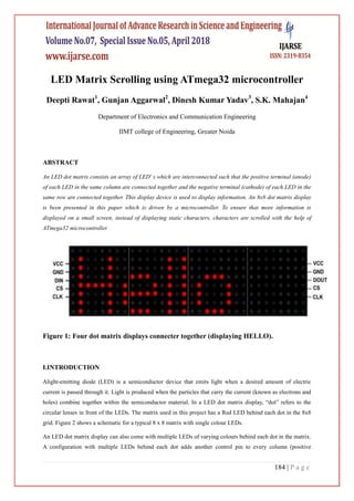
  • 1. 184 | P a g e LED Matrix Scrolling using ATmega32 microcontroller Deepti Rawat1 , Gunjan Aggarwal2 , Dinesh Kumar Yadav3 , S.K. Mahajan4 Department of Electronics and Communication Engineering IIMT college of Engineering, Greater Noida ABSTRACT An LED dot matrix consists an array of LED' s which are interconnected such that the positive terminal (anode) of each LED in the same column are connected together and the negative terminal (cathode) of each LED in the same row are connected together. This display device is used to display information. An 8x8 dot matrix display is been presented in this paper which is driven by a microcontroller. To ensure that more information is displayed on a small screen, instead of displaying static characters, characters are scrolled with the help of ATmega32 microcontroller. Figure 1: Four dot matrix displays connecter together (displaying HELLO). I.INTRODUCTION Alight-emitting diode (LED) is a semiconductor device that emits light when a desired amount of electric current is passed through it. Light is produced when the particles that carry the current (known as electrons and holes) combine together within the semiconductor material. In a LED dot matrix display, “dot” refers to the circular lenses in front of the LEDs. The matrix used in this project has a Red LED behind each dot in the 8x8 grid. Figure 2 shows a schematic for a typical 8 x 8 matrix with single colour LEDs. An LED dot matrix display can also come with multiple LEDs of varying colours behind each dot in the matrix. A configuration with multiple LEDs behind each dot adds another control pin to every column (positive
  • 2. 185 | P a g e terminal) for each additional colour of LED, while the rows (negative terminals) are still all connected together. Therefore an RGB matrix has 32 control pins compared to the 16 pins seen in Figure 2. The desired character or graphics can be displayed by switching ON/OFF a desired configuration of LED‟s. Common display configurations available are 7×5, 8×8, 7×15, etc. LED dot matrix can be used in simple display applications where the resolution is not a big concern. The desired character or graphics can be displayed by switching ON/OFF a desired configuration of LED‟s. Common display configurations available are 7×5, 8×8, 7×15, etc. LED dot matrix can be used in simple display applications where the resolution is not a big concern. Since all of the individual LED‟s in a matrix share their negative and positive terminals in each row and column, it is not possible to control each individual LED at the same time. Figure 2: 8x8 LED matrix schematics The matrix is controlled by cycling through each row very quickly while triggering the correct column pins to light the desired LED‟s for that particular row. If the switching is done at a quick enough rate, there will be no visible flicker and the LED matrix display will appear to have each LED turned on at the same time. This works because of the principle known as Persistence of Vision, which is the theory that the retina of the human eye retains an image for about a tenth of a second. Thus an LED matrix must be very precisely controlled, with the Rows being scanned through sequentially at a rate greater than about 40Hz (to be safe) while sending out the column data at the exact same rate. This kind of control is most easily accomplished with the aid of a microcontroller, plus some additional components. LED dot matrices are very popular means of displaying information as it allows both
  • 3. 186 | P a g e static and animated text and images. Perhaps, you have encountered them at gas stations displaying the gas prices, or in the public places and alongside highways, displaying advertisements on large dot matrix panels. Figure 3: LED dot matrix of different sizes The microcontroller that we used to accomplish this task is ATmega32, which is a member of AVR microcontroller family. The Atmel AVR ATmega32 is a low-power CMOS 8-bit microcontroller based on the AVR enhanced RISC architecture. By executing powerful instructions in a single clock cycle, the ATmega32 achieve throughputs approaching 1 MIPS per MHz allowing the system designed to optimize power consumption versus processing speed. In order to maximize performance and parallelism, the AVR uses Harvard architecture – with separate memories and buses for program and data. Instructions in the program memory are executed with a single level pipelining. While one instruction is being executed, the next instruction is pre-fetched from the program memory. This concept enables instructions to be executed in every clock cycle. The program memory is In-System Reprogrammable Flash memory . Figure 3: ATmega32 IC For the software simulation purpose, the Proteus simulator is used. Proteus is a Virtual System
  • 4. 187 | P a g e Modeling and circuit simulation application. The suite combines mixed mode SPICE circuit simulation, animated components and microprocessor models to facilitate co-simulation of complete microcontroller based designs. Proteus also has the ability to simulate the interaction between software running on a microcontroller and any analog or digital electronics connected to it. It simulates Input / Output ports, interrupts, timers, USARTs and all other peripherals present on each supported processor. In Proteus simulator, there are various virtual components available including dot matrices, microcontrollers, power supply, wires, etc. The tool that we used to write the embedded C program is, ATMEL STUDIO 6. Atmel Studio 6 is the integrated development platform (IDP) for developing and debugging Atmel SMART ARM-based and Atmel AVR microcontroller (MCU) applications. Studio 6 supports all AVR and Atmel SMART MCUs. The Atmel Studio IDP gives you a seamless and easy-to-use environment to write, build and debug your applications written in C/C++ or assembly code. It also connects seamlessly to Atmel debuggers and development kits. The C program is compiled in ATMEL STUDIO and once there‟s no error in the program, it is loaded into the virtual microcontroller in proteus and the simulation can be started and result is thus determined. II.EXPERIMENTAL SECTION Materials & Methods Measurements and Data analysis Materials and Methods The requirements include ATMEGA32, Power supply (5v), an 8x8 LED matrix, AVR ISP Programmer, ATMEL STUDIO. The method to display characters on a LED dot matrix is described below. Now talking about displaying images that we can light any LED we choose it's time to move on to displaying a (small) image. To do this we will use a scan pattern. Here, we define a bitmap image (an array of 8 bytes, each bit representing one LED). Next we scan through this array one byte at a time, displaying one column then the next. If we do this fast enough (about 1000 times a second) it appears as an image. Any individual LED or a group of LEDs in the matrix can be activated by switching the required number of rows and columns. For example, in the following figure 4, if Row1 is made high and Column1 is made low, the top left LED (address R1C1) will glow. As a demonstration, let‟s see how we can display letter “A” using the display. The tables given below shows the logic levels at each pin
  • 5. 188 | P a g e for displaying A.The figure below shows which LEDs are to be turned on to display the English alphabet „A‟. The 7 rows and 5 columns are controlled through the microcontroller pins. Now, let‟s see in detail how it works. Suppose, we want to display the alphabet A. We will first select the column C1 (which means C1 is pulled low in this case), and deselect other columns by blocking their ground paths (one way of doing that is by pulling C2 through C5 pins to logic high). Now, the first column is active, and you need to turn on the LEDs in the rows R2 through R7 of this column, which can be done by applying forward bias voltages to these rows. Next, select the column C2 (and deselect all other columns), and apply forward bias to R1 and R5, and so on. Therefore, by scanning across the column quickly (> 100 times per second), and turning on the respective LEDs in each row of that column, the persistence of vision comes in to play, and we perceive the display as still. The table below, gives the logic levels to be applied to R1 through R7 for each of the columns in order to display the alphabet „A‟. Figure 4 (a): A standard 5x7 LED dot matrix display structure The table below gives the logic levels to be applied to R1 through R7 for each of the columns in order to display the alphabet „A‟.
  • 6. 189 | P a g e Figure 4 (b): Row values of each column for displaying the alphabet A Figure 4 (c): Scanning across the columns and feeding the appropriate row values There are 7 rows and 5 columns and across each row, one pin is sourcing the current for only one LED at a time, but from above, we can see that, a column pin may have to sink the currents from
  • 7. 190 | P a g e more than one LED. For example, the column C1 should be able to sink the currents from 6 LEDs while displaying the alphabet „A‟. As we know that microcontroller faces a limitation i.e. a microcontroller‟s I/O pin cannot sink this much of current, therefore, we need to use internal transistor arrays. Therefore, to solve this problem, we are using ULN2003A IC, which consists of seven built-in Darlington transistor arrays (as shown below in the diagram). As shown below, the inputs of ULN2003A are in an active high state. This means that the input pins must be supplied with a logic high, in order to bring the corresponding output pins to the ground state. The schematic of the Darlington transistor array inside the ULN2003A chip is shown below.
  • 8. 191 | P a g e Figure 5: ULN2003A driver IC The purpose of ULN2003A here is to drive the column lines of the display. ULN2003A is a high voltage (50V), high current (500mA per channel) darlington transistor array. Each IC has 7 channels with individual output clamp diodes. ULN2003A an active high device, which means a logic high must be applied to the input to make the corresponding output high. The input pins are designated as 1B, 2B, 3B, 4B, 5B, 6B, 7B while corresponding output pins are designated as 1C, 2C, 3C, 4C, 5C, 6C, 7C. The pin configuration and simplified internal logic of ULN2003A is shown in the figure below.
  • 9. 192 | P a g e To program the LED dot matrix, we have used AVR (ATmega32) microcontroller. AVR microcontrollers are quite versatile and have various features compared to other well known microcontrollers. AVR family is having inbuilt EEPROM, ADC, specific function pins, More ROM and RAM,RISC architecture, while 8051 doesn't have a inbuilt EEPROM, require external ADC IC, doesn't have specific functions such as AVR, less RAM and ROM compared to AVR,CISC architecture. Also, it uses modified Harvard architecture. Here are certain reasons, why we preferred AVR Studio over other platforms: ATMEL AVR studio is a free IDE developed by ATMEL Corporation (Now Microchip) for their AVR and ARM series of microcontrollers like ATmega32. It supports only ATMEL manufactured Microcontrollers. It also has support for open source debugging and programming tools like USBtinyISP. It is widely used by both amateurs and industry professionals. We used Proteus Design Suite, which is a proprietary software tool suite used primarily for electronic design automation. The software is used mainly by electronic design engineers and electronic technicians to create electronic schematics and electronic prints for manufacturing printed circuit boards. Proteus is a Virtual System Modelling and circuit simulation application. The suite combines mixed mode SPICE circuit simulation, animated components and microprocessor models to facilitate co-simulation of complete microcontroller based designs.Proteus also has the ability to simulate the interaction between software running on a microcontroller and any analog or digital electronics connected to it. It simulates Input / Output ports, interrupts, timers, USARTs andall other peripherals present on each supported processor.  Measurements and Data analysis Snapshots of Proteus Simulation:
  • 10. 193 | P a g e Snapshot of Hardware Simulation:
  • 11. 194 | P a g e
  • 12. 195 | P a g e III.CONCLUSION In the paper, it is evident that both software simulation and hardware simulation of the project of displaying characters on a LED dot matrix using ATMEGA32 microcontroller has been accomplished successfully. REFERENCE [1.] LED Scrolling Display using Android Phone,Deshmukh V. R.1 Karande N. D.2 Patil S. S.3 Tamboli A. S.4 [2.] Scrolling Led Display, AnuradhaMujumdar, 2Vaishali Niranjane, 3DeepikaSagne [3.] LED SCROLLING DISPLAY,Hardik Gupta, Puja Shukla, AnkitaNagwekar [4.] A Survey of Light Emitting Diode (LED) Scrolling Matrix, GowrishankarKasilingam* ,MrithaRamalingam and Chandra Sekar.