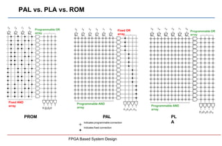
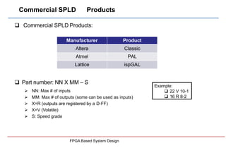
SlideShare a Scribd company logo
1 of 88
Download to read offline
FPGA Based System Design
Outline
FPGA Based System Design
 Introduction
 Simple Programmable Logic Designs (SPLDs)
 PLA
 PAL
 Complex Programmable Logic Designs (CPLDs)
 Field-Programmable Gate Array (FPGAs)
 Logic Blocks
 Programmable Routing Switches
 I/O Pads
 Commercial FPGA Products: Xilinx and Altera
Outline
FPGA Based System Design
 Introduction
 Simple Programmable Logic Designs (SPLDs)
 PLA
 PAL
 Complex Programmable Logic Designs (CPLDs)
 Field-Programmable Gate Array (FPGAs)
 Logic Blocks
 Programmable Routing Switches
 I/O Pads
 Commercial FPGA Products
 Application Specific Integrated Circuits (ASICs)
Introduction: Digital System Design
I. Conventional Approach:
 Board-based designs
 Large # of chips (containing basic logic gates) on a single Printed Circuit Board (PCB)
7404
7408 7432
PCB
Board
X
1
X
2
X
3
Out
VDD
FPGA Based System Design
Introduction: Digital System Design
FPGA Based System Design
II. High-density Single Chip
 A single chip replaces the whole multi-chip design on PCB
 Programmable Logic Designs (PLDs) or
 Application Specific Integrated Circuits (ASICs)
 Lower overall cost
 On-chip interconnects are many times faster than off-chip wires
 Lower area with the same functionality
 Lower power consumption
 Lower noise
Programmable Logic Designs (PLDs)
PLDs
PLA PAL
CPLD FPGA
SPLD Semi-Custom Full-Custom
Digital IC
ASIC
Standard cell Gate Array
This course
FPGA Based System Design
Technology Timeline
The white portions of the timeline bars indicate that although early incarnations of these technologies may
have been available, they weren’t enthusiastically received by the engineers working in the
trenches during this period. For example, although Xilinx introduced the world’s first FPGA as early as
1984, design engineers didn’t really start using it until the early 1990s.
FPGA Based System Design
Simple Programmable Logic Designs (SPLDs)
 Field Programmable Logic Arrays (FPLA or PLA)
 Introduced in early 1970s by Philips
 Consists of two levels of logic gates
 Programmable “wired” AND-plane
 Programmable “wired” OR-plane
 Two levels of programmability
 Well-suited for implementing functions in
sum-of-product (SOP) form.
f1  x1x2  x1x3  x1x2 x3 f2 
x1x2  x1x3  x1x2x3
f1
P1
P2
f2
x1 x2 x3
OR plane
Programmable
AND plane
FPGA Based System Design
connections
P3
P4
SPLD: Programmable Logic Arrays (PLA)
 Each “AND” gate or “OR” gate can have many inputs
 Wide AND/OR gates
f1
P1
P2
x1 x2
OR plane
AND plane
P3
P4
f2
 x1x3
 x1x3
x3
f1 x1x2  x1x2x3
 x1x2x3
f2 x1x2
f1
P1
P2
f2
x1 x2 x3
OR plane
AND plane
Programmable
connections
P3
P4
Unwanted
connections
are “blown”
FPGA Based System Design
Short-hand notation
SPLD: PLAs
FPGA Based System Design
 Advantages:
 PLA is efficient in terms of its required area for its implementation on IC
 Often used as part of larger chips, e.g., microprocessors
 Drawbacks:
 Two-level programmable logic planes are difficult to fabricate
 Two-level programmable structure introduces significant propagation delay
 Normally many pins, large package thus, high fabrication cost
To overcome these drawbacks, PAL was introduced
SPLD: Programmable Array Logic (PAL)
 PAL:
 Consists of two levels of logic gates
 Programmable “wired” AND-plane
 Fixed OR-gates
 Single level of programmability
 Advantages:
 Simpler to fabricate
 Better performance
 Drawbacks:
 Less flexibility
f1  x1x2x3 x1x2x3
f2  x1x2x3  x1x2
f1
P1
P2
f2
x1 x2 x3
AND
plane
P3
P4
FPGA Based System Design
Fixed
OR
SPLD: Programmable Array Logic (PAL)
 To increase flexibility:
 PALs with various sizes of OR-gates.
 Add extra circuitry to the OR-gate output (Called “Macrocell”)
f1
To AND plane
Clk
Select
Enable
Flip-Flop
D Q
0/1
Macrocel
l
Allows Flip-
flop
bypass
Used to
connect/disconnet
to the output pin
To
complemen
t if needed
For implementation of circuits that
have multiple stages of logic
gates
Each macrocell ~ 20 gates
FPGA Based System Design
PAL vs. PLA vs. ROM
PROM PAL
Indicates programmable connection
Indicates fixed connection
PL
A
I 5 I 4 I 3 I 2 I 1 I0
O 3O 2O 1O 0
Programmable AND
array
I5 I4 I3 I2 I1 I0
O 3O 2O 1O 0
Programmable AND
array
Fixed OR
array
O O O O
FPGA Based System Design
3 2 1 0
I3 I2 I1 I0
Fixed AND
array
Programmable OR
array
Programmable OR
array
Commercial SPLD Products
FPGA Based System Design
 Commercial SPLD Products:
 Part number: NN X MM – S
 NN: Max # of inputs
 MM: Max # of outputs (some can be used as inputs)
 X=R (outputs are registered by a D-FF)
 X=V (Volatile)
 S: Speed grade
Manufacturer Product
Altera Classic
Atmel PAL
Lattice ispGAL
Example:
 22 V 10-1
 16 R 8-2
PAL: 22V10 (Lattice Semiconductors)
 Maximum of 22 inputs
 11 inputs, one clock, 10 in/outs
 10 inputs/outputs
 Variable OR gates (8 to 16 inputs)
AND
Plane
Macrocell
#1
8
Preset
In/Out
11
Clk
Macrocell
#2
10
In/Out
Macrocell
#3
12
In/Out
Macrocell
#10
8
In/Out
Inputs
FPGA Based System Design
SPLD Scalability
 It is very hard to scale SPLDs for more complex designs
 b/c the structure of the logic planes grow too quickly in size as
the # of inputs increases
 Solution:
 Integrate multiple SPLDs onto a single chip
 Plus internal programmable interconnect to connect them together
Complex PLDs
(CPLD)
FPGA Based System Design
CPLD
 Consists of 2 to 100 PAL blocks
 Interconnection contains programmable switches
 The number of switches is critical
 Commercial CPLDs:
I/O
block
PAL
block
I/O
block
I/O
block
I/O
block
Interconnection wires
PAL
block
PAL
block
PAL
block
Manufacturer Product
Altera MAX 7000, MAX 10K
Atmel ATF
Xilinx XC9500
AMD Mach series
ICT PEELArray
Lattice ispLSI series
FPGA Based System Design
CPLD: Altera MAX7000
 Comprises:
 Several Logic Array Blocks (LAB), a set of 16 macrocells
 Programmable Interconnect Array (PIA)
 Consists of set of wires that span the entire device
 Makes connections between macrocells and chip’s input/output pins
 In total consists of 32 to 512 macrocells
 Four dedicated input pins
 For global clock or FF resets LAB
LAB
LAB
LAB
LAB
PIA
Altera MAX 7000
LAB
FPGA Based System Design
CPLD: Altera MAX7000
LAB
LAB
LAB
LAB
LAB
LAB
PIA
Altera MAX
LA
LAB (Logic Array Block)
FPGA Based System Design
CPLD: Altera MAX7000
 Comprises:
 Wide programmable AND array followed by
 A narrow fixed OR array
 OR gate can be fed from:
 Any of the five product terms within the macrocell
 or up to 15 extra product terms from other macrocells in the same LAB
more flexibility
FPGA Based System Design
CPLD: Altera MAX7000 Interconnect Architecture
LAB2
PIA
LAB1
LAB6
tPIA
tPIA
column channel row channel
LA
B
Array-based (MAX 3000, 7000)
 Fixed routing delay b/w blocks
 Simple and predictable delay
 Not scalable to large # of macrocells
FPGA Based System Design
Mesh-based (MAX 9000, 10K)
 LABs can connect to row and column channels
 Suitable for large # of macrocells (512)
Advanced Micro Devices (AMD) CPLDs:
 Mach family (Mach 1 to Mach 5) all EEPROM-based technology
 Mach 1, 2: Multiple 22V16 PALs
 Mach 3, 4, 5: Several optimized 34V16 PALs
 Mach 4:
 Consists of:
 6 to 16 PAL (2K-5K gates)
 Central switch matrix
 In-circuit programmable
34V16
34V16
34V16
34V16
34V16
34V16
34V16
34V16
34V16
34V16
34V16
34V16
34V16
I/O
I/O
I/O
I/O
I/O 34V16 34V16 34V16
I/O
I/O
I/O
I/O
I/O
Central Switch Matrix Clk
FPGA Based System Design
All connections b/w PALs and even inside a PAL
routed through the central switch matrix
AMD Mach 4 PAL Block:
FPGA Based System Design
 34V16 (34 maximum inputs, volatile, max 16 outputs)
 In addition to a normal PAL, it consists of:
 product term allocator b/w AND plane and macrocells, which distributes
product terms to whichever OR-gate required
 Output switch matrix b/w OR gates and I/O
Any macrocell can
drive any of the I/O
pins (more flexibility)
CPLD Applications:
FPGA Based System Design
 Circuits that can exploit wide AND/OR gates and do not need large
number of flip-flops
 Graphic controllers
 LAN controllers
 UARTs
 Cache control
 Advantages:
 Easy to re-program even in-system
 Predictability of circuit implementation
 High-speed implementation
Circuit Size Metric
 Size Metric:
 How many basic gates can be built on the circuit
 Common measure: number of two-input NAND gates
Device Size Design Type
SPLD ~ 200 gates Small
CPLD ~ 10,000 gates Moderate
FPGA ~ 1,000,000 gates Large
Equivalent
gates
2,000,000
200,000
2000
200
SPLD
s
FPGA Based System Design
CPLD
s
FPGA
s
Outline
 Introduction
 Simple Programmable Logic Designs (SPLDs)
 PLA
 PAL
 Complex Programmable Logic Designs (CPLDs)
 Field-Programmable Gate Array (FPGAs)
 Logic Blocks
 Programmable Routing Switches
 I/O Pads
 Commercial FPGA Products
 Application Specific Integrated Circuits (ASICs)
Programmable Logic Designs (PLDs)
PLDs
PLA PAL
CPLD FPGA
SPLD Semi-Custom Full-Custom
Digital IC
ASIC
Standard cell Gate Array
FPGA Based System Design
FPGA
FPGA Based System Design
 FPGA: (Field-Programmable Gate Array)
 Pre-fabricated silicon devices that can be electrically programmed to become any
kind of digital circuit or system
 A very large array of programmable logic blocks surrounded by programmable
interconnects
 Contains logic blocks instead of AND/OR planes (multi-level logic of arbitrary depth)
 Can be programmed by the end-user to implement specific applications
 Capacity up to multi-millions gates
 Clock frequency up to 500MHz
FPGA Applications
FPGA Based System Design
 Popular applications:
 Prototyping a design before the final fabrication (using single FPGA)
 Emulation of entire large hardware systems (using multiple FPGAs)
 Configured as custom computing machines
 Using programmable parts to “execute” software rather than software
compilation on a CPU
 On-site hardware reconfiguration
 Low-cost applications
 DSP, logic emulation, network components, etc…
FPGA Structure
 FPGAs consists of 3 main resources:
1. Logic Blocks
 General logic blocks
 Memory blocks
 Multiplier blocks
2. Program. Routing Switches
 Programmable horizontal/vertical
routing channels
 Connecting blocks together and I/O
3. I/O Blocks
 Connecting the chip to the outside
Logic
Block
Memory
Logic
Block
Multiplier
Logic
Block
Memory
Logic
Block
Multiplier
Logic
Block
Memory
Logic
Block
Multiplier
Logic
Block
Memory
Logic
Block
Multiplier
I/O Block Programmable
Routing Switches
FPGA
Fabrics
FPGA Based System Design
Modern Commercial FPGAs
FPGA Based System Design
Modern Commercial FPGAs
FPGA Based System Design
 The concept of coupling microprocessors with FPGAs in heterogeneous
platforms was considerably attractive.
 In this programmable platform, microprocessors implement the control-
dominated aspects of DSP systems and FPGAs implement the
data- dominated aspects.
 With FPGAs, the user is given full freedom to define the architecture
which best suits the application.
FPGA Categories (Fabrics)
 There are two main categories of FPGAs in terms of their fabrics:
 SRAM-based FPGAs (Xilinx, Altera) [Re-programmable, Re-configurable]
 Using Lookup Tables (LUTs) to implement logic blocks
 Using SRAM-cells to implement programmable switches
 Antifuse-based FPGAs (Actel, Lattice, Xilinx, QuickLogic, Cypress)
[Permanent]
 Using multiplexers (MUXs) to implement logic blocks
 Using antifuses to implement programmable switches
SRAM-
Based
FPGAs
Antifuse-
Based
LUT-
Based
Logic
Blocks
SRAM-
Based
Switches
MUX-
Based
Logic
Blocks
Antifuse-
Based
Switches
Re-
programmable
Permanen
t
FPGA Based System Design
Outline
 Introduction
 Simple Programmable Logic Designs (SPLDs)
 PLA
 PAL
 Complex Programmable Logic Designs (CPLDs)
 Field-Programmable Gate Array (FPGAs)
 Logic Blocks
 Programmable Routing Switches
 I/O Pads
 Commercial FPGA Products
 Application Specific Integrated Circuits (ASICs)
Logic Block
FPGA Based System Design
 The logic block is the most important element of an FPGA, which provides the
basic computation and storage elements used in digital logic systems
 Logic blocks are used to implement logic functions
 A logic block has a small number of inputs and outputs
 The logic block of an FPGA is considerably more complex than
a standard CMOS gate b/c:
 A CMOS gate implements only one chosen logic function
 An FPGA logic block must be configurable enough to implement a number of
different functions
LUT-Based Logic Block (Used in SRAM-Based FPGAs)
x1 x2 f
0 0 a
0 1 b
1 0 c
1 1 d
0
1
0
1
f
0
1
x2
a
b
c
d
 Lookup Table (LUT)
 Uses a set of 1-bit storage elements to implement logic functions
 Example:
 A 2-input LUT
 Capable of implementing any logic function of two variables
x1
SRAM Cell
FPGA Based System Design
LUT-Based Logic Block
 Lookup Table (LUT) consists of:
 Memory (SRAM Cells)
 Configuration circuit that selects the proper memory bit
0
1
0
1
f
0
1
x2
a
b
c
d
x1
SRAM Cell
f
d
c
b
a
x1
x2
SRAM Cells
Configuration Circuit
FPGA Based System Design
MUX-Based Logic Block (Used in Antifuse-Based FPGA)
 The logic block in antifuse-based FPGAs are generally based on
multiplexing
 Functions can be realized using MUXs based on Shannon’s expansion
 Shannon’s Expansion Theorem:
Any logic function f(x1, x2, …, xn) can be expanded in the form of:
xk. f(x1, x2, xk-1,1,xk+1,…, xn)+ xk’. f(x1, x2, xk-1,0,xk+1,…, xn)
 Example:
 F(A, B, C) = A’B + ABC’ + A’B’C
= A.F(1,B,C) + A’.F(0,B,C)
= A(BC’) + A’(B+B’C)
FPGA Based System Design
MUX-Based Logic Block
AND Gate:
FAND = A.B = A.B +A’0
0
1
A
0
B
FAND
OR Gate:
FOR = A+B = A.1 +A’B
XOR Gate:
FAND =AB’+A’B
0
1
A
B
1
FO
R
0
1
A
B
B’
F
FPGA Based System Design
XO
R
Comparison b/w MUX-based and LUT-based
FPGA Based System Design
 LUT-based Logic Block (LB) using SRAM cells:
 An n-input LUT function requires 2n SRAM cells
 Each SRAM cell requires 8 transistors
 e.g., a 4-input function requires 16x8=128 transistors
 Decoding circuitry is also required
 e.g., decoder for a 4-input LUT is a MUX with 96 transistors
 Delay of LUT is independent of the function implemented and is
dominated by the delay through the SRAM cell (same for all functions!)
 SRAM consumes power even when its inputs do not change. The stored
charge in the SRAM cell dissipates slowly.
 LUT-based LB is considerably more expensive than a static CMOS gate.
 Easier implementation through loading configuration bits
Comparison b/w MUX-based and LUT-based
FPGA Based System Design
 MUX-based LB using Static CMOS:
 Number of transistors a function of number of inputs and the function
 An n-input NAND requires 2n transistors
 An n-input XOR is more complicated
 The delay of a static gate depends on the number of inputs, function,
and the transistor sizes
 MUX-based implementation consumes no power while the inputs are
stable (ignoring the leakage power)
 Synthesizer has a hard time figuring out how to implement a certain
function into the given MUX structure
Outline
 Introduction
 Simple Programmable Logic Designs (SPLDs)
 PLA
 PAL
 Complex Programmable Logic Designs (CPLDs)
 Field-Programmable Gate Array (FPGAs)
 Logic Blocks
 Programmable Routing Switches
 I/O Pads
 Commercial FPGA Products
 Application Specific Integrated Circuits (ASICs)
Programmable Switches
Logi
c
Bloc
k
Memory
Logi
c
Bloc
k
Multiplier
Logi
c
Bloc
k
Memory
Logi
c
Bloc
k
Multiplier
Logi
c
Bloc
k
Memory
Logi
c
Bloc
k
Multiplier
Logi
c
Bloc
k
Memory
Logi
c
Bloc
k
Multiplier
SRAM-Cell-Based
FPGA Based System Design
Antifuse-Based
EPROM transistor-
Based
SRAM-Based Programmable Switches
Logic Blocks
FPGAs
Prog. Switches
MUX-Based
Antifuse-Based
Switches
I/O Blocks
LUT-Based
FPGA Based System Design
SRAM-Based
Switches
Flash/EEPROM
SRAM-Based Programmable Switches
 SRAM Cell is used both in logic blocks and the Prog.
Interconnections:
SRAM
Cell
SRAM
Cell
SRAM
Cell
SRAM
Cell
SRAM
Cell
SRAM
Cell
SRAM
Cell
SRAM
Cell
SRAM
Cell
SRAM
Cell
SRAM
Cell
SRAM
Cell
SRAM
Cell
SRAM
Cell
SRAM
Cell
SRAM
Cell
SRAM
Cell
SRAM
Cell
SRAM
Cell
SRAM
Cell
Logic Cell Logic Cell
Programmable
Interconnect
1 1
2
2
2
SRAM
Cell
A B
A B
1
B
0
A
Pass
Transistor
FPGA Based System Design
Programming FPGAs
 Programming an FPGA by configuring Logic Blocks & Routing
x3 f
X1 0
0
0
X2 1
FPGA Based System Design
x
x2 0
1
0
3 0
f 1 0
1
1
1
f 2
f
1
f 2
f
x1
x2
SRAM-Based Programmable Switches
FPGA Based System Design
 Advantages:
 Re-programmability (infinite number of times)
 Use of standard CMOS fabrication process technology
 Use of the latest CMOS technology
 Benefits from increased integration, higher speed, lower dynamic power
 Drawbacks:
 Size: SRAM cell requires 6 transistors
 Volatility: an external device (like an EPROM) is needed to permanently store the
configuration bits when the device is powered down (extra cost)
 Non-ideal pass transistors: SRAM cells rely on pass transistors that have
large on-resistance and capacitance load
 Reliability: the bits in the SRAM are susceptible to theft
Antifuse-Based Programmable Switches
Logic Blocks
FPGAs
Prog. Switches
MUX-Based
Antifuse-Based
Switches
I/O Blocks
LUT-Based
SRAM-Based
Switches
Flash/EEPROM
FPGA Based System Design
Antifuse-Based Programmable Switches
FPGA Based System Design
 The programmable element is an antifuse
 Programmed by applying a voltage across it
 Normal condition: high resistance link
 When programmed (blown): low resistance (20-100 Ohm)
 Permanently programmed (unlike SRAM)
 Why antifuse and not fuse?
 Well, interconnect networks are sparsely populated, which means that
most of them are not connected
 So antifuse is used, which is an open circuit by default
A high voltage blows the antifuse so it conducts
Antifuse-Based Programmable Switches
 Two general structures:
Metal 2
Antifuse
Via
Metal 1
polysilico
n
FPGA Based System Design
dielectric
n+
diffusion
Oxid
e
A
B
A
B
Silicon
substrate
Metal to Metal (Via Link)
Poly to Diffusion (Actel)
EEPROM/Flash-Based Programmable Switches
Logic Blocks
FPGAs
Prog. Switches
MUX-Based
Antifuse-Based
Switches
I/O Blocks
LUT-Based
FPGA Based System Design
SRAM-Based
Switches
Flash/EEPROM
EEPROM/Flash-Based Programmable Switches
 Flash memory is a high-quality programmable read-only memory
 Has a floating gate structure, where a low-leakage capacitor holds a
voltage that controls a transistor gate
 This memory cell can be used to control programming transistors
A B
g=1
B
g=0
A
g
A
Programmabl
e Transistor
(large)
Floating Gate
(stores charge once
programmed)
Flash
Transisto
r (small)
B
Gate control
(set to LOW voltage for programming)
FPGA Based System Design
M1 M2
set to HIGH for programming
(Injects charge)
EEPROM/Flash-Based Programmable Switches
An EEPROM transistor is also used as a programmable switch for CPLDs by
placing the transistor between two wires in a way that facilitates implementation of
wired-AND functions.
 An input to the AND plane can drive a product wire to ‘0’
EEPRO
M
EEPRO
M
In2
In1
Product wire
VDD
FPGA Based System Design
EEPROM/Flash-Based Programmable Switches
 Advantages:
 Non-volatile Does not lose information when the device is powered off
(Thus no extra memory/flash is required)
 Improved area efficiency (less transistors needed compared to SRAM-cell)
 Re-programmable
 Drawbacks:
 Tricky floating-gate design
 source-drain voltage should be low enough to prevent charge injection
into the floating gate
 Can NOT be reprogrammed infinite number of times!
 b/c of charge build-up in the oxide (e.g., Actel ProASIC3 are rated for 500 times)
 Uses non-standard CMOS process
 High resistance and capacitance due to the use of transistor-based switches
FPGA Based System Design
Programmable Switches
FPGA Based System Design
 So there are three technologies for switches:
 SRAM cell
 Antifuse
 Flash-based
 The ideal technology is the one that is:
 Non-volatile
 Reprogrammable infinite number of times
 Based on standard cell CMOS process
 Offer low on resistance and capacitance
 Recent trend by Xilinx, Altera and Lattice:
 On-chip flash memory for storage of configuration bits
 SRAM-based interconnect switches
Comparison Between All Technologies
FPGA Based System Design
Manufacturer SRAM Flash/EEPROM Antifuse
Volatile Yes No No
Re-Programmable Yes Yes No
Area High (6 transistors) Moderate(1 transistor) Low(0 transistor)
Manufacturing Process Standard CMOS Flash
Process(EECMOS)
Antifuse (CMOS+)
In-system Programmable Yes Yes No
Switch Resistance 500-1000 Ohm 500-1000 Ohm 20-100 Ohm
Switch Capacitance 1-2fF 1-2fF <1 fF
Yield 100% 100% >90%
Routing Channels
Logic
Block
Logic
Block
Logic
Block
Logic
Block
0
FPGA Based System Design
1
Interconnect wiring is grouped into routing channels, each of which
contains a complete grid of horizontal and vertical wires.
Routing Channels
FPGA Based System Design
FPGA wiring with programmable interconnect is slower than typical wiring in a
custom chip b/c:
 Pass transistor on an interconnect is not a perfect on-switch
Programmable interconnect is slower than a pair of wires permanently
connected by a via
 FPGA wires are generally longer than would be necessary for a custom chip
Outline
 Introduction
 Simple Programmable Logic Designs (SPLDs)
 PLA
 PAL
 Complex Programmable Logic Designs (CPLDs)
 Field-Programmable Gate Array (FPGAs)
 Logic Blocks
 Programmable Routing Switches
 I/O Pads
 Commercial FPGA Products
 Application Specific Integrated Circuits (ASICs)
118
FPGA Chip I/O
FPGA Based System Design
 I/O pins on a chip connect it to the outside world and perform some basic
functions
 Input pins provide electrostatic discharge (ESD) protection
 Output pins provide buffers with sufficient drive to produce adequate signals
on the pins
 Three-state pins include logic to switch b/w input and output modes
 The pins on an FPGA can be configured to act as
 Input pin
 Output pin
 Tri-state pin
Xilinx Spartan II 2.5V Family I/O Pins
 Supports a wide range of I/O standards
 The I/O has three registers, one each for input, output and tri-state operation
 Each has its own enable signal
 They all share the same clock connection
 Can be configured as latch or FF
Clk
0
1
Clk
Clk
T
Input
Output
0
1
Programmable
delay
ProgrammableBias &
ESD Protection
Programmable
Outputbuffer
Programmable
Inputbuffer
0
1
I/OVref
I/O
VCCO
Internal
Interface
TonextI/O
The Prog. delay on the input path
is to eliminate variations in hold
times from pin to pin
FPGA Based System Design
Xilinx Spartan II 2.5V Family I/O Pins
FPGA Based System Design
 Supports a wide range of I/O standards, divided into eight banks
 Pads within each bank share the same reference voltage, threshold voltage
and use standards that have the same VCCO
I/O Standard Input Ref. Voltage (Vref) Output Source Voltage
(VCCO)
LVTTL N/A 3.3
LVCMOS2 N/A 2.5
PCI N/A 3.3
GTL 0.8 N/A
HSTL Class I 0.75 1.5
SSTL3 Class I/II 1.5 3.3
CTT 1.5 3.3
AGP-2X 1.32 3.3
Outline
 Introduction
 Simple Programmable Logic Designs (SPLDs)
 PLA
 PAL
 Complex Programmable Logic Designs (CPLDs)
 Field-Programmable Gate Array (FPGAs)
 Logic Blocks
 Programmable Routing Switches
 I/O Pads
 Commercial FPGA Products
 Application Specific Integrated Circuits (ASICs)
122
Commercial FPGA Products
FPGA Based System Design
Manufacturer FPGA Products LUT/Antifuse based Floorplan
Actel MX, SX, eX, Axcelerator Antifuse-based Row-Based
QuickLogic PASIC, QuickRAM,
Eclipse (Plus/II)
Antifuse-based Symmetrical array
Lattice ECP2/M, SC Antifuse-based Symmetrical array
Atmel AT40K, AT40KAL LUT-Based Hierarchical PLD
Altera Stratix (II/III/IV),
Cyclone (II/III),
Arria (II), Flex 8000, 10K
LUT-based
Hierarchical PLD
Xilinx Virtex-II Pro, Virtex-(E,4,5,6)
Spartan-(II/3) (A/E), XC4000
LUT-based Symmetrical array
Commercial FPGA Products
FPGA Based System Design
 Xilinx:
 SRAM-Based:
 XC2000
 XC3000
 XC4000
 XC5000
 Virtex Family (II Pro, 4, 5, 6)
 Spartan Family
 Antifuse-Based:
 XC8100
Xilinx (XC4000 Series)
FPGA Based System Design
 2,000 to 15,000 gates (XC4085 supports up to 100,000 gates)
 The building block in Xilinx FPGAs is called Configurable Logic Block (CLB)
 XC4000 CLB is LUT-based and consists of
 3 LUTs (two 4-input and one 3-input)
 2 Flip-Flops (FFs)
 These 3 LUTs allow implementation of:
 Logic functions of up to 9 inputs
 Two separate 4-input functions
Each CLB contains circuitry that allows
Implementation of fast carry operations
(soft logic, coarse-grained)
Xilinx (XC4000 Series): Interconnect
FPGA Based System Design
 Consists of horizontal and vertical channels
 Wires in each channel in XC4000 series are of different types
 Wire segments: of length 1, 2, 4 (single, double, quad)
 Direct interconnect: For local connections, with min delay, small fan-out
 Effective for implementation of fast arithmetic modules
 Long Wires: for global routing, high fan-out,
 Used for time critical signals or signals distributed over long distances (Bus)
 Special wires: for clock routing
LUTs in a CLB can be configured as read/write RAM cells
Xilinx (XC4000 Series): Interconnect
 Interconnect Architecture:
Numbers show the number of wires of each type
2
12
8
4
3
2
3
CLB
4 8 4
Quad
Single
Double
Long
Direct
Connect
Direct
Connect
Quad Long Global
Clock
8
Long Double Single Global
Clock
Carry
Chain
Long
12 4 4 4
FPGA Based System Design
Commercial FPGA Products
FPGA Based System Design
 Altera:
 SRAM-Based:
 FLEX 8000
 FLEX 6000
 FLEX 10000
 Cyclone II/III
 Stratix II, III, IV
Altera (FLEX 8000 Series)
FPGA Based System Design
 The logic block in Altera FPGAs is called Logic Element (LE)
 FLEX8000 contains three main components
1. The main building block is called Logic Array Block (LAB)
 Contains eight LUT-based LEs
2. FastTrack interconnect
 Horizontal and vertical to connect LABs
3. I/O pads
Altera (FLEX 8000 Series)
FPGA Based System Design
 Architecture of FLEX8000
 LAB
 FastTrack
 I/O
Altera (FLEX 8000 Series)
 Each FLEX8000 LAB is a group of eight LEs
 Each LAB:
 Has a number of inputs provided from the adjacent row interconnect wires
 Its outputs connect to the adjacent row/column wires
 Contains local interconnects to connect any LE to another LE inside the same LAB
 Connected to the global interconnect (fastTrack)
 Similar to the Xilinx long lines
LE 1
4
LE 2
4
LE 8
4
Cntrl
4
Cascade
carry
2
To FastTrack
Interconnect
To FastTrack
Interconnect
To FastTrack
Interconnect
FromFastTrack
Interconnect
data
Toadjacent
LAB
LAB
Local
Interconnects
FPGA Based System Design
Altera (FLEX 8000 Series)
 Each FLEX8000 LE is LUT-based and consists of :
 A 4-input LUT(to implement two 3-input functions, i.e. sum/carry fcns in a full adder)
 A Flip-Flops (FF)
 Carry circuitry
 Cascade circuitry
(soft logic, coarse-grained)
LE 1
4
LE 2
4
LE 8
4
ToFastTrack
Interconnect
ToFastTrack
Interconnect
ToFastTrack
Interconnect
Cntrl
4
Cascade
carry
2
FromFastTrack
Interconnect
data
Toadjacent LAB
K-nput
LUT
Clk
0
1
Carry
Carryin CarryOut
Cascade
Cascade in
Cascade out
Out
Data 1 Data 2
Data3
Data4
Ctrl1
Ctrl2
Ctrl3
Ctrl4
Set/Clear
Clock
LAB
FPGA Based System Design
LE
Commercial FPGA Products
FPGA Based System Design
 Actel:
 Antifuse-Based:
 Act 1
 Act 2
 Act 3
 SX-A
 Axcelerator
Actel FPGAs (Act 3 Series)
 A structure similar to the traditional gate arrays
 Consists of
 Horizontal logic blocks
 Horizontal routing channels
 I/O blocks
 MUX-based logic blocks
 MUX
 AND/OR
 Interconnects:
 Only horizontal
 Segmented wires
 Use antifuse to connect LBs
to routing channels
I/O Blocks
I/O Blocks
I/O
Blocks
I/O
Blocks
Routing
Channels
rows
FPGA Based System Design
Logic Blocks
rows
Actel FPGAs (Act 3 Series)
 Detailed architecture of Act 3:
I/O Blocks
I/O Blocks
I/O
Blocks
I/O
Blocks
0
1
0
1
0
1
s0
s1
B0
A0
A1
SA
B1
S
B
F
0
1
0
1
0
1
0
B
D
“1”
C
D
“1”
A
F
F=(A.B)+(B’.C)+D
Example
FPGA Based System Design
Actel FPGAs (Act 3 Series)
 Detailed architecture of Act 3:
I/O Blocks
I/O Blocks
I/O
Blocks
I/O
Blocks Clock Track
Vertical Track
FPGA Based System Design
PLICE Antifuse
Actel Device Number of Antifuses
A1010 112,000
A1225 250,000
A1280 750,000
Actel FPGAs (Axcelerator Series)
 Advance recent antifuse-based FPGA with 2 million equivalent gates.
 It comes with
 Embedded SRAM Blocks
 Chip-wide highway routing
 Carry logic
 PLL
 AX125 Logic Block:
FPGA Based System Design
Actel FPGAs (ProASIC 500K Series)
FPGA Based System Design
Flash-based FPGA, using switches and MUXs for programmability to implement logic
functions
 The programmed switches are used to select alternate inputs to the core logic
 It can implement any function of 3 inputs except the 3-input XOR
 The feedback paths allow the logic block to be configured as a latch
 in2: clock
 in3: reset
Commercial FPGA Products : Applications
FPGA Based System Design
 Communication:
 Virtex 4/5/6 & Virtex II Pro (Xilinx)
 Stratix II/III/IV & Stratix GX (Altera)
 Consumer Electronics, Automotive &Micro Controllers:
 Spartan 3 (Xilinx)
 Cyclone 2 (Altera)
 ProASIC3/E (Actel)
 Aerospace & Military Applications:
 Axcelerator (Actel)
FPGA Design Flow
FPGA Based System Design
FPGA Design Flow
FPGA Based System Design
FPGA Design Flow: Mapping
FPGA Based System Design
FPGA Design Flow: Mapping
LUT
2
FPGA Based System Design
LUT
3
LUT
4
LUT
5
LUT
1 FF1
FF2
LUT
0
FPGA Design Flow: Placement & Routing
FPGA Based System Design
FPGA Design Flow: Placement
FPGA
CLB SLICES
FPGA Based System Design
FPGA Design Flow: Routing
Programmable
Connections
FPGA
FPGA Based System Design
FPGA Design Flow: In a Glance
FPGA Based System Design

More Related Content

What's hot

Field Programmable Gate Array: Building Blocks and Interconnections
Field Programmable Gate Array: Building Blocks and InterconnectionsField Programmable Gate Array: Building Blocks and Interconnections
Field Programmable Gate Array: Building Blocks and InterconnectionsDr. Saravanakumar Umathurai
 
Introduction to FPGA, VHDL
Introduction to FPGA, VHDL  Introduction to FPGA, VHDL
Introduction to FPGA, VHDL Amr Rashed
 
Power Dissipation of VLSI Circuits and Modern Techniques of Designing Low Pow...
Power Dissipation of VLSI Circuits and Modern Techniques of Designing Low Pow...Power Dissipation of VLSI Circuits and Modern Techniques of Designing Low Pow...
Power Dissipation of VLSI Circuits and Modern Techniques of Designing Low Pow...IJSRD
 
Analog Layout design
Analog Layout design Analog Layout design
Analog Layout design slpinjare
 
Complex Programmable Logic Device (CPLD) Architecture and Its Applications
Complex Programmable Logic Device (CPLD) Architecture and Its ApplicationsComplex Programmable Logic Device (CPLD) Architecture and Its Applications
Complex Programmable Logic Device (CPLD) Architecture and Its Applicationselprocus
 
Electronic Design Automation
Electronic Design AutomationElectronic Design Automation
Electronic Design AutomationCADD Centre
 
Advanced Low Power Techniques in Chip Design
Advanced Low Power Techniques in Chip DesignAdvanced Low Power Techniques in Chip Design
Advanced Low Power Techniques in Chip DesignDr. Shivananda Koteshwar
 
Introduction to FinFET
Introduction to FinFETIntroduction to FinFET
Introduction to FinFETManishKenchi
 
fpga programming
fpga programmingfpga programming
fpga programmingAnish Gupta
 

What's hot (20)

PLDs
PLDsPLDs
PLDs
 
FPGA
FPGAFPGA
FPGA
 
Field Programmable Gate Array: Building Blocks and Interconnections
Field Programmable Gate Array: Building Blocks and InterconnectionsField Programmable Gate Array: Building Blocks and Interconnections
Field Programmable Gate Array: Building Blocks and Interconnections
 
Low Power VLSI Design
Low Power VLSI DesignLow Power VLSI Design
Low Power VLSI Design
 
Fpga Knowledge
Fpga KnowledgeFpga Knowledge
Fpga Knowledge
 
FPGA
FPGAFPGA
FPGA
 
Introduction to FPGA, VHDL
Introduction to FPGA, VHDL  Introduction to FPGA, VHDL
Introduction to FPGA, VHDL
 
Power Dissipation of VLSI Circuits and Modern Techniques of Designing Low Pow...
Power Dissipation of VLSI Circuits and Modern Techniques of Designing Low Pow...Power Dissipation of VLSI Circuits and Modern Techniques of Designing Low Pow...
Power Dissipation of VLSI Circuits and Modern Techniques of Designing Low Pow...
 
Low Power VLSI Designs
Low Power VLSI DesignsLow Power VLSI Designs
Low Power VLSI Designs
 
Unit VI CPLD-FPGA Architecture
Unit VI CPLD-FPGA ArchitectureUnit VI CPLD-FPGA Architecture
Unit VI CPLD-FPGA Architecture
 
Cpld fpga
Cpld fpgaCpld fpga
Cpld fpga
 
Analog Layout design
Analog Layout design Analog Layout design
Analog Layout design
 
Complex Programmable Logic Device (CPLD) Architecture and Its Applications
Complex Programmable Logic Device (CPLD) Architecture and Its ApplicationsComplex Programmable Logic Device (CPLD) Architecture and Its Applications
Complex Programmable Logic Device (CPLD) Architecture and Its Applications
 
ASIC vs SOC vs FPGA
ASIC  vs SOC  vs FPGAASIC  vs SOC  vs FPGA
ASIC vs SOC vs FPGA
 
Electronic Design Automation
Electronic Design AutomationElectronic Design Automation
Electronic Design Automation
 
Advanced Low Power Techniques in Chip Design
Advanced Low Power Techniques in Chip DesignAdvanced Low Power Techniques in Chip Design
Advanced Low Power Techniques in Chip Design
 
dual-port RAM (DPRAM)
dual-port RAM (DPRAM)dual-port RAM (DPRAM)
dual-port RAM (DPRAM)
 
Introduction to FinFET
Introduction to FinFETIntroduction to FinFET
Introduction to FinFET
 
fpga programming
fpga programmingfpga programming
fpga programming
 
Layout rules
Layout rulesLayout rules
Layout rules
 

Similar to 1. FPGA architectures.pdf

Fpga &;cpld(by alok singh)
Fpga &;cpld(by alok singh)Fpga &;cpld(by alok singh)
Fpga &;cpld(by alok singh)Alok Singh
 
Cyclone II FPGA Overview
Cyclone II FPGA OverviewCyclone II FPGA Overview
Cyclone II FPGA OverviewPremier Farnell
 
Programmable lrray Logic
Programmable lrray LogicProgrammable lrray Logic
Programmable lrray Logicrohitladdu
 
L12 programmable+logic+devices+(pld)
L12 programmable+logic+devices+(pld)L12 programmable+logic+devices+(pld)
L12 programmable+logic+devices+(pld)NAGASAI547
 
Synopsys User Group Presentation
Synopsys User Group PresentationSynopsys User Group Presentation
Synopsys User Group Presentationemlawgr
 
Programmable array logic
Programmable array logicProgrammable array logic
Programmable array logicGaditek
 
L12_PROGRAMMABLE+LOGIC+DEVICES+(PLD).ppt
L12_PROGRAMMABLE+LOGIC+DEVICES+(PLD).pptL12_PROGRAMMABLE+LOGIC+DEVICES+(PLD).ppt
L12_PROGRAMMABLE+LOGIC+DEVICES+(PLD).pptMikeTango5
 
Poster digital-070624
Poster digital-070624Poster digital-070624
Poster digital-070624Bertalan EGED
 
Introduction to Advanced embedded systems course
Introduction to Advanced embedded systems courseIntroduction to Advanced embedded systems course
Introduction to Advanced embedded systems courseanishgoel
 
FPGA-Arch (3).ppt
FPGA-Arch (3).pptFPGA-Arch (3).ppt
FPGA-Arch (3).pptArthi579360
 

Similar to 1. FPGA architectures.pdf (20)

Fpga &;cpld(by alok singh)
Fpga &;cpld(by alok singh)Fpga &;cpld(by alok singh)
Fpga &;cpld(by alok singh)
 
VLSI PLDS pla, pal
VLSI PLDS pla, palVLSI PLDS pla, pal
VLSI PLDS pla, pal
 
ASIC VS FPGA.ppt
ASIC VS FPGA.pptASIC VS FPGA.ppt
ASIC VS FPGA.ppt
 
Asic
AsicAsic
Asic
 
Cyclone II FPGA Overview
Cyclone II FPGA OverviewCyclone II FPGA Overview
Cyclone II FPGA Overview
 
Dr.D.RUKMANIDEVI PPT.ppt
Dr.D.RUKMANIDEVI PPT.pptDr.D.RUKMANIDEVI PPT.ppt
Dr.D.RUKMANIDEVI PPT.ppt
 
4_BIT_ALU
4_BIT_ALU4_BIT_ALU
4_BIT_ALU
 
1.CPLD SPLD.pdf
1.CPLD SPLD.pdf1.CPLD SPLD.pdf
1.CPLD SPLD.pdf
 
Programmable lrray Logic
Programmable lrray LogicProgrammable lrray Logic
Programmable lrray Logic
 
Flash memory
Flash memoryFlash memory
Flash memory
 
L12 programmable+logic+devices+(pld)
L12 programmable+logic+devices+(pld)L12 programmable+logic+devices+(pld)
L12 programmable+logic+devices+(pld)
 
Synopsys User Group Presentation
Synopsys User Group PresentationSynopsys User Group Presentation
Synopsys User Group Presentation
 
Programmable array logic
Programmable array logicProgrammable array logic
Programmable array logic
 
L12_PROGRAMMABLE+LOGIC+DEVICES+(PLD).ppt
L12_PROGRAMMABLE+LOGIC+DEVICES+(PLD).pptL12_PROGRAMMABLE+LOGIC+DEVICES+(PLD).ppt
L12_PROGRAMMABLE+LOGIC+DEVICES+(PLD).ppt
 
Cyclone IV FPGA Device
Cyclone IV FPGA DeviceCyclone IV FPGA Device
Cyclone IV FPGA Device
 
Poster digital-070624
Poster digital-070624Poster digital-070624
Poster digital-070624
 
FPGA
FPGAFPGA
FPGA
 
Introduction to EDA Tools
Introduction to EDA ToolsIntroduction to EDA Tools
Introduction to EDA Tools
 
Introduction to Advanced embedded systems course
Introduction to Advanced embedded systems courseIntroduction to Advanced embedded systems course
Introduction to Advanced embedded systems course
 
FPGA-Arch (3).ppt
FPGA-Arch (3).pptFPGA-Arch (3).ppt
FPGA-Arch (3).ppt
 

Recently uploaded

Introduction-To-Agricultural-Surveillance-Rover.pptx
Introduction-To-Agricultural-Surveillance-Rover.pptxIntroduction-To-Agricultural-Surveillance-Rover.pptx
Introduction-To-Agricultural-Surveillance-Rover.pptxk795866
 
TechTAC® CFD Report Summary: A Comparison of Two Types of Tubing Anchor Catchers
TechTAC® CFD Report Summary: A Comparison of Two Types of Tubing Anchor CatchersTechTAC® CFD Report Summary: A Comparison of Two Types of Tubing Anchor Catchers
TechTAC® CFD Report Summary: A Comparison of Two Types of Tubing Anchor Catcherssdickerson1
 
Heart Disease Prediction using machine learning.pptx
Heart Disease Prediction using machine learning.pptxHeart Disease Prediction using machine learning.pptx
Heart Disease Prediction using machine learning.pptxPoojaBan
 
Work Experience-Dalton Park.pptxfvvvvvvv
Work Experience-Dalton Park.pptxfvvvvvvvWork Experience-Dalton Park.pptxfvvvvvvv
Work Experience-Dalton Park.pptxfvvvvvvvLewisJB
 
Comparative Analysis of Text Summarization Techniques
Comparative Analysis of Text Summarization TechniquesComparative Analysis of Text Summarization Techniques
Comparative Analysis of Text Summarization Techniquesugginaramesh
 
Electronically Controlled suspensions system .pdf
Electronically Controlled suspensions system .pdfElectronically Controlled suspensions system .pdf
Electronically Controlled suspensions system .pdfme23b1001
 
8251 universal synchronous asynchronous receiver transmitter
8251 universal synchronous asynchronous receiver transmitter8251 universal synchronous asynchronous receiver transmitter
8251 universal synchronous asynchronous receiver transmitterShivangiSharma879191
 
Software and Systems Engineering Standards: Verification and Validation of Sy...
Software and Systems Engineering Standards: Verification and Validation of Sy...Software and Systems Engineering Standards: Verification and Validation of Sy...
Software and Systems Engineering Standards: Verification and Validation of Sy...VICTOR MAESTRE RAMIREZ
 
Churning of Butter, Factors affecting .
Churning of Butter, Factors affecting  .Churning of Butter, Factors affecting  .
Churning of Butter, Factors affecting .Satyam Kumar
 
Call Girls Delhi {Jodhpur} 9711199012 high profile service
Call Girls Delhi {Jodhpur} 9711199012 high profile serviceCall Girls Delhi {Jodhpur} 9711199012 high profile service
Call Girls Delhi {Jodhpur} 9711199012 high profile servicerehmti665
 
complete construction, environmental and economics information of biomass com...
complete construction, environmental and economics information of biomass com...complete construction, environmental and economics information of biomass com...
complete construction, environmental and economics information of biomass com...asadnawaz62
 
An introduction to Semiconductor and its types.pptx
An introduction to Semiconductor and its types.pptxAn introduction to Semiconductor and its types.pptx
An introduction to Semiconductor and its types.pptxPurva Nikam
 
Concrete Mix Design - IS 10262-2019 - .pptx
Concrete Mix Design - IS 10262-2019 - .pptxConcrete Mix Design - IS 10262-2019 - .pptx
Concrete Mix Design - IS 10262-2019 - .pptxKartikeyaDwivedi3
 
Why does (not) Kafka need fsync: Eliminating tail latency spikes caused by fsync
Why does (not) Kafka need fsync: Eliminating tail latency spikes caused by fsyncWhy does (not) Kafka need fsync: Eliminating tail latency spikes caused by fsync
Why does (not) Kafka need fsync: Eliminating tail latency spikes caused by fsyncssuser2ae721
 
Artificial-Intelligence-in-Electronics (K).pptx
Artificial-Intelligence-in-Electronics (K).pptxArtificial-Intelligence-in-Electronics (K).pptx
Artificial-Intelligence-in-Electronics (K).pptxbritheesh05
 
Arduino_CSE ece ppt for working and principal of arduino.ppt
Arduino_CSE ece ppt for working and principal of arduino.pptArduino_CSE ece ppt for working and principal of arduino.ppt
Arduino_CSE ece ppt for working and principal of arduino.pptSAURABHKUMAR892774
 
Biology for Computer Engineers Course Handout.pptx
Biology for Computer Engineers Course Handout.pptxBiology for Computer Engineers Course Handout.pptx
Biology for Computer Engineers Course Handout.pptxDeepakSakkari2
 
Call Girls Narol 7397865700 Independent Call Girls
Call Girls Narol 7397865700 Independent Call GirlsCall Girls Narol 7397865700 Independent Call Girls
Call Girls Narol 7397865700 Independent Call Girlsssuser7cb4ff
 

Recently uploaded (20)

Introduction-To-Agricultural-Surveillance-Rover.pptx
Introduction-To-Agricultural-Surveillance-Rover.pptxIntroduction-To-Agricultural-Surveillance-Rover.pptx
Introduction-To-Agricultural-Surveillance-Rover.pptx
 
TechTAC® CFD Report Summary: A Comparison of Two Types of Tubing Anchor Catchers
TechTAC® CFD Report Summary: A Comparison of Two Types of Tubing Anchor CatchersTechTAC® CFD Report Summary: A Comparison of Two Types of Tubing Anchor Catchers
TechTAC® CFD Report Summary: A Comparison of Two Types of Tubing Anchor Catchers
 
Heart Disease Prediction using machine learning.pptx
Heart Disease Prediction using machine learning.pptxHeart Disease Prediction using machine learning.pptx
Heart Disease Prediction using machine learning.pptx
 
Work Experience-Dalton Park.pptxfvvvvvvv
Work Experience-Dalton Park.pptxfvvvvvvvWork Experience-Dalton Park.pptxfvvvvvvv
Work Experience-Dalton Park.pptxfvvvvvvv
 
Comparative Analysis of Text Summarization Techniques
Comparative Analysis of Text Summarization TechniquesComparative Analysis of Text Summarization Techniques
Comparative Analysis of Text Summarization Techniques
 
Electronically Controlled suspensions system .pdf
Electronically Controlled suspensions system .pdfElectronically Controlled suspensions system .pdf
Electronically Controlled suspensions system .pdf
 
8251 universal synchronous asynchronous receiver transmitter
8251 universal synchronous asynchronous receiver transmitter8251 universal synchronous asynchronous receiver transmitter
8251 universal synchronous asynchronous receiver transmitter
 
Software and Systems Engineering Standards: Verification and Validation of Sy...
Software and Systems Engineering Standards: Verification and Validation of Sy...Software and Systems Engineering Standards: Verification and Validation of Sy...
Software and Systems Engineering Standards: Verification and Validation of Sy...
 
Churning of Butter, Factors affecting .
Churning of Butter, Factors affecting  .Churning of Butter, Factors affecting  .
Churning of Butter, Factors affecting .
 
Call Girls Delhi {Jodhpur} 9711199012 high profile service
Call Girls Delhi {Jodhpur} 9711199012 high profile serviceCall Girls Delhi {Jodhpur} 9711199012 high profile service
Call Girls Delhi {Jodhpur} 9711199012 high profile service
 
complete construction, environmental and economics information of biomass com...
complete construction, environmental and economics information of biomass com...complete construction, environmental and economics information of biomass com...
complete construction, environmental and economics information of biomass com...
 
An introduction to Semiconductor and its types.pptx
An introduction to Semiconductor and its types.pptxAn introduction to Semiconductor and its types.pptx
An introduction to Semiconductor and its types.pptx
 
Concrete Mix Design - IS 10262-2019 - .pptx
Concrete Mix Design - IS 10262-2019 - .pptxConcrete Mix Design - IS 10262-2019 - .pptx
Concrete Mix Design - IS 10262-2019 - .pptx
 
Why does (not) Kafka need fsync: Eliminating tail latency spikes caused by fsync
Why does (not) Kafka need fsync: Eliminating tail latency spikes caused by fsyncWhy does (not) Kafka need fsync: Eliminating tail latency spikes caused by fsync
Why does (not) Kafka need fsync: Eliminating tail latency spikes caused by fsync
 
Design and analysis of solar grass cutter.pdf
Design and analysis of solar grass cutter.pdfDesign and analysis of solar grass cutter.pdf
Design and analysis of solar grass cutter.pdf
 
Artificial-Intelligence-in-Electronics (K).pptx
Artificial-Intelligence-in-Electronics (K).pptxArtificial-Intelligence-in-Electronics (K).pptx
Artificial-Intelligence-in-Electronics (K).pptx
 
9953056974 Call Girls In South Ex, Escorts (Delhi) NCR.pdf
9953056974 Call Girls In South Ex, Escorts (Delhi) NCR.pdf9953056974 Call Girls In South Ex, Escorts (Delhi) NCR.pdf
9953056974 Call Girls In South Ex, Escorts (Delhi) NCR.pdf
 
Arduino_CSE ece ppt for working and principal of arduino.ppt
Arduino_CSE ece ppt for working and principal of arduino.pptArduino_CSE ece ppt for working and principal of arduino.ppt
Arduino_CSE ece ppt for working and principal of arduino.ppt
 
Biology for Computer Engineers Course Handout.pptx
Biology for Computer Engineers Course Handout.pptxBiology for Computer Engineers Course Handout.pptx
Biology for Computer Engineers Course Handout.pptx
 
Call Girls Narol 7397865700 Independent Call Girls
Call Girls Narol 7397865700 Independent Call GirlsCall Girls Narol 7397865700 Independent Call Girls
Call Girls Narol 7397865700 Independent Call Girls
 

1. FPGA architectures.pdf

  • 1. FPGA Based System Design FPGA Based System Design
  • 2. Outline FPGA Based System Design  Introduction  Simple Programmable Logic Designs (SPLDs)  PLA  PAL  Complex Programmable Logic Designs (CPLDs)  Field-Programmable Gate Array (FPGAs)  Logic Blocks  Programmable Routing Switches  I/O Pads  Commercial FPGA Products: Xilinx and Altera
  • 3. Outline FPGA Based System Design  Introduction  Simple Programmable Logic Designs (SPLDs)  PLA  PAL  Complex Programmable Logic Designs (CPLDs)  Field-Programmable Gate Array (FPGAs)  Logic Blocks  Programmable Routing Switches  I/O Pads  Commercial FPGA Products  Application Specific Integrated Circuits (ASICs)
  • 4. Introduction: Digital System Design I. Conventional Approach:  Board-based designs  Large # of chips (containing basic logic gates) on a single Printed Circuit Board (PCB) 7404 7408 7432 PCB Board X 1 X 2 X 3 Out VDD FPGA Based System Design
  • 5. Introduction: Digital System Design FPGA Based System Design II. High-density Single Chip  A single chip replaces the whole multi-chip design on PCB  Programmable Logic Designs (PLDs) or  Application Specific Integrated Circuits (ASICs)  Lower overall cost  On-chip interconnects are many times faster than off-chip wires  Lower area with the same functionality  Lower power consumption  Lower noise
  • 6. Programmable Logic Designs (PLDs) PLDs PLA PAL CPLD FPGA SPLD Semi-Custom Full-Custom Digital IC ASIC Standard cell Gate Array This course FPGA Based System Design
  • 7. Technology Timeline The white portions of the timeline bars indicate that although early incarnations of these technologies may have been available, they weren’t enthusiastically received by the engineers working in the trenches during this period. For example, although Xilinx introduced the world’s first FPGA as early as 1984, design engineers didn’t really start using it until the early 1990s. FPGA Based System Design
  • 8. Simple Programmable Logic Designs (SPLDs)  Field Programmable Logic Arrays (FPLA or PLA)  Introduced in early 1970s by Philips  Consists of two levels of logic gates  Programmable “wired” AND-plane  Programmable “wired” OR-plane  Two levels of programmability  Well-suited for implementing functions in sum-of-product (SOP) form. f1  x1x2  x1x3  x1x2 x3 f2  x1x2  x1x3  x1x2x3 f1 P1 P2 f2 x1 x2 x3 OR plane Programmable AND plane FPGA Based System Design connections P3 P4
  • 9. SPLD: Programmable Logic Arrays (PLA)  Each “AND” gate or “OR” gate can have many inputs  Wide AND/OR gates f1 P1 P2 x1 x2 OR plane AND plane P3 P4 f2  x1x3  x1x3 x3 f1 x1x2  x1x2x3  x1x2x3 f2 x1x2 f1 P1 P2 f2 x1 x2 x3 OR plane AND plane Programmable connections P3 P4 Unwanted connections are “blown” FPGA Based System Design Short-hand notation
  • 10. SPLD: PLAs FPGA Based System Design  Advantages:  PLA is efficient in terms of its required area for its implementation on IC  Often used as part of larger chips, e.g., microprocessors  Drawbacks:  Two-level programmable logic planes are difficult to fabricate  Two-level programmable structure introduces significant propagation delay  Normally many pins, large package thus, high fabrication cost To overcome these drawbacks, PAL was introduced
  • 11. SPLD: Programmable Array Logic (PAL)  PAL:  Consists of two levels of logic gates  Programmable “wired” AND-plane  Fixed OR-gates  Single level of programmability  Advantages:  Simpler to fabricate  Better performance  Drawbacks:  Less flexibility f1  x1x2x3 x1x2x3 f2  x1x2x3  x1x2 f1 P1 P2 f2 x1 x2 x3 AND plane P3 P4 FPGA Based System Design Fixed OR
  • 12. SPLD: Programmable Array Logic (PAL)  To increase flexibility:  PALs with various sizes of OR-gates.  Add extra circuitry to the OR-gate output (Called “Macrocell”) f1 To AND plane Clk Select Enable Flip-Flop D Q 0/1 Macrocel l Allows Flip- flop bypass Used to connect/disconnet to the output pin To complemen t if needed For implementation of circuits that have multiple stages of logic gates Each macrocell ~ 20 gates FPGA Based System Design
  • 13. PAL vs. PLA vs. ROM PROM PAL Indicates programmable connection Indicates fixed connection PL A I 5 I 4 I 3 I 2 I 1 I0 O 3O 2O 1O 0 Programmable AND array I5 I4 I3 I2 I1 I0 O 3O 2O 1O 0 Programmable AND array Fixed OR array O O O O FPGA Based System Design 3 2 1 0 I3 I2 I1 I0 Fixed AND array Programmable OR array Programmable OR array
  • 14. Commercial SPLD Products FPGA Based System Design  Commercial SPLD Products:  Part number: NN X MM – S  NN: Max # of inputs  MM: Max # of outputs (some can be used as inputs)  X=R (outputs are registered by a D-FF)  X=V (Volatile)  S: Speed grade Manufacturer Product Altera Classic Atmel PAL Lattice ispGAL Example:  22 V 10-1  16 R 8-2
  • 15. PAL: 22V10 (Lattice Semiconductors)  Maximum of 22 inputs  11 inputs, one clock, 10 in/outs  10 inputs/outputs  Variable OR gates (8 to 16 inputs) AND Plane Macrocell #1 8 Preset In/Out 11 Clk Macrocell #2 10 In/Out Macrocell #3 12 In/Out Macrocell #10 8 In/Out Inputs FPGA Based System Design
  • 16. SPLD Scalability  It is very hard to scale SPLDs for more complex designs  b/c the structure of the logic planes grow too quickly in size as the # of inputs increases  Solution:  Integrate multiple SPLDs onto a single chip  Plus internal programmable interconnect to connect them together Complex PLDs (CPLD) FPGA Based System Design
  • 17. CPLD  Consists of 2 to 100 PAL blocks  Interconnection contains programmable switches  The number of switches is critical  Commercial CPLDs: I/O block PAL block I/O block I/O block I/O block Interconnection wires PAL block PAL block PAL block Manufacturer Product Altera MAX 7000, MAX 10K Atmel ATF Xilinx XC9500 AMD Mach series ICT PEELArray Lattice ispLSI series FPGA Based System Design
  • 18. CPLD: Altera MAX7000  Comprises:  Several Logic Array Blocks (LAB), a set of 16 macrocells  Programmable Interconnect Array (PIA)  Consists of set of wires that span the entire device  Makes connections between macrocells and chip’s input/output pins  In total consists of 32 to 512 macrocells  Four dedicated input pins  For global clock or FF resets LAB LAB LAB LAB LAB PIA Altera MAX 7000 LAB FPGA Based System Design
  • 19. CPLD: Altera MAX7000 LAB LAB LAB LAB LAB LAB PIA Altera MAX LA LAB (Logic Array Block) FPGA Based System Design
  • 20. CPLD: Altera MAX7000  Comprises:  Wide programmable AND array followed by  A narrow fixed OR array  OR gate can be fed from:  Any of the five product terms within the macrocell  or up to 15 extra product terms from other macrocells in the same LAB more flexibility FPGA Based System Design
  • 21. CPLD: Altera MAX7000 Interconnect Architecture LAB2 PIA LAB1 LAB6 tPIA tPIA column channel row channel LA B Array-based (MAX 3000, 7000)  Fixed routing delay b/w blocks  Simple and predictable delay  Not scalable to large # of macrocells FPGA Based System Design Mesh-based (MAX 9000, 10K)  LABs can connect to row and column channels  Suitable for large # of macrocells (512)
  • 22. Advanced Micro Devices (AMD) CPLDs:  Mach family (Mach 1 to Mach 5) all EEPROM-based technology  Mach 1, 2: Multiple 22V16 PALs  Mach 3, 4, 5: Several optimized 34V16 PALs  Mach 4:  Consists of:  6 to 16 PAL (2K-5K gates)  Central switch matrix  In-circuit programmable 34V16 34V16 34V16 34V16 34V16 34V16 34V16 34V16 34V16 34V16 34V16 34V16 34V16 I/O I/O I/O I/O I/O 34V16 34V16 34V16 I/O I/O I/O I/O I/O Central Switch Matrix Clk FPGA Based System Design All connections b/w PALs and even inside a PAL routed through the central switch matrix
  • 23. AMD Mach 4 PAL Block: FPGA Based System Design  34V16 (34 maximum inputs, volatile, max 16 outputs)  In addition to a normal PAL, it consists of:  product term allocator b/w AND plane and macrocells, which distributes product terms to whichever OR-gate required  Output switch matrix b/w OR gates and I/O Any macrocell can drive any of the I/O pins (more flexibility)
  • 24. CPLD Applications: FPGA Based System Design  Circuits that can exploit wide AND/OR gates and do not need large number of flip-flops  Graphic controllers  LAN controllers  UARTs  Cache control  Advantages:  Easy to re-program even in-system  Predictability of circuit implementation  High-speed implementation
  • 25. Circuit Size Metric  Size Metric:  How many basic gates can be built on the circuit  Common measure: number of two-input NAND gates Device Size Design Type SPLD ~ 200 gates Small CPLD ~ 10,000 gates Moderate FPGA ~ 1,000,000 gates Large Equivalent gates 2,000,000 200,000 2000 200 SPLD s FPGA Based System Design CPLD s FPGA s
  • 26. Outline  Introduction  Simple Programmable Logic Designs (SPLDs)  PLA  PAL  Complex Programmable Logic Designs (CPLDs)  Field-Programmable Gate Array (FPGAs)  Logic Blocks  Programmable Routing Switches  I/O Pads  Commercial FPGA Products  Application Specific Integrated Circuits (ASICs)
  • 27. Programmable Logic Designs (PLDs) PLDs PLA PAL CPLD FPGA SPLD Semi-Custom Full-Custom Digital IC ASIC Standard cell Gate Array FPGA Based System Design
  • 28. FPGA FPGA Based System Design  FPGA: (Field-Programmable Gate Array)  Pre-fabricated silicon devices that can be electrically programmed to become any kind of digital circuit or system  A very large array of programmable logic blocks surrounded by programmable interconnects  Contains logic blocks instead of AND/OR planes (multi-level logic of arbitrary depth)  Can be programmed by the end-user to implement specific applications  Capacity up to multi-millions gates  Clock frequency up to 500MHz
  • 29. FPGA Applications FPGA Based System Design  Popular applications:  Prototyping a design before the final fabrication (using single FPGA)  Emulation of entire large hardware systems (using multiple FPGAs)  Configured as custom computing machines  Using programmable parts to “execute” software rather than software compilation on a CPU  On-site hardware reconfiguration  Low-cost applications  DSP, logic emulation, network components, etc…
  • 30. FPGA Structure  FPGAs consists of 3 main resources: 1. Logic Blocks  General logic blocks  Memory blocks  Multiplier blocks 2. Program. Routing Switches  Programmable horizontal/vertical routing channels  Connecting blocks together and I/O 3. I/O Blocks  Connecting the chip to the outside Logic Block Memory Logic Block Multiplier Logic Block Memory Logic Block Multiplier Logic Block Memory Logic Block Multiplier Logic Block Memory Logic Block Multiplier I/O Block Programmable Routing Switches FPGA Fabrics FPGA Based System Design
  • 31. Modern Commercial FPGAs FPGA Based System Design
  • 32. Modern Commercial FPGAs FPGA Based System Design  The concept of coupling microprocessors with FPGAs in heterogeneous platforms was considerably attractive.  In this programmable platform, microprocessors implement the control- dominated aspects of DSP systems and FPGAs implement the data- dominated aspects.  With FPGAs, the user is given full freedom to define the architecture which best suits the application.
  • 33. FPGA Categories (Fabrics)  There are two main categories of FPGAs in terms of their fabrics:  SRAM-based FPGAs (Xilinx, Altera) [Re-programmable, Re-configurable]  Using Lookup Tables (LUTs) to implement logic blocks  Using SRAM-cells to implement programmable switches  Antifuse-based FPGAs (Actel, Lattice, Xilinx, QuickLogic, Cypress) [Permanent]  Using multiplexers (MUXs) to implement logic blocks  Using antifuses to implement programmable switches SRAM- Based FPGAs Antifuse- Based LUT- Based Logic Blocks SRAM- Based Switches MUX- Based Logic Blocks Antifuse- Based Switches Re- programmable Permanen t FPGA Based System Design
  • 34. Outline  Introduction  Simple Programmable Logic Designs (SPLDs)  PLA  PAL  Complex Programmable Logic Designs (CPLDs)  Field-Programmable Gate Array (FPGAs)  Logic Blocks  Programmable Routing Switches  I/O Pads  Commercial FPGA Products  Application Specific Integrated Circuits (ASICs)
  • 35. Logic Block FPGA Based System Design  The logic block is the most important element of an FPGA, which provides the basic computation and storage elements used in digital logic systems  Logic blocks are used to implement logic functions  A logic block has a small number of inputs and outputs  The logic block of an FPGA is considerably more complex than a standard CMOS gate b/c:  A CMOS gate implements only one chosen logic function  An FPGA logic block must be configurable enough to implement a number of different functions
  • 36. LUT-Based Logic Block (Used in SRAM-Based FPGAs) x1 x2 f 0 0 a 0 1 b 1 0 c 1 1 d 0 1 0 1 f 0 1 x2 a b c d  Lookup Table (LUT)  Uses a set of 1-bit storage elements to implement logic functions  Example:  A 2-input LUT  Capable of implementing any logic function of two variables x1 SRAM Cell FPGA Based System Design
  • 37. LUT-Based Logic Block  Lookup Table (LUT) consists of:  Memory (SRAM Cells)  Configuration circuit that selects the proper memory bit 0 1 0 1 f 0 1 x2 a b c d x1 SRAM Cell f d c b a x1 x2 SRAM Cells Configuration Circuit FPGA Based System Design
  • 38. MUX-Based Logic Block (Used in Antifuse-Based FPGA)  The logic block in antifuse-based FPGAs are generally based on multiplexing  Functions can be realized using MUXs based on Shannon’s expansion  Shannon’s Expansion Theorem: Any logic function f(x1, x2, …, xn) can be expanded in the form of: xk. f(x1, x2, xk-1,1,xk+1,…, xn)+ xk’. f(x1, x2, xk-1,0,xk+1,…, xn)  Example:  F(A, B, C) = A’B + ABC’ + A’B’C = A.F(1,B,C) + A’.F(0,B,C) = A(BC’) + A’(B+B’C) FPGA Based System Design
  • 39. MUX-Based Logic Block AND Gate: FAND = A.B = A.B +A’0 0 1 A 0 B FAND OR Gate: FOR = A+B = A.1 +A’B XOR Gate: FAND =AB’+A’B 0 1 A B 1 FO R 0 1 A B B’ F FPGA Based System Design XO R
  • 40. Comparison b/w MUX-based and LUT-based FPGA Based System Design  LUT-based Logic Block (LB) using SRAM cells:  An n-input LUT function requires 2n SRAM cells  Each SRAM cell requires 8 transistors  e.g., a 4-input function requires 16x8=128 transistors  Decoding circuitry is also required  e.g., decoder for a 4-input LUT is a MUX with 96 transistors  Delay of LUT is independent of the function implemented and is dominated by the delay through the SRAM cell (same for all functions!)  SRAM consumes power even when its inputs do not change. The stored charge in the SRAM cell dissipates slowly.  LUT-based LB is considerably more expensive than a static CMOS gate.  Easier implementation through loading configuration bits
  • 41. Comparison b/w MUX-based and LUT-based FPGA Based System Design  MUX-based LB using Static CMOS:  Number of transistors a function of number of inputs and the function  An n-input NAND requires 2n transistors  An n-input XOR is more complicated  The delay of a static gate depends on the number of inputs, function, and the transistor sizes  MUX-based implementation consumes no power while the inputs are stable (ignoring the leakage power)  Synthesizer has a hard time figuring out how to implement a certain function into the given MUX structure
  • 42. Outline  Introduction  Simple Programmable Logic Designs (SPLDs)  PLA  PAL  Complex Programmable Logic Designs (CPLDs)  Field-Programmable Gate Array (FPGAs)  Logic Blocks  Programmable Routing Switches  I/O Pads  Commercial FPGA Products  Application Specific Integrated Circuits (ASICs)
  • 44. SRAM-Based Programmable Switches Logic Blocks FPGAs Prog. Switches MUX-Based Antifuse-Based Switches I/O Blocks LUT-Based FPGA Based System Design SRAM-Based Switches Flash/EEPROM
  • 45. SRAM-Based Programmable Switches  SRAM Cell is used both in logic blocks and the Prog. Interconnections: SRAM Cell SRAM Cell SRAM Cell SRAM Cell SRAM Cell SRAM Cell SRAM Cell SRAM Cell SRAM Cell SRAM Cell SRAM Cell SRAM Cell SRAM Cell SRAM Cell SRAM Cell SRAM Cell SRAM Cell SRAM Cell SRAM Cell SRAM Cell Logic Cell Logic Cell Programmable Interconnect 1 1 2 2 2 SRAM Cell A B A B 1 B 0 A Pass Transistor FPGA Based System Design
  • 46. Programming FPGAs  Programming an FPGA by configuring Logic Blocks & Routing x3 f X1 0 0 0 X2 1 FPGA Based System Design x x2 0 1 0 3 0 f 1 0 1 1 1 f 2 f 1 f 2 f x1 x2
  • 47. SRAM-Based Programmable Switches FPGA Based System Design  Advantages:  Re-programmability (infinite number of times)  Use of standard CMOS fabrication process technology  Use of the latest CMOS technology  Benefits from increased integration, higher speed, lower dynamic power  Drawbacks:  Size: SRAM cell requires 6 transistors  Volatility: an external device (like an EPROM) is needed to permanently store the configuration bits when the device is powered down (extra cost)  Non-ideal pass transistors: SRAM cells rely on pass transistors that have large on-resistance and capacitance load  Reliability: the bits in the SRAM are susceptible to theft
  • 48. Antifuse-Based Programmable Switches Logic Blocks FPGAs Prog. Switches MUX-Based Antifuse-Based Switches I/O Blocks LUT-Based SRAM-Based Switches Flash/EEPROM FPGA Based System Design
  • 49. Antifuse-Based Programmable Switches FPGA Based System Design  The programmable element is an antifuse  Programmed by applying a voltage across it  Normal condition: high resistance link  When programmed (blown): low resistance (20-100 Ohm)  Permanently programmed (unlike SRAM)  Why antifuse and not fuse?  Well, interconnect networks are sparsely populated, which means that most of them are not connected  So antifuse is used, which is an open circuit by default A high voltage blows the antifuse so it conducts
  • 50. Antifuse-Based Programmable Switches  Two general structures: Metal 2 Antifuse Via Metal 1 polysilico n FPGA Based System Design dielectric n+ diffusion Oxid e A B A B Silicon substrate Metal to Metal (Via Link) Poly to Diffusion (Actel)
  • 51. EEPROM/Flash-Based Programmable Switches Logic Blocks FPGAs Prog. Switches MUX-Based Antifuse-Based Switches I/O Blocks LUT-Based FPGA Based System Design SRAM-Based Switches Flash/EEPROM
  • 52. EEPROM/Flash-Based Programmable Switches  Flash memory is a high-quality programmable read-only memory  Has a floating gate structure, where a low-leakage capacitor holds a voltage that controls a transistor gate  This memory cell can be used to control programming transistors A B g=1 B g=0 A g A Programmabl e Transistor (large) Floating Gate (stores charge once programmed) Flash Transisto r (small) B Gate control (set to LOW voltage for programming) FPGA Based System Design M1 M2 set to HIGH for programming (Injects charge)
  • 53. EEPROM/Flash-Based Programmable Switches An EEPROM transistor is also used as a programmable switch for CPLDs by placing the transistor between two wires in a way that facilitates implementation of wired-AND functions.  An input to the AND plane can drive a product wire to ‘0’ EEPRO M EEPRO M In2 In1 Product wire VDD FPGA Based System Design
  • 54. EEPROM/Flash-Based Programmable Switches  Advantages:  Non-volatile Does not lose information when the device is powered off (Thus no extra memory/flash is required)  Improved area efficiency (less transistors needed compared to SRAM-cell)  Re-programmable  Drawbacks:  Tricky floating-gate design  source-drain voltage should be low enough to prevent charge injection into the floating gate  Can NOT be reprogrammed infinite number of times!  b/c of charge build-up in the oxide (e.g., Actel ProASIC3 are rated for 500 times)  Uses non-standard CMOS process  High resistance and capacitance due to the use of transistor-based switches FPGA Based System Design
  • 55. Programmable Switches FPGA Based System Design  So there are three technologies for switches:  SRAM cell  Antifuse  Flash-based  The ideal technology is the one that is:  Non-volatile  Reprogrammable infinite number of times  Based on standard cell CMOS process  Offer low on resistance and capacitance  Recent trend by Xilinx, Altera and Lattice:  On-chip flash memory for storage of configuration bits  SRAM-based interconnect switches
  • 56. Comparison Between All Technologies FPGA Based System Design Manufacturer SRAM Flash/EEPROM Antifuse Volatile Yes No No Re-Programmable Yes Yes No Area High (6 transistors) Moderate(1 transistor) Low(0 transistor) Manufacturing Process Standard CMOS Flash Process(EECMOS) Antifuse (CMOS+) In-system Programmable Yes Yes No Switch Resistance 500-1000 Ohm 500-1000 Ohm 20-100 Ohm Switch Capacitance 1-2fF 1-2fF <1 fF Yield 100% 100% >90%
  • 57. Routing Channels Logic Block Logic Block Logic Block Logic Block 0 FPGA Based System Design 1 Interconnect wiring is grouped into routing channels, each of which contains a complete grid of horizontal and vertical wires.
  • 58. Routing Channels FPGA Based System Design FPGA wiring with programmable interconnect is slower than typical wiring in a custom chip b/c:  Pass transistor on an interconnect is not a perfect on-switch Programmable interconnect is slower than a pair of wires permanently connected by a via  FPGA wires are generally longer than would be necessary for a custom chip
  • 59. Outline  Introduction  Simple Programmable Logic Designs (SPLDs)  PLA  PAL  Complex Programmable Logic Designs (CPLDs)  Field-Programmable Gate Array (FPGAs)  Logic Blocks  Programmable Routing Switches  I/O Pads  Commercial FPGA Products  Application Specific Integrated Circuits (ASICs) 118
  • 60. FPGA Chip I/O FPGA Based System Design  I/O pins on a chip connect it to the outside world and perform some basic functions  Input pins provide electrostatic discharge (ESD) protection  Output pins provide buffers with sufficient drive to produce adequate signals on the pins  Three-state pins include logic to switch b/w input and output modes  The pins on an FPGA can be configured to act as  Input pin  Output pin  Tri-state pin
  • 61. Xilinx Spartan II 2.5V Family I/O Pins  Supports a wide range of I/O standards  The I/O has three registers, one each for input, output and tri-state operation  Each has its own enable signal  They all share the same clock connection  Can be configured as latch or FF Clk 0 1 Clk Clk T Input Output 0 1 Programmable delay ProgrammableBias & ESD Protection Programmable Outputbuffer Programmable Inputbuffer 0 1 I/OVref I/O VCCO Internal Interface TonextI/O The Prog. delay on the input path is to eliminate variations in hold times from pin to pin FPGA Based System Design
  • 62. Xilinx Spartan II 2.5V Family I/O Pins FPGA Based System Design  Supports a wide range of I/O standards, divided into eight banks  Pads within each bank share the same reference voltage, threshold voltage and use standards that have the same VCCO I/O Standard Input Ref. Voltage (Vref) Output Source Voltage (VCCO) LVTTL N/A 3.3 LVCMOS2 N/A 2.5 PCI N/A 3.3 GTL 0.8 N/A HSTL Class I 0.75 1.5 SSTL3 Class I/II 1.5 3.3 CTT 1.5 3.3 AGP-2X 1.32 3.3
  • 63. Outline  Introduction  Simple Programmable Logic Designs (SPLDs)  PLA  PAL  Complex Programmable Logic Designs (CPLDs)  Field-Programmable Gate Array (FPGAs)  Logic Blocks  Programmable Routing Switches  I/O Pads  Commercial FPGA Products  Application Specific Integrated Circuits (ASICs) 122
  • 64. Commercial FPGA Products FPGA Based System Design Manufacturer FPGA Products LUT/Antifuse based Floorplan Actel MX, SX, eX, Axcelerator Antifuse-based Row-Based QuickLogic PASIC, QuickRAM, Eclipse (Plus/II) Antifuse-based Symmetrical array Lattice ECP2/M, SC Antifuse-based Symmetrical array Atmel AT40K, AT40KAL LUT-Based Hierarchical PLD Altera Stratix (II/III/IV), Cyclone (II/III), Arria (II), Flex 8000, 10K LUT-based Hierarchical PLD Xilinx Virtex-II Pro, Virtex-(E,4,5,6) Spartan-(II/3) (A/E), XC4000 LUT-based Symmetrical array
  • 65. Commercial FPGA Products FPGA Based System Design  Xilinx:  SRAM-Based:  XC2000  XC3000  XC4000  XC5000  Virtex Family (II Pro, 4, 5, 6)  Spartan Family  Antifuse-Based:  XC8100
  • 66. Xilinx (XC4000 Series) FPGA Based System Design  2,000 to 15,000 gates (XC4085 supports up to 100,000 gates)  The building block in Xilinx FPGAs is called Configurable Logic Block (CLB)  XC4000 CLB is LUT-based and consists of  3 LUTs (two 4-input and one 3-input)  2 Flip-Flops (FFs)  These 3 LUTs allow implementation of:  Logic functions of up to 9 inputs  Two separate 4-input functions Each CLB contains circuitry that allows Implementation of fast carry operations (soft logic, coarse-grained)
  • 67. Xilinx (XC4000 Series): Interconnect FPGA Based System Design  Consists of horizontal and vertical channels  Wires in each channel in XC4000 series are of different types  Wire segments: of length 1, 2, 4 (single, double, quad)  Direct interconnect: For local connections, with min delay, small fan-out  Effective for implementation of fast arithmetic modules  Long Wires: for global routing, high fan-out,  Used for time critical signals or signals distributed over long distances (Bus)  Special wires: for clock routing LUTs in a CLB can be configured as read/write RAM cells
  • 68. Xilinx (XC4000 Series): Interconnect  Interconnect Architecture: Numbers show the number of wires of each type 2 12 8 4 3 2 3 CLB 4 8 4 Quad Single Double Long Direct Connect Direct Connect Quad Long Global Clock 8 Long Double Single Global Clock Carry Chain Long 12 4 4 4 FPGA Based System Design
  • 69. Commercial FPGA Products FPGA Based System Design  Altera:  SRAM-Based:  FLEX 8000  FLEX 6000  FLEX 10000  Cyclone II/III  Stratix II, III, IV
  • 70. Altera (FLEX 8000 Series) FPGA Based System Design  The logic block in Altera FPGAs is called Logic Element (LE)  FLEX8000 contains three main components 1. The main building block is called Logic Array Block (LAB)  Contains eight LUT-based LEs 2. FastTrack interconnect  Horizontal and vertical to connect LABs 3. I/O pads
  • 71. Altera (FLEX 8000 Series) FPGA Based System Design  Architecture of FLEX8000  LAB  FastTrack  I/O
  • 72. Altera (FLEX 8000 Series)  Each FLEX8000 LAB is a group of eight LEs  Each LAB:  Has a number of inputs provided from the adjacent row interconnect wires  Its outputs connect to the adjacent row/column wires  Contains local interconnects to connect any LE to another LE inside the same LAB  Connected to the global interconnect (fastTrack)  Similar to the Xilinx long lines LE 1 4 LE 2 4 LE 8 4 Cntrl 4 Cascade carry 2 To FastTrack Interconnect To FastTrack Interconnect To FastTrack Interconnect FromFastTrack Interconnect data Toadjacent LAB LAB Local Interconnects FPGA Based System Design
  • 73. Altera (FLEX 8000 Series)  Each FLEX8000 LE is LUT-based and consists of :  A 4-input LUT(to implement two 3-input functions, i.e. sum/carry fcns in a full adder)  A Flip-Flops (FF)  Carry circuitry  Cascade circuitry (soft logic, coarse-grained) LE 1 4 LE 2 4 LE 8 4 ToFastTrack Interconnect ToFastTrack Interconnect ToFastTrack Interconnect Cntrl 4 Cascade carry 2 FromFastTrack Interconnect data Toadjacent LAB K-nput LUT Clk 0 1 Carry Carryin CarryOut Cascade Cascade in Cascade out Out Data 1 Data 2 Data3 Data4 Ctrl1 Ctrl2 Ctrl3 Ctrl4 Set/Clear Clock LAB FPGA Based System Design LE
  • 74. Commercial FPGA Products FPGA Based System Design  Actel:  Antifuse-Based:  Act 1  Act 2  Act 3  SX-A  Axcelerator
  • 75. Actel FPGAs (Act 3 Series)  A structure similar to the traditional gate arrays  Consists of  Horizontal logic blocks  Horizontal routing channels  I/O blocks  MUX-based logic blocks  MUX  AND/OR  Interconnects:  Only horizontal  Segmented wires  Use antifuse to connect LBs to routing channels I/O Blocks I/O Blocks I/O Blocks I/O Blocks Routing Channels rows FPGA Based System Design Logic Blocks rows
  • 76. Actel FPGAs (Act 3 Series)  Detailed architecture of Act 3: I/O Blocks I/O Blocks I/O Blocks I/O Blocks 0 1 0 1 0 1 s0 s1 B0 A0 A1 SA B1 S B F 0 1 0 1 0 1 0 B D “1” C D “1” A F F=(A.B)+(B’.C)+D Example FPGA Based System Design
  • 77. Actel FPGAs (Act 3 Series)  Detailed architecture of Act 3: I/O Blocks I/O Blocks I/O Blocks I/O Blocks Clock Track Vertical Track FPGA Based System Design PLICE Antifuse Actel Device Number of Antifuses A1010 112,000 A1225 250,000 A1280 750,000
  • 78. Actel FPGAs (Axcelerator Series)  Advance recent antifuse-based FPGA with 2 million equivalent gates.  It comes with  Embedded SRAM Blocks  Chip-wide highway routing  Carry logic  PLL  AX125 Logic Block: FPGA Based System Design
  • 79. Actel FPGAs (ProASIC 500K Series) FPGA Based System Design Flash-based FPGA, using switches and MUXs for programmability to implement logic functions  The programmed switches are used to select alternate inputs to the core logic  It can implement any function of 3 inputs except the 3-input XOR  The feedback paths allow the logic block to be configured as a latch  in2: clock  in3: reset
  • 80. Commercial FPGA Products : Applications FPGA Based System Design  Communication:  Virtex 4/5/6 & Virtex II Pro (Xilinx)  Stratix II/III/IV & Stratix GX (Altera)  Consumer Electronics, Automotive &Micro Controllers:  Spartan 3 (Xilinx)  Cyclone 2 (Altera)  ProASIC3/E (Actel)  Aerospace & Military Applications:  Axcelerator (Actel)
  • 81. FPGA Design Flow FPGA Based System Design
  • 82. FPGA Design Flow FPGA Based System Design
  • 83. FPGA Design Flow: Mapping FPGA Based System Design
  • 84. FPGA Design Flow: Mapping LUT 2 FPGA Based System Design LUT 3 LUT 4 LUT 5 LUT 1 FF1 FF2 LUT 0
  • 85. FPGA Design Flow: Placement & Routing FPGA Based System Design
  • 86. FPGA Design Flow: Placement FPGA CLB SLICES FPGA Based System Design
  • 87. FPGA Design Flow: Routing Programmable Connections FPGA FPGA Based System Design
  • 88. FPGA Design Flow: In a Glance FPGA Based System Design