SlideShare a Scribd company logo
1 of 58
Download to read offline
Prof. Dr. Zahid Ahmad Siddiqi
PROPERTIES OF TRUSSES
Truss is a frame structure in which all the
members have axial forces due to the
following facts:
a. Members are arranged in triangles for
stability.
b. All the joints of a truss are actually
semi-rigid or fully rigid. However,
theoretically, these joints may be
considered as pin joints.
Prof. Dr. Zahid Ahmad Siddiqi
PANEL LOADS
Concentrated load applied at the interior panel point
of the truss in kN is called Panel Load (P).
It is calculated by multiplying the roof load (load per
unit area) by the horizontal area of roof contributing
load to interior panel point of the truss, as described
in Figures 7.6 and 7.7.
It is separately calculated for dead, live and wind
loads.
Prof. Dr. Zahid Ahmad Siddiqi
The truss is analyzed for unit gravity loads, unit
wind on left side of truss and unit wind force on the
right side of the truss.
Principle of superposition is then used to calculate
member forces due to actual loads.
Load at interior panel point
P = load intensity over horizontal plan
area (w)
´ area supported by the panel point
(p ´ s)
= w ´ p ´ s
Prof. Dr. Zahid Ahmad Siddiqi
Load at exterior panel point = P / 2
s
Area Contributing
Load At One
Interior Panel
Point = p × s
pp
p/2p/2
s/2
s/2
a) Elevation of Truss
b) Part – Plan of
Truss Roof
Figure 7.6. Area Exerting Load on an Interior Panel Point.
Prof. Dr. Zahid Ahmad Siddiqi
p = panel length in a horizontal plane
s = center-to center spacing of trusses
S Truss T-1
Truss T-2
p
Figure 7.2. Isometric View of a Truss Roof.
Prof. Dr. Zahid Ahmad Siddiqi
Example 7.1: Find panel loads for the given
truss data.
Data:
Angle of top chord, q = 30°
Dead load of roofing = 160 N/m2
Insulation boards = 50 N/m2
Self weight of purlins = 100 N/m2
Self weight of bracing elements = 30 N/m2
Miscellaneous = 50 N/m2
Prof. Dr. Zahid Ahmad Siddiqi
Panel length, p = 2.5 m
Span length of truss, l = 20 m
Spacing of trusses, center-to-center, S = 5.5 m
Solution:
Total dead load except truss self weight
= sum of given dead loads
= 390 N/m2
Live load, from Reference-1, for q = 30o
= 600 N/m2
Prof. Dr. Zahid Ahmad Siddiqi
Total gravity load, w = 390 + 600
= 990 N/m2
Using Thayer’s formula,
self weight of truss = (0.37´20+1.7)
@ 122 N/m2
5.5
990
Total dead load = 390 + 122
= 512 N/m2
Leeward wind pressure = 1250(– 0.7)
= –875 N/m2
Prof. Dr. Zahid Ahmad Siddiqi
Windward wind pressure = 1250(– 0.9)
= –1125 N/m2
and 1250(0.3) = 375 N/m2
Panel dead load, PD = w ´ p ´ S
= 512 ´ 2.5 ´ 5.5 / 1000
= 7.04 kN
Panel live load, PL = 600 ´ 2.5 ´ 5.5 / 1000
= 8.25 kN
Prof. Dr. Zahid Ahmad Siddiqi
The wind load is acting perpendicular to the
inclined roof surface and hence actual inclined
roof area is to be used to calculate the panel
loads.
This can be done by using the inclined panel
length (p / cosq) in the expression for calculation
of the panel loads.
Panel wind load on leeward side, Pwl
= (–875) (5.5) / 1000
= –13.89 kN (upward)
÷
ø
ö
ç
è
æ
o
30cos
5.2
Prof. Dr. Zahid Ahmad Siddiqi
Panel wind load on windward side,
Pww = (–1125) (5.5)/1000
= –17.86 kN
÷
ø
ö
ç
è
æ
o
30cos
5.2
and = (375) (5.5)/1000
= 5.95 kN
÷
ø
ö
ç
è
æ
o
30cos
5.2
TABLE OF FORCES
In case only dead, live and wind loads are acting
on a truss, following combinations may be
investigated:
Prof. Dr. Zahid Ahmad Siddiqi
1. 1.2D + 1.6Lr + 0.65W (Wind effect is small
and may be ignored, especially if suction is
present throughout)
2. 1.2D + 0.5 Lr + 1.3W
a) Wind towards the Right
b) Wind towards the Left
3. 0.9D + 1.3W
a) Wind towards the Right
b) Wind towards the Left
Prof. Dr. Zahid Ahmad Siddiqi
Member
No.
Unit
gravity
load
member
force
Member
force due
to unit
wind load
on hinge
side
Member
force due
to unit
wind load
on roller
side
(1.2PD+
1.6PL)
´Col.2
(1.2PD+0.5PL)
´Col.2
+1.3Pww ´
Col.3
+1.3Pwl ´
Col.4
(1.2PD+0.5PL)
´Col.2
+1.3Pww ´
Col.4
+1.3Pwl ´
Col.3
(1) (2) (3) (4) (5) (6) (7)
Table 7.2. Sample Table of Forces.
Prof. Dr. Zahid Ahmad Siddiqi
0.9PD´Col.2
+1.3Pww ´ Col.3
+1.3Pwl ´ Col.4
0.9PD´Col.2
+1.3Pww ´ Col.4
+1.3Pwl ´ Col.3
Maximum
factored
tension (Tu)
Maximum
factored
Compression
(Pu)
Remarks
(8) (9) (10) (11) (12)
Prof. Dr. Zahid Ahmad Siddiqi
PURLIN DESIGN
General Notes
A. Allowable stress design (ASD) or load and
resistance factor design (LRFD) may be used for
the design of a purlin.
However, only ASD method is explained here in
detail. Service loads and reduced material
strengths are involved in allowable stress design.
It is assumed that the roof sheathing provides the
necessary lateral support to the purlin through J-
bolts and the purlin behaves as a continuously
braced beam.
Prof. Dr. Zahid Ahmad Siddiqi
Allowable bending strength, Mb = Fy Zx / Wb
» Fy ´ 1.10 Sx / 1.67
= 0.66 Fy Sx
Allowable bending stress, Fb = 0.66 Fy
Allowable tensile stress, Ft = Fy / Wt
= 0.60 Fy
B. The dead plus live load (D + L) combination is
used because it is proved to be critical for purlin
and roof sheet design.
Prof. Dr. Zahid Ahmad Siddiqi
C. Dead load on purlin acts due to roofing,
insulation and self-weight of the purlin.
Insulation load is considered if it is directly attached
or hanged from the sheet or the purlin.
Approximately one-third or half of the miscellaneous
load may also be included.
D. Depth of section should not be lesser than 1/30
th
of the purlin span to control deflections.
dmin ³ S/30
Prof. Dr. Zahid Ahmad Siddiqi
E. Order of preference for member selection may
generally be as under:
i) Single angle section with no sag rod
ii) Single angle section with one sag rod
iii) Single angle section with two sag rod
iv) C-section with no sag rod
v) C-section with one sag rod
vi) C-section with two sag rod
vii) W or S-section with no sag rod
viii) W or S-section with one sag rod
ix) W or S-section with two sag rod
Prof. Dr. Zahid Ahmad Siddiqi
Z-section is behavior-wise the best section for a
purlin. However, as it is not a hot-rolled section
and is to be made by cold bending, it may not be
readily available.
In case the section modulus required for the first
option is much greater than 230´103 mm3, the
option of channel section may be selected directly.
F. The width of angle section may not commonly
exceed 102 mm.
G. The roof load is converted into beam load per
unit length by the formula given below:
Prof. Dr. Zahid Ahmad Siddiqi
Load per unit length = load per unit area of roof ´
purlin spacing
Note:If the panel length is excessive and it is
difficult to design the roofing, purlins are also
placed in between the panel points reducing the
purlin spacing and span for the roof sheet.
This induces bending moment in the top chord of
the truss, which must be checked as a beam
column for such cases.
H. Lateral component of loads at the top flange
producing torsion should be considered separate
from the self-weight of purlin not producing torsion.
Prof. Dr. Zahid Ahmad Siddiqi
Torque is
Present
No
Torque
Figure 7.8. Purlin Loads With And Without Torque.
I. In place of using complicated formulas for
torsion design, half strength in lateral direction
(Sy/2 or Zy/2) is reserved for torsion and only the
other half (Sy/2 or Zy/2) is used for lateral bending.
No calculations for torsion are required afterwards.
Prof. Dr. Zahid Ahmad Siddiqi
J. Purlin is assumed to be simply supported on
trusses, both for x and y direction bending. The
bending moments may be calculated by using the
typical bending moment diagrams given in
Reference-1.
K. Sag rod is considered as a lateral roller support
for purlin with no effect on major axis bending
(Figure 7.9).
a) Major Axis Bending
b) Minor Axis Bending
Figure 7.9.Major Axis And Lateral Bending of a Purlin With
Mid-Point Sag Rod.
Prof. Dr. Zahid Ahmad Siddiqi
L. Applied stress,
fb = + stresses due to torque
y
y
x
x
S
M
S
M
+
For an ordinary beam (where only Mx is present),
the section is selected on the basis of section
modulus and not cross-sectional area as in tension
and compression members.
Sx = Mx / Fb
However, in case of a purlin, two unknowns (Sx and
Sy) occur in a single equation.
Prof. Dr. Zahid Ahmad Siddiqi
We cannot calculate Sx and Sy as such, making
it necessary to use some simplifying
assumption for the selection of the trial section.
Once the trial section is selected, its stresses
may easily be back checked to verify that they
remain within the permissible range.
Procedure For Purlin Design
1. wD (N/m) = (load of roofing + insulation
+part of miscellaneous loads) ´ purlin pacing
+ (purlin self weight) ´ purlin spacing
Prof. Dr. Zahid Ahmad Siddiqi
wx
wy
q
w
Figure 7.10. Components of
Load Acting On a Purlin.
The two terms are kept separate as one is
producing torque while the other is not.
Prof. Dr. Zahid Ahmad Siddiqi
2. wL (N/m) = live load (N/m2) ´ purlin
spacing
Again, self weight of the purlin is kept as a
separate entity.
Calculate wx and wy by referring to Figure 7.10.
Calculate maximum values of Mx and My by using
bending moment diagrams for the given sag rod
case.
Further, calculate My for loads producing torsion
and loads not producing torsion separately.
Prof. Dr. Zahid Ahmad Siddiqi
6. For the selection of trial section, make the
following approximation applicable only for this
step.
(My)ass = 0
(Mx)ass = Mx + 4 My for single unequal leg
angle purlins
(Mx)ass = Mx + 2 My for single equal leg
angle purlins
(Mx)ass = Mx + 15 My for C and W sections
purlins
Prof. Dr. Zahid Ahmad Siddiqi
7. Calculate the required elastic section
modulus about the major axis according to the
assumption of step number 6.
(Sx)req =
( ) ( )
y
assx
b
assx
F
M
F
M
66.0
=
Select the section such that Sx » (Sx)req, d ³ S/30
and the preference of section is satisfied.
8. Actual bending stress is then evaluated by
using the following expression:
fb = (with torsion) + (no torsion)
2/y
y
x
x
S
M
S
M
+
y
y
S
M
Prof. Dr. Zahid Ahmad Siddiqi
Always consider magnitudes of Mx and My without
their signs because each combination gives
addition of stresses at some points within the
section.
9. If the stress due to My is more than two
times the stress due to Mx, revise the section by
a) increasing the sag rods
b) selecting section with bigger Sy / Sx ratio
However, if sag rods are limited due to
construction difficulties, the first option is not
employed.
Prof. Dr. Zahid Ahmad Siddiqi
10. If fb £ Fb OK
otherwise, revise the section.
11. Check b/t for angles, bf / tf for channels and
bf / 2tf for W-sections (called l-value).
l £ lp OK
otherwise, revise the section.
For single angles, only shorter leg is in
compression throughout and hence is to be used to
check l value.
Prof. Dr. Zahid Ahmad Siddiqi
The value of lp for unstiffened elements is 10.8
and for stiffened elements is 31.6 for A36 steel.
Any section meeting these requirements and
continuously braced in lateral direction is called
compact section.
12. Check self-weight of the purlin:
Actual self-weight of purlin = weight of purlin
section (kg/m) ´ 9.81 ´ number of purlin / span of
the truss
Provided self-weight
£ 1.20 ´ assumed purlin weight OK
Prof. Dr. Zahid Ahmad Siddiqi
otherwise, revise purlin self-weight and all the
calculations.
Write the final selection using standard
designation.
Design the sag rod, if required.
Design Of Sag Rod
1. Force in sag rod, F =
force due to one purlin from Reference-1
´ (no. of purlins on one side – 1)
Prof. Dr. Zahid Ahmad Siddiqi
2. Component of tie rod force in the direction of
sag rod direction should provide the required
force F (Figure 7.11).
R cos q = F
Force in tie rod = R = F / cosq
3. Calculate required area of the sag and tie
rods and select section.
Prof. Dr. Zahid Ahmad Siddiqi
Example 7.2: Design a channel section purlin
with midpoint sag rod for the following data:
Dead load of roofing = 160 N/m2
Insulation = 50 N/m2
Assumed self weight of purlin = 100 N/m2
(approximately 15% of the applied load)
Live load = 590 N/m2
q = 30°
p = 2.5 m
S = 5.5 m
Prof. Dr. Zahid Ahmad Siddiqi
No. of truss panels = 8
Solution:
wD = 210 ´ 2.5 + 100 ´ 2.5
= 525 + 250 N/m
wL = 590 ´ 2.5 = 1475 N/m
w = 2000 + 250 N/m
Mx = S2
= = 7368 N-m
8
cosqw
2
5.5
8
30cos2250
´
o
Prof. Dr. Zahid Ahmad Siddiqi
My = +
= 945.3 + 118.2 N-m
2
5.5
32
30sin2000
´
o
2
5.5
32
30sin250
´
o
(Mx)ass = Mx + 15 My = 23,320 N-m
(Sx)req = = 141.3 ´ 103 mm3
25066.0
1000320,23
´
´
dmin = S / 30 = = 183 mm
30
10005.5 ´
Trial Section No. 1: C 230 ´ 19.9
Sx = 174 ´ 103 mm3 : Sy = 15.8 ´ 103 mm3
Prof. Dr. Zahid Ahmad Siddiqi
d > dmin OK
fb =
= 42.34 + 127.14 = 169.5 MPa > Fb
(revise)
333
108.15
10002.118
10)2/8.15(
10003.945
10174
10007368
´
´
+
´
´
+
´
´
Note:The stress due to My is more than two times
that due to Mx.
The numerical values of stresses due to bending in
the two directions also explain the importance of
lateral bending compared with the major axis
bending.
Prof. Dr. Zahid Ahmad Siddiqi
Smaller value of My divided by very less value of
Sy/2 may give higher answer for the stresses.
Trial Section No. 2: MC150´22.5
Sx = 136 ´ 103 mm3 Sy = 28.7 ´ 103 mm3
The depth of this section is less than the required
minimum depth and hence it must be revised.
Trial Section No. 3: C230´22
Sx = 185 ´ 103 mm3 Sy = 16.6 ´ 103 mm3
fb = 39.83 + 121.0 = 160.84 MPa
< Fb OK
Prof. Dr. Zahid Ahmad Siddiqi
bf / tf = 63/10.5 = 6 < 10.8 OK
Final Selection: C230 ´ 22
Check For Self Weight
Actual self weight of purlin =
@ 108 N/m2 < 1.20 ´ 100 N/m2 OK
20
1081.922 ´´
Design Of Sag Rod
F = 5/8 w sinq ´ S ´ 4
= 5/8 ´ 2250 ´ sin 30° ´ 5.5 ´ 4
= 15,469 N
Prof. Dr. Zahid Ahmad Siddiqi
R = F / cosq
= 15,469 / cos30° = 17,862 N
Areq =
=
dreq = 12.31 mm
Use 15 mm diameter steel bar as sag rods
yF
R
6.0
2
4
reqd
p
2506.0
17862
´
Prof. Dr. Zahid Ahmad Siddiqi
GALVANIZED IRON (G. I.)
CORRUGATED ROOFING SHEETS
Standard Designation:
Nominal pitch in mm x Nominal depth in mm.
Following two sheets are commonly used.
65 x 13 G. I. Corrugated Sheet.
75 x 20 G. I. Corrugated Sheet.
The nomenclature for various dimensions is shown
in Figures 7.13 and 7.14.
Prof. Dr. Zahid Ahmad Siddiqi
C
S
P
D t
W
Figure 7.13. View of G. I. Corrugated Sheets Along the Corrugations.
E
E
L
Figure 7.14. View of G. I. Corrugated Sheets Perpendicular to Corrugations.
Prof. Dr. Zahid Ahmad Siddiqi
Symbol Description Sheet Designation
65 x 13 75 x 20
Pn Nominal pitch, mm 65 75
P Actual pitch, mm 66 73
Dn Nominal depth, mm 13 20
D Actual depth, mm 13 19
W Total width of one sheet, mm 700 700
S Side laps, mm
11/2 corrugations with fasteners placed at a
maximum spacing of 300 mm in
perpendicular direction.
105 115
C Cover (Effective width covered by one
sheet), mm
595 585
Nc Number of corrugations in cover 9 8
E Minimum end lap, mm
Fasteners are to be provided not less than at
every third corrugation over each purlin.
200 200
Prof. Dr. Zahid Ahmad Siddiqi
t Thickness of sheet, mm Varies according
to gage.
Varies
according to
gage.
L Length of one sheet, m
1.5m to 4.0m, 0.25m increments.
Preferably should be close to
multiples of horizontal panel length
(p) divided by cosine of roof
inclination (q) plus end lap (E).
( n p/cosq + E) ( n p/cosq +
E)
Fb Allowable working stress, MPa 0.60 Fy 0.60 Fy
Da Maximum allowable deflection. span/90 span/90
Prof. Dr. Zahid Ahmad Siddiqi
US
Gage
Weight Thickness
t
Weight
without laps
Properties per meter of Corrugated width
(Oz. per
Sft.)
(mm) (N/m2) A
mm2
I
(x 104 mm4)
S
(x 103 mm3)
12 70 2.753 236.7 2919 5.69 7.42
14 50 1.994 171.5 2098 4.03 5.48
16 40 1.613 139.0 1687 3.22 4.51
18 32 1.311 112.6 1361 2.58 3.70
20 24 1.006 86.7 1031 1.95 2.86
22 20 0.853 73.3 868 1.64 2.42
Prof. Dr. Zahid Ahmad Siddiqi
US
Gage
Weight Thickness
t
Weight
without laps
Properties per meter of Corrugated width
(Oz. per
Sft.)
(mm) (N/m2) A
mm2
I
(x 104 mm4)
S
(x 103 mm3)
12 70 2.753 250.6 3107 14.45 13.28
14 50 1.994 181.6 2235 10.31 9.84
16 40 1.613 147.1 1797 8.26 8.01
18 32 1.311 119.3 1448 6.65 6.56
20 24 1.006 91.5 1099 5.04 5.03
22 20 0.853 77.6 923 4.23 4.26
24 16 0.701 63.7 747 3.43 3.47
26 12 0.551 50.3 576 2.64 2.69
28 10 0.475 43.1 487 2.23 2.29
29 9 0.437 39.8 445 2.03 2.09
Prof. Dr. Zahid Ahmad Siddiqi
Notes:
U.S. Standard Gage is officially a weight gage, in
Ounces per Sft. of flat sheet.
The approximate thickness is calculated by using
the steel density 7846 Kgs/m3 plus 2.5 percent
allowance for average over-run in area and
thickness.
Smaller gage always means more sheet
thickness.
Prof. Dr. Zahid Ahmad Siddiqi
Maximum actual deflection due to live udl:
For simply supported sheet:
Dmax. = 0.013 ´ wL p4 / EI
For sheet with one end continuous considering some
constraint at ends:
Dmax. @ 0.001 ´ wL p4 / EI
For sheet with one end continuous:
Dmax. @ 0.0054 ´ wL p4 / EI
Sheets per 100 m2 of inclined roof area are:
N100 =
( ) ( )ELCECSLWL -
@
+-
88
1010
Prof. Dr. Zahid Ahmad Siddiqi
DESIGN OF CORRUGATED SHEET
1. Use Reference-1 for the related definitions
and data.
Allowable stress design (ASD) is used here as
for the purlin design.
Dead plus live load combination seems to be
critical for the sheet design and hence wind
combinations are not considered.
2. End lap should be exactly on the purlin
(Figures 7.13 and 7.14).
Prof. Dr. Zahid Ahmad Siddiqi
Incorrect
Correct
Rain Water
Figure 7.14.Correct Placement of Overlap Within End Lap.
Prof. Dr. Zahid Ahmad Siddiqi
Accordingly, the length of sheet panel (L) is
corresponding to 1,2 or 3 times the inclined panel
length plus the required end lap.
The resulting dimension may be rounded to upper
0.25 m length.
If the required length of sheet corresponding to
single panel length is more than 4.0 m or if the
available section modulus does not satisfy the
flexural criterion, extra purlins may be placed
between the two panel points.
If one purlin is used at center of a panel length,
the span of the sheet reduces to p/2.
Prof. Dr. Zahid Ahmad Siddiqi
However, the top chord of the truss must be
checked for the combined action of compression
and bending moment.
Similarly, purlin design must also be made using
spacing of purlins equal to the modified c/c
distance between the purlins.
(a) End Lap Over Purlins (b) End Lap Within Purlins
Correct
Incorrect
Figure 7.13.Correct Position of End Lap.
Prof. Dr. Zahid Ahmad Siddiqi
3. Total load on the sheet = dead load of
roofing + insulation + live load (N/m2).
4. Consider unit width of slab (1 m) and design
this strip as a beam.
5. Load per unit length of roof strip, w (N/m), is
calculated as follows:
w = load per unit roof area
´ 1 m width
= load per unit roof area,
magnitude-wise only, in N/m
units (only applicable for a roof
and not for a beam)
Prof. Dr. Zahid Ahmad Siddiqi
6. Assume the sheet to be simply supported
over the purlins. Even if it is continuous, the
maximum bending moment will nearly be the
same.
Mmax = (N – m)
8
2
pw´
7. (Sx)req =
yF
M
6.0
1000max ´
Select gage of sheet from 1st column of the
corresponding table in Reference-1 for properties
of the corrugated sheets.
Prof. Dr. Zahid Ahmad Siddiqi
8. Actual self weight of roofing
= value from Col.4 of the properties table
´ 1.35
£ 1.2 ´ assumed weight OK
If self-weight is significantly greater, revise the
sheet as well as the purlin design.
9. Calculate the deflection due to live load (Dmax)
and check against the allowable value (Da).
Dmax < Da OK
Prof. Dr. Zahid Ahmad Siddiqi
10. Calculate the number of sheet panels required for
100 m2 of roof area (N100) using the expression given in
Reference – 1. It is better to use the actual length of the
panel before rounding.
11. The total length of building may be
represented by Nt ´ S, where Nt is the number of
spaces between the trusses.
The inclined roof area on one side, A
= ´ Nt ´ S
( )
qcos
ProjectionSheet2+l
Prof. Dr. Zahid Ahmad Siddiqi
Number of sheets on one side, N1
= A ´ (round to higher whole number)
100
100N
Total number of sheets = 2 ´ N1
12. Decide spacing of bolts in end and side laps such
that bolts are only applied at the crests.
13. Summarize the design results as under:
Final Results For Corrugated
Roof Sheet Design:
1. Gage of sheet
Prof. Dr. Zahid Ahmad Siddiqi
2. Standard designation
3. Sheet panel size
4. Bolt spacing in the two directions
5. Number of sheets required

More Related Content

What's hot

Lecture - 01: Introduction to Reinforced Concrete Design
Lecture - 01: Introduction to Reinforced Concrete DesignLecture - 01: Introduction to Reinforced Concrete Design
Lecture - 01: Introduction to Reinforced Concrete DesignHezb
 
Problems on bearing capacity of soil
Problems on bearing capacity of soilProblems on bearing capacity of soil
Problems on bearing capacity of soilLatif Hyder Wadho
 
Lecture 7 stress distribution in soil
Lecture 7 stress distribution in soilLecture 7 stress distribution in soil
Lecture 7 stress distribution in soilDr.Abdulmannan Orabi
 
Steel strucure lec # (19)
Steel strucure lec #  (19)Steel strucure lec #  (19)
Steel strucure lec # (19)Civil Zone
 
Design calculations of raft foundation
Design calculations of raft foundationDesign calculations of raft foundation
Design calculations of raft foundationShahzad Ali
 
Problems on piles and deep footing
Problems on piles and deep footingProblems on piles and deep footing
Problems on piles and deep footingLatif Hyder Wadho
 
Design of steel structure as per is 800(2007)
Design of steel structure as per is 800(2007)Design of steel structure as per is 800(2007)
Design of steel structure as per is 800(2007)ahsanrabbani
 
Flexural design of beam...PRC-I
Flexural design of beam...PRC-IFlexural design of beam...PRC-I
Flexural design of beam...PRC-IIrfan Malik
 
Lec07 Analysis and Design of Doubly Reinforced Beam (Reinforced Concrete Desi...
Lec07 Analysis and Design of Doubly Reinforced Beam (Reinforced Concrete Desi...Lec07 Analysis and Design of Doubly Reinforced Beam (Reinforced Concrete Desi...
Lec07 Analysis and Design of Doubly Reinforced Beam (Reinforced Concrete Desi...Hossam Shafiq II
 
23-Design of Column Base Plates (Steel Structural Design & Prof. Shehab Mourad)
23-Design of Column Base Plates (Steel Structural Design & Prof. Shehab Mourad)23-Design of Column Base Plates (Steel Structural Design & Prof. Shehab Mourad)
23-Design of Column Base Plates (Steel Structural Design & Prof. Shehab Mourad)Hossam Shafiq II
 
Examples on soil classification
Examples on soil classification Examples on soil classification
Examples on soil classification Malika khalil
 
Structural Analysis (Solutions) Chapter 9 by Wajahat
Structural Analysis (Solutions) Chapter 9 by WajahatStructural Analysis (Solutions) Chapter 9 by Wajahat
Structural Analysis (Solutions) Chapter 9 by WajahatWajahat Ullah
 
Design of tension members
Design of tension membersDesign of tension members
Design of tension membersSabna Thilakan
 
Chapter 6-influence lines for statically determinate structures
Chapter 6-influence lines for statically  determinate structuresChapter 6-influence lines for statically  determinate structures
Chapter 6-influence lines for statically determinate structuresISET NABEUL
 
Geotechnical Engineering-II [Lec #19: General Bearing Capacity Equation]
Geotechnical Engineering-II [Lec #19: General Bearing Capacity Equation]Geotechnical Engineering-II [Lec #19: General Bearing Capacity Equation]
Geotechnical Engineering-II [Lec #19: General Bearing Capacity Equation]Muhammad Irfan
 

What's hot (20)

Design of footing as per IS 456-2000
Design of footing as per IS 456-2000Design of footing as per IS 456-2000
Design of footing as per IS 456-2000
 
Lecture - 01: Introduction to Reinforced Concrete Design
Lecture - 01: Introduction to Reinforced Concrete DesignLecture - 01: Introduction to Reinforced Concrete Design
Lecture - 01: Introduction to Reinforced Concrete Design
 
Problems on bearing capacity of soil
Problems on bearing capacity of soilProblems on bearing capacity of soil
Problems on bearing capacity of soil
 
Lecture 7 stress distribution in soil
Lecture 7 stress distribution in soilLecture 7 stress distribution in soil
Lecture 7 stress distribution in soil
 
Steel strucure lec # (19)
Steel strucure lec #  (19)Steel strucure lec #  (19)
Steel strucure lec # (19)
 
05 chapter 6 mat foundations
05 chapter 6 mat foundations05 chapter 6 mat foundations
05 chapter 6 mat foundations
 
Design calculations of raft foundation
Design calculations of raft foundationDesign calculations of raft foundation
Design calculations of raft foundation
 
Problems on piles and deep footing
Problems on piles and deep footingProblems on piles and deep footing
Problems on piles and deep footing
 
Design of steel structure as per is 800(2007)
Design of steel structure as per is 800(2007)Design of steel structure as per is 800(2007)
Design of steel structure as per is 800(2007)
 
Flexural design of beam...PRC-I
Flexural design of beam...PRC-IFlexural design of beam...PRC-I
Flexural design of beam...PRC-I
 
Lec07 Analysis and Design of Doubly Reinforced Beam (Reinforced Concrete Desi...
Lec07 Analysis and Design of Doubly Reinforced Beam (Reinforced Concrete Desi...Lec07 Analysis and Design of Doubly Reinforced Beam (Reinforced Concrete Desi...
Lec07 Analysis and Design of Doubly Reinforced Beam (Reinforced Concrete Desi...
 
23-Design of Column Base Plates (Steel Structural Design & Prof. Shehab Mourad)
23-Design of Column Base Plates (Steel Structural Design & Prof. Shehab Mourad)23-Design of Column Base Plates (Steel Structural Design & Prof. Shehab Mourad)
23-Design of Column Base Plates (Steel Structural Design & Prof. Shehab Mourad)
 
Examples on soil classification
Examples on soil classification Examples on soil classification
Examples on soil classification
 
Structural Analysis (Solutions) Chapter 9 by Wajahat
Structural Analysis (Solutions) Chapter 9 by WajahatStructural Analysis (Solutions) Chapter 9 by Wajahat
Structural Analysis (Solutions) Chapter 9 by Wajahat
 
Design of tension members
Design of tension membersDesign of tension members
Design of tension members
 
Ch 7 design of rcc footing
Ch 7 design of rcc footingCh 7 design of rcc footing
Ch 7 design of rcc footing
 
Chapter 6-influence lines for statically determinate structures
Chapter 6-influence lines for statically  determinate structuresChapter 6-influence lines for statically  determinate structures
Chapter 6-influence lines for statically determinate structures
 
Lecture 1 design loads
Lecture 1   design loadsLecture 1   design loads
Lecture 1 design loads
 
Geotechnical Engineering-II [Lec #19: General Bearing Capacity Equation]
Geotechnical Engineering-II [Lec #19: General Bearing Capacity Equation]Geotechnical Engineering-II [Lec #19: General Bearing Capacity Equation]
Geotechnical Engineering-II [Lec #19: General Bearing Capacity Equation]
 
Lateral Earth pressure
Lateral Earth pressureLateral Earth pressure
Lateral Earth pressure
 

Similar to Steel strucure lec # (16)

Steel strucure lec # (4)
Steel strucure lec #  (4)Steel strucure lec #  (4)
Steel strucure lec # (4)Civil Zone
 
Steel strucure lec # (12)
Steel strucure lec #  (12)Steel strucure lec #  (12)
Steel strucure lec # (12)Civil Zone
 
Design of Various Types of Industrial Buildings and Their Comparison
Design of Various Types of Industrial Buildings and Their ComparisonDesign of Various Types of Industrial Buildings and Their Comparison
Design of Various Types of Industrial Buildings and Their ComparisonIRJESJOURNAL
 
Steel strucure lec # (13)
Steel strucure lec #  (13)Steel strucure lec #  (13)
Steel strucure lec # (13)Civil Zone
 
Steel strucure lec # (5)
Steel strucure lec #  (5)Steel strucure lec #  (5)
Steel strucure lec # (5)Civil Zone
 
Steel strucure lec # (18)
Steel strucure lec #  (18)Steel strucure lec #  (18)
Steel strucure lec # (18)Civil Zone
 
Design Project Report
Design Project ReportDesign Project Report
Design Project ReportAustin Fears
 
Shaft design Erdi Karaçal Mechanical Engineer University of Gaziantep
Shaft design Erdi Karaçal Mechanical Engineer University of GaziantepShaft design Erdi Karaçal Mechanical Engineer University of Gaziantep
Shaft design Erdi Karaçal Mechanical Engineer University of GaziantepErdi Karaçal
 
Steel strucure lec # (21)
Steel strucure lec #  (21)Steel strucure lec #  (21)
Steel strucure lec # (21)Civil Zone
 
Tranformer Design
Tranformer DesignTranformer Design
Tranformer DesignArnab Nandi
 
Steel strucure lec # (5) copy
Steel strucure lec #  (5)   copySteel strucure lec #  (5)   copy
Steel strucure lec # (5) copyCivil Zone
 
Analysis of Catalyst Support Ring in a pressure vessel based on ASME Section ...
Analysis of Catalyst Support Ring in a pressure vessel based on ASME Section ...Analysis of Catalyst Support Ring in a pressure vessel based on ASME Section ...
Analysis of Catalyst Support Ring in a pressure vessel based on ASME Section ...ijsrd.com
 
Structural Behaviors of Reinforced Concrete Dome with Shell System under Vari...
Structural Behaviors of Reinforced Concrete Dome with Shell System under Vari...Structural Behaviors of Reinforced Concrete Dome with Shell System under Vari...
Structural Behaviors of Reinforced Concrete Dome with Shell System under Vari...ijtsrd
 
Steel strucure lec # (7)
Steel strucure lec #  (7)Steel strucure lec #  (7)
Steel strucure lec # (7)Civil Zone
 
Cost Optimization of a Tubular Steel Truss Using Limit State Method of Design
Cost Optimization of a Tubular Steel Truss Using Limit State Method of DesignCost Optimization of a Tubular Steel Truss Using Limit State Method of Design
Cost Optimization of a Tubular Steel Truss Using Limit State Method of DesignIJERA Editor
 
Analysis and design of high rise rc building under seismic load
Analysis and design of high rise rc building under seismic loadAnalysis and design of high rise rc building under seismic load
Analysis and design of high rise rc building under seismic loadHtinKyawHloon1
 
SPRING Design & Design parameters details
SPRING Design & Design parameters detailsSPRING Design & Design parameters details
SPRING Design & Design parameters detailsDeepakRamachandra2
 

Similar to Steel strucure lec # (16) (20)

steel_pr_3.pptx
steel_pr_3.pptxsteel_pr_3.pptx
steel_pr_3.pptx
 
Steel strucure lec # (4)
Steel strucure lec #  (4)Steel strucure lec #  (4)
Steel strucure lec # (4)
 
Steel strucure lec # (12)
Steel strucure lec #  (12)Steel strucure lec #  (12)
Steel strucure lec # (12)
 
Design of Various Types of Industrial Buildings and Their Comparison
Design of Various Types of Industrial Buildings and Their ComparisonDesign of Various Types of Industrial Buildings and Their Comparison
Design of Various Types of Industrial Buildings and Their Comparison
 
Steel strucure lec # (13)
Steel strucure lec #  (13)Steel strucure lec #  (13)
Steel strucure lec # (13)
 
Steel strucure lec # (5)
Steel strucure lec #  (5)Steel strucure lec #  (5)
Steel strucure lec # (5)
 
Design of dual axis tracker wps
Design of dual axis tracker wpsDesign of dual axis tracker wps
Design of dual axis tracker wps
 
Design of manual solar tracking system wps
Design of manual solar tracking system wpsDesign of manual solar tracking system wps
Design of manual solar tracking system wps
 
Steel strucure lec # (18)
Steel strucure lec #  (18)Steel strucure lec #  (18)
Steel strucure lec # (18)
 
Design Project Report
Design Project ReportDesign Project Report
Design Project Report
 
Shaft design Erdi Karaçal Mechanical Engineer University of Gaziantep
Shaft design Erdi Karaçal Mechanical Engineer University of GaziantepShaft design Erdi Karaçal Mechanical Engineer University of Gaziantep
Shaft design Erdi Karaçal Mechanical Engineer University of Gaziantep
 
Steel strucure lec # (21)
Steel strucure lec #  (21)Steel strucure lec #  (21)
Steel strucure lec # (21)
 
Tranformer Design
Tranformer DesignTranformer Design
Tranformer Design
 
Steel strucure lec # (5) copy
Steel strucure lec #  (5)   copySteel strucure lec #  (5)   copy
Steel strucure lec # (5) copy
 
Analysis of Catalyst Support Ring in a pressure vessel based on ASME Section ...
Analysis of Catalyst Support Ring in a pressure vessel based on ASME Section ...Analysis of Catalyst Support Ring in a pressure vessel based on ASME Section ...
Analysis of Catalyst Support Ring in a pressure vessel based on ASME Section ...
 
Structural Behaviors of Reinforced Concrete Dome with Shell System under Vari...
Structural Behaviors of Reinforced Concrete Dome with Shell System under Vari...Structural Behaviors of Reinforced Concrete Dome with Shell System under Vari...
Structural Behaviors of Reinforced Concrete Dome with Shell System under Vari...
 
Steel strucure lec # (7)
Steel strucure lec #  (7)Steel strucure lec #  (7)
Steel strucure lec # (7)
 
Cost Optimization of a Tubular Steel Truss Using Limit State Method of Design
Cost Optimization of a Tubular Steel Truss Using Limit State Method of DesignCost Optimization of a Tubular Steel Truss Using Limit State Method of Design
Cost Optimization of a Tubular Steel Truss Using Limit State Method of Design
 
Analysis and design of high rise rc building under seismic load
Analysis and design of high rise rc building under seismic loadAnalysis and design of high rise rc building under seismic load
Analysis and design of high rise rc building under seismic load
 
SPRING Design & Design parameters details
SPRING Design & Design parameters detailsSPRING Design & Design parameters details
SPRING Design & Design parameters details
 

More from Civil Zone

Vertical alignment of highway (transportation engineering)
Vertical alignment of highway (transportation engineering)Vertical alignment of highway (transportation engineering)
Vertical alignment of highway (transportation engineering)Civil Zone
 
Traffic studies (transportation engineering)
Traffic studies (transportation engineering)Traffic studies (transportation engineering)
Traffic studies (transportation engineering)Civil Zone
 
Level of service (los) multilane hwys 02 (transportation engineering)
Level of service (los) multilane hwys 02 (transportation engineering)Level of service (los) multilane hwys 02 (transportation engineering)
Level of service (los) multilane hwys 02 (transportation engineering)Civil Zone
 
Introduction to transportation engineering
Introduction to transportation engineeringIntroduction to transportation engineering
Introduction to transportation engineeringCivil Zone
 
Highway materials (transportation engineering)
Highway materials (transportation engineering)Highway materials (transportation engineering)
Highway materials (transportation engineering)Civil Zone
 
Capacity & level of service (transportation engineering)
Capacity & level of service (transportation engineering)Capacity & level of service (transportation engineering)
Capacity & level of service (transportation engineering)Civil Zone
 
Alighnment & horizontal alignment of highway (transportation engineering)
Alighnment & horizontal alignment of highway (transportation engineering)Alighnment & horizontal alignment of highway (transportation engineering)
Alighnment & horizontal alignment of highway (transportation engineering)Civil Zone
 
Introduction to Hydraulics engineering
 Introduction to Hydraulics engineering Introduction to Hydraulics engineering
Introduction to Hydraulics engineeringCivil Zone
 
Hydropower engineering -Hydraulics
Hydropower engineering -HydraulicsHydropower engineering -Hydraulics
Hydropower engineering -HydraulicsCivil Zone
 
Dams and Reservoirs -Hydraulics engineering
Dams and Reservoirs -Hydraulics engineeringDams and Reservoirs -Hydraulics engineering
Dams and Reservoirs -Hydraulics engineeringCivil Zone
 
Similitude and Dimensional Analysis -Hydraulics engineering
Similitude and Dimensional Analysis -Hydraulics engineering Similitude and Dimensional Analysis -Hydraulics engineering
Similitude and Dimensional Analysis -Hydraulics engineering Civil Zone
 
Steel strucure lec # (17)
Steel strucure lec #  (17)Steel strucure lec #  (17)
Steel strucure lec # (17)Civil Zone
 
Steel strucure lec # (15)
Steel strucure lec #  (15)Steel strucure lec #  (15)
Steel strucure lec # (15)Civil Zone
 
Steel strucure lec # (14)
Steel strucure lec #  (14)Steel strucure lec #  (14)
Steel strucure lec # (14)Civil Zone
 
Steel strucure lec # (11)
Steel strucure lec #  (11)Steel strucure lec #  (11)
Steel strucure lec # (11)Civil Zone
 
Steel strucure lec # (10)
Steel strucure lec #  (10)Steel strucure lec #  (10)
Steel strucure lec # (10)Civil Zone
 
Steel strucure lec # (9)
Steel strucure lec #  (9)Steel strucure lec #  (9)
Steel strucure lec # (9)Civil Zone
 
Steel strucure lec # (8)
Steel strucure lec #  (8)Steel strucure lec #  (8)
Steel strucure lec # (8)Civil Zone
 
Steel strucure lec # (6)
Steel strucure lec #  (6)Steel strucure lec #  (6)
Steel strucure lec # (6)Civil Zone
 
Steel strucure lec # (4) copy
Steel strucure lec #  (4)  copySteel strucure lec #  (4)  copy
Steel strucure lec # (4) copyCivil Zone
 

More from Civil Zone (20)

Vertical alignment of highway (transportation engineering)
Vertical alignment of highway (transportation engineering)Vertical alignment of highway (transportation engineering)
Vertical alignment of highway (transportation engineering)
 
Traffic studies (transportation engineering)
Traffic studies (transportation engineering)Traffic studies (transportation engineering)
Traffic studies (transportation engineering)
 
Level of service (los) multilane hwys 02 (transportation engineering)
Level of service (los) multilane hwys 02 (transportation engineering)Level of service (los) multilane hwys 02 (transportation engineering)
Level of service (los) multilane hwys 02 (transportation engineering)
 
Introduction to transportation engineering
Introduction to transportation engineeringIntroduction to transportation engineering
Introduction to transportation engineering
 
Highway materials (transportation engineering)
Highway materials (transportation engineering)Highway materials (transportation engineering)
Highway materials (transportation engineering)
 
Capacity & level of service (transportation engineering)
Capacity & level of service (transportation engineering)Capacity & level of service (transportation engineering)
Capacity & level of service (transportation engineering)
 
Alighnment & horizontal alignment of highway (transportation engineering)
Alighnment & horizontal alignment of highway (transportation engineering)Alighnment & horizontal alignment of highway (transportation engineering)
Alighnment & horizontal alignment of highway (transportation engineering)
 
Introduction to Hydraulics engineering
 Introduction to Hydraulics engineering Introduction to Hydraulics engineering
Introduction to Hydraulics engineering
 
Hydropower engineering -Hydraulics
Hydropower engineering -HydraulicsHydropower engineering -Hydraulics
Hydropower engineering -Hydraulics
 
Dams and Reservoirs -Hydraulics engineering
Dams and Reservoirs -Hydraulics engineeringDams and Reservoirs -Hydraulics engineering
Dams and Reservoirs -Hydraulics engineering
 
Similitude and Dimensional Analysis -Hydraulics engineering
Similitude and Dimensional Analysis -Hydraulics engineering Similitude and Dimensional Analysis -Hydraulics engineering
Similitude and Dimensional Analysis -Hydraulics engineering
 
Steel strucure lec # (17)
Steel strucure lec #  (17)Steel strucure lec #  (17)
Steel strucure lec # (17)
 
Steel strucure lec # (15)
Steel strucure lec #  (15)Steel strucure lec #  (15)
Steel strucure lec # (15)
 
Steel strucure lec # (14)
Steel strucure lec #  (14)Steel strucure lec #  (14)
Steel strucure lec # (14)
 
Steel strucure lec # (11)
Steel strucure lec #  (11)Steel strucure lec #  (11)
Steel strucure lec # (11)
 
Steel strucure lec # (10)
Steel strucure lec #  (10)Steel strucure lec #  (10)
Steel strucure lec # (10)
 
Steel strucure lec # (9)
Steel strucure lec #  (9)Steel strucure lec #  (9)
Steel strucure lec # (9)
 
Steel strucure lec # (8)
Steel strucure lec #  (8)Steel strucure lec #  (8)
Steel strucure lec # (8)
 
Steel strucure lec # (6)
Steel strucure lec #  (6)Steel strucure lec #  (6)
Steel strucure lec # (6)
 
Steel strucure lec # (4) copy
Steel strucure lec #  (4)  copySteel strucure lec #  (4)  copy
Steel strucure lec # (4) copy
 

Recently uploaded

College Call Girls Nashik Nehal 7001305949 Independent Escort Service Nashik
College Call Girls Nashik Nehal 7001305949 Independent Escort Service NashikCollege Call Girls Nashik Nehal 7001305949 Independent Escort Service Nashik
College Call Girls Nashik Nehal 7001305949 Independent Escort Service NashikCall Girls in Nagpur High Profile
 
OSVC_Meta-Data based Simulation Automation to overcome Verification Challenge...
OSVC_Meta-Data based Simulation Automation to overcome Verification Challenge...OSVC_Meta-Data based Simulation Automation to overcome Verification Challenge...
OSVC_Meta-Data based Simulation Automation to overcome Verification Challenge...Soham Mondal
 
Processing & Properties of Floor and Wall Tiles.pptx
Processing & Properties of Floor and Wall Tiles.pptxProcessing & Properties of Floor and Wall Tiles.pptx
Processing & Properties of Floor and Wall Tiles.pptxpranjaldaimarysona
 
IMPLICATIONS OF THE ABOVE HOLISTIC UNDERSTANDING OF HARMONY ON PROFESSIONAL E...
IMPLICATIONS OF THE ABOVE HOLISTIC UNDERSTANDING OF HARMONY ON PROFESSIONAL E...IMPLICATIONS OF THE ABOVE HOLISTIC UNDERSTANDING OF HARMONY ON PROFESSIONAL E...
IMPLICATIONS OF THE ABOVE HOLISTIC UNDERSTANDING OF HARMONY ON PROFESSIONAL E...RajaP95
 
Architect Hassan Khalil Portfolio for 2024
Architect Hassan Khalil Portfolio for 2024Architect Hassan Khalil Portfolio for 2024
Architect Hassan Khalil Portfolio for 2024hassan khalil
 
(RIA) Call Girls Bhosari ( 7001035870 ) HI-Fi Pune Escorts Service
(RIA) Call Girls Bhosari ( 7001035870 ) HI-Fi Pune Escorts Service(RIA) Call Girls Bhosari ( 7001035870 ) HI-Fi Pune Escorts Service
(RIA) Call Girls Bhosari ( 7001035870 ) HI-Fi Pune Escorts Serviceranjana rawat
 
Call Girls Delhi {Jodhpur} 9711199012 high profile service
Call Girls Delhi {Jodhpur} 9711199012 high profile serviceCall Girls Delhi {Jodhpur} 9711199012 high profile service
Call Girls Delhi {Jodhpur} 9711199012 high profile servicerehmti665
 
Call Girls Service Nagpur Tanvi Call 7001035870 Meet With Nagpur Escorts
Call Girls Service Nagpur Tanvi Call 7001035870 Meet With Nagpur EscortsCall Girls Service Nagpur Tanvi Call 7001035870 Meet With Nagpur Escorts
Call Girls Service Nagpur Tanvi Call 7001035870 Meet With Nagpur EscortsCall Girls in Nagpur High Profile
 
Software Development Life Cycle By Team Orange (Dept. of Pharmacy)
Software Development Life Cycle By  Team Orange (Dept. of Pharmacy)Software Development Life Cycle By  Team Orange (Dept. of Pharmacy)
Software Development Life Cycle By Team Orange (Dept. of Pharmacy)Suman Mia
 
High Profile Call Girls Nagpur Isha Call 7001035870 Meet With Nagpur Escorts
High Profile Call Girls Nagpur Isha Call 7001035870 Meet With Nagpur EscortsHigh Profile Call Girls Nagpur Isha Call 7001035870 Meet With Nagpur Escorts
High Profile Call Girls Nagpur Isha Call 7001035870 Meet With Nagpur Escortsranjana rawat
 
ZXCTN 5804 / ZTE PTN / ZTE POTN / ZTE 5804 PTN / ZTE POTN 5804 ( 100/200 GE Z...
ZXCTN 5804 / ZTE PTN / ZTE POTN / ZTE 5804 PTN / ZTE POTN 5804 ( 100/200 GE Z...ZXCTN 5804 / ZTE PTN / ZTE POTN / ZTE 5804 PTN / ZTE POTN 5804 ( 100/200 GE Z...
ZXCTN 5804 / ZTE PTN / ZTE POTN / ZTE 5804 PTN / ZTE POTN 5804 ( 100/200 GE Z...ZTE
 
Structural Analysis and Design of Foundations: A Comprehensive Handbook for S...
Structural Analysis and Design of Foundations: A Comprehensive Handbook for S...Structural Analysis and Design of Foundations: A Comprehensive Handbook for S...
Structural Analysis and Design of Foundations: A Comprehensive Handbook for S...Dr.Costas Sachpazis
 
Coefficient of Thermal Expansion and their Importance.pptx
Coefficient of Thermal Expansion and their Importance.pptxCoefficient of Thermal Expansion and their Importance.pptx
Coefficient of Thermal Expansion and their Importance.pptxAsutosh Ranjan
 
IVE Industry Focused Event - Defence Sector 2024
IVE Industry Focused Event - Defence Sector 2024IVE Industry Focused Event - Defence Sector 2024
IVE Industry Focused Event - Defence Sector 2024Mark Billinghurst
 
Model Call Girl in Narela Delhi reach out to us at 🔝8264348440🔝
Model Call Girl in Narela Delhi reach out to us at 🔝8264348440🔝Model Call Girl in Narela Delhi reach out to us at 🔝8264348440🔝
Model Call Girl in Narela Delhi reach out to us at 🔝8264348440🔝soniya singh
 
Introduction to Multiple Access Protocol.pptx
Introduction to Multiple Access Protocol.pptxIntroduction to Multiple Access Protocol.pptx
Introduction to Multiple Access Protocol.pptxupamatechverse
 
VIP Call Girls Service Kondapur Hyderabad Call +91-8250192130
VIP Call Girls Service Kondapur Hyderabad Call +91-8250192130VIP Call Girls Service Kondapur Hyderabad Call +91-8250192130
VIP Call Girls Service Kondapur Hyderabad Call +91-8250192130Suhani Kapoor
 

Recently uploaded (20)

College Call Girls Nashik Nehal 7001305949 Independent Escort Service Nashik
College Call Girls Nashik Nehal 7001305949 Independent Escort Service NashikCollege Call Girls Nashik Nehal 7001305949 Independent Escort Service Nashik
College Call Girls Nashik Nehal 7001305949 Independent Escort Service Nashik
 
OSVC_Meta-Data based Simulation Automation to overcome Verification Challenge...
OSVC_Meta-Data based Simulation Automation to overcome Verification Challenge...OSVC_Meta-Data based Simulation Automation to overcome Verification Challenge...
OSVC_Meta-Data based Simulation Automation to overcome Verification Challenge...
 
Processing & Properties of Floor and Wall Tiles.pptx
Processing & Properties of Floor and Wall Tiles.pptxProcessing & Properties of Floor and Wall Tiles.pptx
Processing & Properties of Floor and Wall Tiles.pptx
 
IMPLICATIONS OF THE ABOVE HOLISTIC UNDERSTANDING OF HARMONY ON PROFESSIONAL E...
IMPLICATIONS OF THE ABOVE HOLISTIC UNDERSTANDING OF HARMONY ON PROFESSIONAL E...IMPLICATIONS OF THE ABOVE HOLISTIC UNDERSTANDING OF HARMONY ON PROFESSIONAL E...
IMPLICATIONS OF THE ABOVE HOLISTIC UNDERSTANDING OF HARMONY ON PROFESSIONAL E...
 
Architect Hassan Khalil Portfolio for 2024
Architect Hassan Khalil Portfolio for 2024Architect Hassan Khalil Portfolio for 2024
Architect Hassan Khalil Portfolio for 2024
 
(RIA) Call Girls Bhosari ( 7001035870 ) HI-Fi Pune Escorts Service
(RIA) Call Girls Bhosari ( 7001035870 ) HI-Fi Pune Escorts Service(RIA) Call Girls Bhosari ( 7001035870 ) HI-Fi Pune Escorts Service
(RIA) Call Girls Bhosari ( 7001035870 ) HI-Fi Pune Escorts Service
 
Call Us -/9953056974- Call Girls In Vikaspuri-/- Delhi NCR
Call Us -/9953056974- Call Girls In Vikaspuri-/- Delhi NCRCall Us -/9953056974- Call Girls In Vikaspuri-/- Delhi NCR
Call Us -/9953056974- Call Girls In Vikaspuri-/- Delhi NCR
 
Exploring_Network_Security_with_JA3_by_Rakesh Seal.pptx
Exploring_Network_Security_with_JA3_by_Rakesh Seal.pptxExploring_Network_Security_with_JA3_by_Rakesh Seal.pptx
Exploring_Network_Security_with_JA3_by_Rakesh Seal.pptx
 
Call Girls Delhi {Jodhpur} 9711199012 high profile service
Call Girls Delhi {Jodhpur} 9711199012 high profile serviceCall Girls Delhi {Jodhpur} 9711199012 high profile service
Call Girls Delhi {Jodhpur} 9711199012 high profile service
 
Call Girls Service Nagpur Tanvi Call 7001035870 Meet With Nagpur Escorts
Call Girls Service Nagpur Tanvi Call 7001035870 Meet With Nagpur EscortsCall Girls Service Nagpur Tanvi Call 7001035870 Meet With Nagpur Escorts
Call Girls Service Nagpur Tanvi Call 7001035870 Meet With Nagpur Escorts
 
Software Development Life Cycle By Team Orange (Dept. of Pharmacy)
Software Development Life Cycle By  Team Orange (Dept. of Pharmacy)Software Development Life Cycle By  Team Orange (Dept. of Pharmacy)
Software Development Life Cycle By Team Orange (Dept. of Pharmacy)
 
High Profile Call Girls Nagpur Isha Call 7001035870 Meet With Nagpur Escorts
High Profile Call Girls Nagpur Isha Call 7001035870 Meet With Nagpur EscortsHigh Profile Call Girls Nagpur Isha Call 7001035870 Meet With Nagpur Escorts
High Profile Call Girls Nagpur Isha Call 7001035870 Meet With Nagpur Escorts
 
ZXCTN 5804 / ZTE PTN / ZTE POTN / ZTE 5804 PTN / ZTE POTN 5804 ( 100/200 GE Z...
ZXCTN 5804 / ZTE PTN / ZTE POTN / ZTE 5804 PTN / ZTE POTN 5804 ( 100/200 GE Z...ZXCTN 5804 / ZTE PTN / ZTE POTN / ZTE 5804 PTN / ZTE POTN 5804 ( 100/200 GE Z...
ZXCTN 5804 / ZTE PTN / ZTE POTN / ZTE 5804 PTN / ZTE POTN 5804 ( 100/200 GE Z...
 
9953056974 Call Girls In South Ex, Escorts (Delhi) NCR.pdf
9953056974 Call Girls In South Ex, Escorts (Delhi) NCR.pdf9953056974 Call Girls In South Ex, Escorts (Delhi) NCR.pdf
9953056974 Call Girls In South Ex, Escorts (Delhi) NCR.pdf
 
Structural Analysis and Design of Foundations: A Comprehensive Handbook for S...
Structural Analysis and Design of Foundations: A Comprehensive Handbook for S...Structural Analysis and Design of Foundations: A Comprehensive Handbook for S...
Structural Analysis and Design of Foundations: A Comprehensive Handbook for S...
 
Coefficient of Thermal Expansion and their Importance.pptx
Coefficient of Thermal Expansion and their Importance.pptxCoefficient of Thermal Expansion and their Importance.pptx
Coefficient of Thermal Expansion and their Importance.pptx
 
IVE Industry Focused Event - Defence Sector 2024
IVE Industry Focused Event - Defence Sector 2024IVE Industry Focused Event - Defence Sector 2024
IVE Industry Focused Event - Defence Sector 2024
 
Model Call Girl in Narela Delhi reach out to us at 🔝8264348440🔝
Model Call Girl in Narela Delhi reach out to us at 🔝8264348440🔝Model Call Girl in Narela Delhi reach out to us at 🔝8264348440🔝
Model Call Girl in Narela Delhi reach out to us at 🔝8264348440🔝
 
Introduction to Multiple Access Protocol.pptx
Introduction to Multiple Access Protocol.pptxIntroduction to Multiple Access Protocol.pptx
Introduction to Multiple Access Protocol.pptx
 
VIP Call Girls Service Kondapur Hyderabad Call +91-8250192130
VIP Call Girls Service Kondapur Hyderabad Call +91-8250192130VIP Call Girls Service Kondapur Hyderabad Call +91-8250192130
VIP Call Girls Service Kondapur Hyderabad Call +91-8250192130
 

Steel strucure lec # (16)

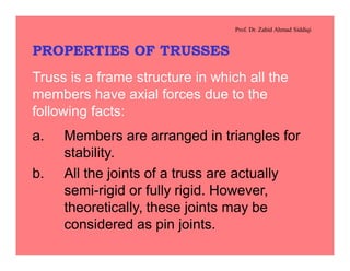
  • 1. Prof. Dr. Zahid Ahmad Siddiqi PROPERTIES OF TRUSSES Truss is a frame structure in which all the members have axial forces due to the following facts: a. Members are arranged in triangles for stability. b. All the joints of a truss are actually semi-rigid or fully rigid. However, theoretically, these joints may be considered as pin joints.
  • 2. Prof. Dr. Zahid Ahmad Siddiqi PANEL LOADS Concentrated load applied at the interior panel point of the truss in kN is called Panel Load (P). It is calculated by multiplying the roof load (load per unit area) by the horizontal area of roof contributing load to interior panel point of the truss, as described in Figures 7.6 and 7.7. It is separately calculated for dead, live and wind loads.
  • 3. Prof. Dr. Zahid Ahmad Siddiqi The truss is analyzed for unit gravity loads, unit wind on left side of truss and unit wind force on the right side of the truss. Principle of superposition is then used to calculate member forces due to actual loads. Load at interior panel point P = load intensity over horizontal plan area (w) ´ area supported by the panel point (p ´ s) = w ´ p ´ s
  • 4. Prof. Dr. Zahid Ahmad Siddiqi Load at exterior panel point = P / 2 s Area Contributing Load At One Interior Panel Point = p × s pp p/2p/2 s/2 s/2 a) Elevation of Truss b) Part – Plan of Truss Roof Figure 7.6. Area Exerting Load on an Interior Panel Point.
  • 5. Prof. Dr. Zahid Ahmad Siddiqi p = panel length in a horizontal plane s = center-to center spacing of trusses S Truss T-1 Truss T-2 p Figure 7.2. Isometric View of a Truss Roof.
  • 6. Prof. Dr. Zahid Ahmad Siddiqi Example 7.1: Find panel loads for the given truss data. Data: Angle of top chord, q = 30° Dead load of roofing = 160 N/m2 Insulation boards = 50 N/m2 Self weight of purlins = 100 N/m2 Self weight of bracing elements = 30 N/m2 Miscellaneous = 50 N/m2
  • 7. Prof. Dr. Zahid Ahmad Siddiqi Panel length, p = 2.5 m Span length of truss, l = 20 m Spacing of trusses, center-to-center, S = 5.5 m Solution: Total dead load except truss self weight = sum of given dead loads = 390 N/m2 Live load, from Reference-1, for q = 30o = 600 N/m2
  • 8. Prof. Dr. Zahid Ahmad Siddiqi Total gravity load, w = 390 + 600 = 990 N/m2 Using Thayer’s formula, self weight of truss = (0.37´20+1.7) @ 122 N/m2 5.5 990 Total dead load = 390 + 122 = 512 N/m2 Leeward wind pressure = 1250(– 0.7) = –875 N/m2
  • 9. Prof. Dr. Zahid Ahmad Siddiqi Windward wind pressure = 1250(– 0.9) = –1125 N/m2 and 1250(0.3) = 375 N/m2 Panel dead load, PD = w ´ p ´ S = 512 ´ 2.5 ´ 5.5 / 1000 = 7.04 kN Panel live load, PL = 600 ´ 2.5 ´ 5.5 / 1000 = 8.25 kN
  • 10. Prof. Dr. Zahid Ahmad Siddiqi The wind load is acting perpendicular to the inclined roof surface and hence actual inclined roof area is to be used to calculate the panel loads. This can be done by using the inclined panel length (p / cosq) in the expression for calculation of the panel loads. Panel wind load on leeward side, Pwl = (–875) (5.5) / 1000 = –13.89 kN (upward) ÷ ø ö ç è æ o 30cos 5.2
  • 11. Prof. Dr. Zahid Ahmad Siddiqi Panel wind load on windward side, Pww = (–1125) (5.5)/1000 = –17.86 kN ÷ ø ö ç è æ o 30cos 5.2 and = (375) (5.5)/1000 = 5.95 kN ÷ ø ö ç è æ o 30cos 5.2 TABLE OF FORCES In case only dead, live and wind loads are acting on a truss, following combinations may be investigated:
  • 12. Prof. Dr. Zahid Ahmad Siddiqi 1. 1.2D + 1.6Lr + 0.65W (Wind effect is small and may be ignored, especially if suction is present throughout) 2. 1.2D + 0.5 Lr + 1.3W a) Wind towards the Right b) Wind towards the Left 3. 0.9D + 1.3W a) Wind towards the Right b) Wind towards the Left
  • 13. Prof. Dr. Zahid Ahmad Siddiqi Member No. Unit gravity load member force Member force due to unit wind load on hinge side Member force due to unit wind load on roller side (1.2PD+ 1.6PL) ´Col.2 (1.2PD+0.5PL) ´Col.2 +1.3Pww ´ Col.3 +1.3Pwl ´ Col.4 (1.2PD+0.5PL) ´Col.2 +1.3Pww ´ Col.4 +1.3Pwl ´ Col.3 (1) (2) (3) (4) (5) (6) (7) Table 7.2. Sample Table of Forces.
  • 14. Prof. Dr. Zahid Ahmad Siddiqi 0.9PD´Col.2 +1.3Pww ´ Col.3 +1.3Pwl ´ Col.4 0.9PD´Col.2 +1.3Pww ´ Col.4 +1.3Pwl ´ Col.3 Maximum factored tension (Tu) Maximum factored Compression (Pu) Remarks (8) (9) (10) (11) (12)
  • 15. Prof. Dr. Zahid Ahmad Siddiqi PURLIN DESIGN General Notes A. Allowable stress design (ASD) or load and resistance factor design (LRFD) may be used for the design of a purlin. However, only ASD method is explained here in detail. Service loads and reduced material strengths are involved in allowable stress design. It is assumed that the roof sheathing provides the necessary lateral support to the purlin through J- bolts and the purlin behaves as a continuously braced beam.
  • 16. Prof. Dr. Zahid Ahmad Siddiqi Allowable bending strength, Mb = Fy Zx / Wb » Fy ´ 1.10 Sx / 1.67 = 0.66 Fy Sx Allowable bending stress, Fb = 0.66 Fy Allowable tensile stress, Ft = Fy / Wt = 0.60 Fy B. The dead plus live load (D + L) combination is used because it is proved to be critical for purlin and roof sheet design.
  • 17. Prof. Dr. Zahid Ahmad Siddiqi C. Dead load on purlin acts due to roofing, insulation and self-weight of the purlin. Insulation load is considered if it is directly attached or hanged from the sheet or the purlin. Approximately one-third or half of the miscellaneous load may also be included. D. Depth of section should not be lesser than 1/30 th of the purlin span to control deflections. dmin ³ S/30
  • 18. Prof. Dr. Zahid Ahmad Siddiqi E. Order of preference for member selection may generally be as under: i) Single angle section with no sag rod ii) Single angle section with one sag rod iii) Single angle section with two sag rod iv) C-section with no sag rod v) C-section with one sag rod vi) C-section with two sag rod vii) W or S-section with no sag rod viii) W or S-section with one sag rod ix) W or S-section with two sag rod
  • 19. Prof. Dr. Zahid Ahmad Siddiqi Z-section is behavior-wise the best section for a purlin. However, as it is not a hot-rolled section and is to be made by cold bending, it may not be readily available. In case the section modulus required for the first option is much greater than 230´103 mm3, the option of channel section may be selected directly. F. The width of angle section may not commonly exceed 102 mm. G. The roof load is converted into beam load per unit length by the formula given below:
  • 20. Prof. Dr. Zahid Ahmad Siddiqi Load per unit length = load per unit area of roof ´ purlin spacing Note:If the panel length is excessive and it is difficult to design the roofing, purlins are also placed in between the panel points reducing the purlin spacing and span for the roof sheet. This induces bending moment in the top chord of the truss, which must be checked as a beam column for such cases. H. Lateral component of loads at the top flange producing torsion should be considered separate from the self-weight of purlin not producing torsion.
  • 21. Prof. Dr. Zahid Ahmad Siddiqi Torque is Present No Torque Figure 7.8. Purlin Loads With And Without Torque. I. In place of using complicated formulas for torsion design, half strength in lateral direction (Sy/2 or Zy/2) is reserved for torsion and only the other half (Sy/2 or Zy/2) is used for lateral bending. No calculations for torsion are required afterwards.
  • 22. Prof. Dr. Zahid Ahmad Siddiqi J. Purlin is assumed to be simply supported on trusses, both for x and y direction bending. The bending moments may be calculated by using the typical bending moment diagrams given in Reference-1. K. Sag rod is considered as a lateral roller support for purlin with no effect on major axis bending (Figure 7.9). a) Major Axis Bending b) Minor Axis Bending Figure 7.9.Major Axis And Lateral Bending of a Purlin With Mid-Point Sag Rod.
  • 23. Prof. Dr. Zahid Ahmad Siddiqi L. Applied stress, fb = + stresses due to torque y y x x S M S M + For an ordinary beam (where only Mx is present), the section is selected on the basis of section modulus and not cross-sectional area as in tension and compression members. Sx = Mx / Fb However, in case of a purlin, two unknowns (Sx and Sy) occur in a single equation.
  • 24. Prof. Dr. Zahid Ahmad Siddiqi We cannot calculate Sx and Sy as such, making it necessary to use some simplifying assumption for the selection of the trial section. Once the trial section is selected, its stresses may easily be back checked to verify that they remain within the permissible range. Procedure For Purlin Design 1. wD (N/m) = (load of roofing + insulation +part of miscellaneous loads) ´ purlin pacing + (purlin self weight) ´ purlin spacing
  • 25. Prof. Dr. Zahid Ahmad Siddiqi wx wy q w Figure 7.10. Components of Load Acting On a Purlin. The two terms are kept separate as one is producing torque while the other is not.
  • 26. Prof. Dr. Zahid Ahmad Siddiqi 2. wL (N/m) = live load (N/m2) ´ purlin spacing Again, self weight of the purlin is kept as a separate entity. Calculate wx and wy by referring to Figure 7.10. Calculate maximum values of Mx and My by using bending moment diagrams for the given sag rod case. Further, calculate My for loads producing torsion and loads not producing torsion separately.
  • 27. Prof. Dr. Zahid Ahmad Siddiqi 6. For the selection of trial section, make the following approximation applicable only for this step. (My)ass = 0 (Mx)ass = Mx + 4 My for single unequal leg angle purlins (Mx)ass = Mx + 2 My for single equal leg angle purlins (Mx)ass = Mx + 15 My for C and W sections purlins
  • 28. Prof. Dr. Zahid Ahmad Siddiqi 7. Calculate the required elastic section modulus about the major axis according to the assumption of step number 6. (Sx)req = ( ) ( ) y assx b assx F M F M 66.0 = Select the section such that Sx » (Sx)req, d ³ S/30 and the preference of section is satisfied. 8. Actual bending stress is then evaluated by using the following expression: fb = (with torsion) + (no torsion) 2/y y x x S M S M + y y S M
  • 29. Prof. Dr. Zahid Ahmad Siddiqi Always consider magnitudes of Mx and My without their signs because each combination gives addition of stresses at some points within the section. 9. If the stress due to My is more than two times the stress due to Mx, revise the section by a) increasing the sag rods b) selecting section with bigger Sy / Sx ratio However, if sag rods are limited due to construction difficulties, the first option is not employed.
  • 30. Prof. Dr. Zahid Ahmad Siddiqi 10. If fb £ Fb OK otherwise, revise the section. 11. Check b/t for angles, bf / tf for channels and bf / 2tf for W-sections (called l-value). l £ lp OK otherwise, revise the section. For single angles, only shorter leg is in compression throughout and hence is to be used to check l value.
  • 31. Prof. Dr. Zahid Ahmad Siddiqi The value of lp for unstiffened elements is 10.8 and for stiffened elements is 31.6 for A36 steel. Any section meeting these requirements and continuously braced in lateral direction is called compact section. 12. Check self-weight of the purlin: Actual self-weight of purlin = weight of purlin section (kg/m) ´ 9.81 ´ number of purlin / span of the truss Provided self-weight £ 1.20 ´ assumed purlin weight OK
  • 32. Prof. Dr. Zahid Ahmad Siddiqi otherwise, revise purlin self-weight and all the calculations. Write the final selection using standard designation. Design the sag rod, if required. Design Of Sag Rod 1. Force in sag rod, F = force due to one purlin from Reference-1 ´ (no. of purlins on one side – 1)
  • 33. Prof. Dr. Zahid Ahmad Siddiqi 2. Component of tie rod force in the direction of sag rod direction should provide the required force F (Figure 7.11). R cos q = F Force in tie rod = R = F / cosq 3. Calculate required area of the sag and tie rods and select section.
  • 34. Prof. Dr. Zahid Ahmad Siddiqi Example 7.2: Design a channel section purlin with midpoint sag rod for the following data: Dead load of roofing = 160 N/m2 Insulation = 50 N/m2 Assumed self weight of purlin = 100 N/m2 (approximately 15% of the applied load) Live load = 590 N/m2 q = 30° p = 2.5 m S = 5.5 m
  • 35. Prof. Dr. Zahid Ahmad Siddiqi No. of truss panels = 8 Solution: wD = 210 ´ 2.5 + 100 ´ 2.5 = 525 + 250 N/m wL = 590 ´ 2.5 = 1475 N/m w = 2000 + 250 N/m Mx = S2 = = 7368 N-m 8 cosqw 2 5.5 8 30cos2250 ´ o
  • 36. Prof. Dr. Zahid Ahmad Siddiqi My = + = 945.3 + 118.2 N-m 2 5.5 32 30sin2000 ´ o 2 5.5 32 30sin250 ´ o (Mx)ass = Mx + 15 My = 23,320 N-m (Sx)req = = 141.3 ´ 103 mm3 25066.0 1000320,23 ´ ´ dmin = S / 30 = = 183 mm 30 10005.5 ´ Trial Section No. 1: C 230 ´ 19.9 Sx = 174 ´ 103 mm3 : Sy = 15.8 ´ 103 mm3
  • 37. Prof. Dr. Zahid Ahmad Siddiqi d > dmin OK fb = = 42.34 + 127.14 = 169.5 MPa > Fb (revise) 333 108.15 10002.118 10)2/8.15( 10003.945 10174 10007368 ´ ´ + ´ ´ + ´ ´ Note:The stress due to My is more than two times that due to Mx. The numerical values of stresses due to bending in the two directions also explain the importance of lateral bending compared with the major axis bending.
  • 38. Prof. Dr. Zahid Ahmad Siddiqi Smaller value of My divided by very less value of Sy/2 may give higher answer for the stresses. Trial Section No. 2: MC150´22.5 Sx = 136 ´ 103 mm3 Sy = 28.7 ´ 103 mm3 The depth of this section is less than the required minimum depth and hence it must be revised. Trial Section No. 3: C230´22 Sx = 185 ´ 103 mm3 Sy = 16.6 ´ 103 mm3 fb = 39.83 + 121.0 = 160.84 MPa < Fb OK
  • 39. Prof. Dr. Zahid Ahmad Siddiqi bf / tf = 63/10.5 = 6 < 10.8 OK Final Selection: C230 ´ 22 Check For Self Weight Actual self weight of purlin = @ 108 N/m2 < 1.20 ´ 100 N/m2 OK 20 1081.922 ´´ Design Of Sag Rod F = 5/8 w sinq ´ S ´ 4 = 5/8 ´ 2250 ´ sin 30° ´ 5.5 ´ 4 = 15,469 N
  • 40. Prof. Dr. Zahid Ahmad Siddiqi R = F / cosq = 15,469 / cos30° = 17,862 N Areq = = dreq = 12.31 mm Use 15 mm diameter steel bar as sag rods yF R 6.0 2 4 reqd p 2506.0 17862 ´
  • 41. Prof. Dr. Zahid Ahmad Siddiqi GALVANIZED IRON (G. I.) CORRUGATED ROOFING SHEETS Standard Designation: Nominal pitch in mm x Nominal depth in mm. Following two sheets are commonly used. 65 x 13 G. I. Corrugated Sheet. 75 x 20 G. I. Corrugated Sheet. The nomenclature for various dimensions is shown in Figures 7.13 and 7.14.
  • 42. Prof. Dr. Zahid Ahmad Siddiqi C S P D t W Figure 7.13. View of G. I. Corrugated Sheets Along the Corrugations. E E L Figure 7.14. View of G. I. Corrugated Sheets Perpendicular to Corrugations.
  • 43. Prof. Dr. Zahid Ahmad Siddiqi Symbol Description Sheet Designation 65 x 13 75 x 20 Pn Nominal pitch, mm 65 75 P Actual pitch, mm 66 73 Dn Nominal depth, mm 13 20 D Actual depth, mm 13 19 W Total width of one sheet, mm 700 700 S Side laps, mm 11/2 corrugations with fasteners placed at a maximum spacing of 300 mm in perpendicular direction. 105 115 C Cover (Effective width covered by one sheet), mm 595 585 Nc Number of corrugations in cover 9 8 E Minimum end lap, mm Fasteners are to be provided not less than at every third corrugation over each purlin. 200 200
  • 44. Prof. Dr. Zahid Ahmad Siddiqi t Thickness of sheet, mm Varies according to gage. Varies according to gage. L Length of one sheet, m 1.5m to 4.0m, 0.25m increments. Preferably should be close to multiples of horizontal panel length (p) divided by cosine of roof inclination (q) plus end lap (E). ( n p/cosq + E) ( n p/cosq + E) Fb Allowable working stress, MPa 0.60 Fy 0.60 Fy Da Maximum allowable deflection. span/90 span/90
  • 45. Prof. Dr. Zahid Ahmad Siddiqi US Gage Weight Thickness t Weight without laps Properties per meter of Corrugated width (Oz. per Sft.) (mm) (N/m2) A mm2 I (x 104 mm4) S (x 103 mm3) 12 70 2.753 236.7 2919 5.69 7.42 14 50 1.994 171.5 2098 4.03 5.48 16 40 1.613 139.0 1687 3.22 4.51 18 32 1.311 112.6 1361 2.58 3.70 20 24 1.006 86.7 1031 1.95 2.86 22 20 0.853 73.3 868 1.64 2.42
  • 46. Prof. Dr. Zahid Ahmad Siddiqi US Gage Weight Thickness t Weight without laps Properties per meter of Corrugated width (Oz. per Sft.) (mm) (N/m2) A mm2 I (x 104 mm4) S (x 103 mm3) 12 70 2.753 250.6 3107 14.45 13.28 14 50 1.994 181.6 2235 10.31 9.84 16 40 1.613 147.1 1797 8.26 8.01 18 32 1.311 119.3 1448 6.65 6.56 20 24 1.006 91.5 1099 5.04 5.03 22 20 0.853 77.6 923 4.23 4.26 24 16 0.701 63.7 747 3.43 3.47 26 12 0.551 50.3 576 2.64 2.69 28 10 0.475 43.1 487 2.23 2.29 29 9 0.437 39.8 445 2.03 2.09
  • 47. Prof. Dr. Zahid Ahmad Siddiqi Notes: U.S. Standard Gage is officially a weight gage, in Ounces per Sft. of flat sheet. The approximate thickness is calculated by using the steel density 7846 Kgs/m3 plus 2.5 percent allowance for average over-run in area and thickness. Smaller gage always means more sheet thickness.
  • 48. Prof. Dr. Zahid Ahmad Siddiqi Maximum actual deflection due to live udl: For simply supported sheet: Dmax. = 0.013 ´ wL p4 / EI For sheet with one end continuous considering some constraint at ends: Dmax. @ 0.001 ´ wL p4 / EI For sheet with one end continuous: Dmax. @ 0.0054 ´ wL p4 / EI Sheets per 100 m2 of inclined roof area are: N100 = ( ) ( )ELCECSLWL - @ +- 88 1010
  • 49. Prof. Dr. Zahid Ahmad Siddiqi DESIGN OF CORRUGATED SHEET 1. Use Reference-1 for the related definitions and data. Allowable stress design (ASD) is used here as for the purlin design. Dead plus live load combination seems to be critical for the sheet design and hence wind combinations are not considered. 2. End lap should be exactly on the purlin (Figures 7.13 and 7.14).
  • 50. Prof. Dr. Zahid Ahmad Siddiqi Incorrect Correct Rain Water Figure 7.14.Correct Placement of Overlap Within End Lap.
  • 51. Prof. Dr. Zahid Ahmad Siddiqi Accordingly, the length of sheet panel (L) is corresponding to 1,2 or 3 times the inclined panel length plus the required end lap. The resulting dimension may be rounded to upper 0.25 m length. If the required length of sheet corresponding to single panel length is more than 4.0 m or if the available section modulus does not satisfy the flexural criterion, extra purlins may be placed between the two panel points. If one purlin is used at center of a panel length, the span of the sheet reduces to p/2.
  • 52. Prof. Dr. Zahid Ahmad Siddiqi However, the top chord of the truss must be checked for the combined action of compression and bending moment. Similarly, purlin design must also be made using spacing of purlins equal to the modified c/c distance between the purlins. (a) End Lap Over Purlins (b) End Lap Within Purlins Correct Incorrect Figure 7.13.Correct Position of End Lap.
  • 53. Prof. Dr. Zahid Ahmad Siddiqi 3. Total load on the sheet = dead load of roofing + insulation + live load (N/m2). 4. Consider unit width of slab (1 m) and design this strip as a beam. 5. Load per unit length of roof strip, w (N/m), is calculated as follows: w = load per unit roof area ´ 1 m width = load per unit roof area, magnitude-wise only, in N/m units (only applicable for a roof and not for a beam)
  • 54. Prof. Dr. Zahid Ahmad Siddiqi 6. Assume the sheet to be simply supported over the purlins. Even if it is continuous, the maximum bending moment will nearly be the same. Mmax = (N – m) 8 2 pw´ 7. (Sx)req = yF M 6.0 1000max ´ Select gage of sheet from 1st column of the corresponding table in Reference-1 for properties of the corrugated sheets.
  • 55. Prof. Dr. Zahid Ahmad Siddiqi 8. Actual self weight of roofing = value from Col.4 of the properties table ´ 1.35 £ 1.2 ´ assumed weight OK If self-weight is significantly greater, revise the sheet as well as the purlin design. 9. Calculate the deflection due to live load (Dmax) and check against the allowable value (Da). Dmax < Da OK
  • 56. Prof. Dr. Zahid Ahmad Siddiqi 10. Calculate the number of sheet panels required for 100 m2 of roof area (N100) using the expression given in Reference – 1. It is better to use the actual length of the panel before rounding. 11. The total length of building may be represented by Nt ´ S, where Nt is the number of spaces between the trusses. The inclined roof area on one side, A = ´ Nt ´ S ( ) qcos ProjectionSheet2+l
  • 57. Prof. Dr. Zahid Ahmad Siddiqi Number of sheets on one side, N1 = A ´ (round to higher whole number) 100 100N Total number of sheets = 2 ´ N1 12. Decide spacing of bolts in end and side laps such that bolts are only applied at the crests. 13. Summarize the design results as under: Final Results For Corrugated Roof Sheet Design: 1. Gage of sheet
  • 58. Prof. Dr. Zahid Ahmad Siddiqi 2. Standard designation 3. Sheet panel size 4. Bolt spacing in the two directions 5. Number of sheets required