
Recommended
More Related Content
What's hot
What's hot (20)
Similar to Design of steel structure as per is 800(2007)
Similar to Design of steel structure as per is 800(2007) (20)
More from ahsanrabbani
More from ahsanrabbani (20)
Recently uploaded
Recently uploaded (20)
Design of steel structure as per is 800(2007)
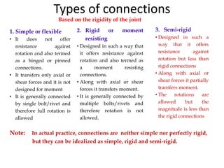
- 1. Types of connections Based on the rigidity of the joint 1. Simple or flexible • It does not offer resistance against rotation and also termed as a hinged or pinned connections. • It transfers only axial or shear forces and it is not designed for moment • It is generally connected by single bolt/rivet and therefore full rotation is allowed 3. Semi-rigid • Designed in such a way that it offers resistance against rotation but less than rigid connections • Along with axial or shear forces it partially transfers moment. • The rotations are allowed but the magnitude is less than the rigid connections 2. Rigid or moment resisting • Designed in such a way that it offers resistance against rotation and also termed as a moment resisting connections. • Along with axial or shear forces it transfers moment. • It is generally connected by multiple bolts/rivets and therefore rotation is not allowed. Note: In actual practice, connections are neither simple nor perfectly rigid, but they can be idealized as simple, rigid and semi-rigid.
- 2. Types of connections Based on the internal forces transferred 2. Axially loaded connections •These are assumed to be hinged •Ideally, members should be connected by one bolt. •If, connected by two or more bolts or welds, results in to the development of small partial fixity which can be ignored. 3. Eccentrically loaded connections: I. Connections in which moment acting in the plane of joint (i.e. joint subjected to shear force and torsional moment) II. Connections in which moment acting perpendicular to the plane of joint (i.e. joint subjected to shear force and bending moment) 1. Beam end connections: I. Framed connections: Web of the beam is connected directly to the column or another beam II. Seated connections: a) Stiffened b) Unstiffened flange of the beam is connected to column with the help of seating arrangement Answer 1. Simple or flexible Question: In which category it will fall in previous classification? Answer : 1. Simple or flexible Truss member joints Question: Give category and an example of this classification? Question: In which category it will fall in previous classification? Answer : 2. Rigid or moment resisting
- 3. Eccentric Connections Applied load does not pass through C.G of connections Fig 2
- 4. Forces On Bracket Type 1
- 5. Bolted Bracket Connections Type 2
- 6. Welded Bracket Connections Type 1
- 7. Welded Bracket Connections Type 2
- 8. • Designed more conservatively than members because they are more complex to analyse and discrepancy between analysis and design is large • In case of overloading, failure in member is preferred to failure in connection • Connections account for more than half the cost of structural steel work • Connection design has influence over member design • Similar to members, connections are also classified as idealised types effected through rivets, bolts or weld • Codal Provisions Design considerations for connections
- 9. Types of Fasteners Rivets: • Use of rivets is becoming obsolete as it requires preheating, skilled supervision, more labour and riveting equipment. • Therefore, emphasis is given on design of bolts and design of rivets is similar to design of bolts.
- 10. Bolts Black Bolts: (IS:1363 -Part 1, 2 and 3, – 2002) • made up of mild steel bars with square of hexagonal head • commonly used and less expensive. • commonly used for light structures • not recommended for connections subjected to impact, fatigue and dynamic loads. Types of Fasteners Strength of black bolt Bolt Grade: Grade 4.6 :- fu = 400 N/mm2 and fy = 0.6*400 = 240 N/mm2
- 11. Bolts High strength bolts: They are made up of bars of medium carbon steel bars The bolts of property class 8.8 and 10.9 are commonly used in steel construction and identified by ‘8.8S’ and ‘10.9S’ marking on the bolt head. Suffix ‘S’ denotes high strength bolt. grade 4.6 to 8.8 Types of Fasteners
- 12. Bolts High strength friction grip (HSFG) bolts: They conform to IS:3757-1985 These are the bolts with induced initial tension. They do not allow slip between the connected members Due to the high strength, no. of bolts required are less and size of gusset plate required is also less. grades from 8.8 to 10.9 Types of Fasteners
- 13. • Grip is the distance from behind the bolt head to the back of the nut or washer It is the sum of the thicknesses of all the parts being joined exclusive of washers • Thread length is the threaded portion of the bolt • Bolt length is the distance from behind the bolt head to the end of the bolt Parts of the Bolt Assembly Head Shank Washer NutWasher Face Grip Thread Length Parts of the Bolt Assembly
- 14. • The bolting operation is very silent. • Bolting is cold process hence there is no risk of fire. • Bolting operation is more quicker than riveting. • Less man power is required in making the connections. • If subjected to vibratory loads, results in reduction in strength get loosened. • Unfinished bolts have lesser strength because of non uniform diameter. Advantages Disadvantages Types of Fasteners
- 15. Essential background • Table 1 Tensile Properties of Structural Steel Products, IS 800:2007, (Clauses 1.3.113, 1.3.119 and 2.2.4.2) 240 320
- 16. Essential background • Table 5 Partial Safety Factor for Materials, m • (Clause 5.4. 1)
- 17. Shear Connections a) Lap Connection b) Butt Connection (a) (b) Tension Connection Tension plus Shear Connection Some typical arrangement Single shear Double shear Classification based on type of force in the bolts
- 18. Bolt Shear Transfer – Free Body Diagram (a) Bearing Connection (b) Friction Connection T Frictional Force T Clamping Force, PO Bearing stresses Tension in bolt T T T Clamping Force, PO Force Transfer Mechanism
- 19. Failure Of Connections (a) Shearing of Bolts (b) Bearing on Bolts (c) Bearing on Plates Zone of plastification Shear Connections with Bearing Bolts Bearing Yield Bearing Fracture Bearing Fracture Bearing Yield 19
- 20. • In a bearing joint the connected elements are assumed to slip into bearing against the body of the bolt • If the joint is designed as a bearing joint the load is transferred through bearing whether the bolt is installed snug-tight or pretensioned Bearing Joints
- 21. • The shear plane is the plane between two or more pieces under load where the pieces tend to move parallel from each other, but in opposite directions • The threads of a bolt may either be included in the shear plane or excluded from the shear plane • The capacity of a bolt is greater with the threads excluded from the shear plane Threads in the Shear Plane Threads Included In The Shear Plane Threads Excluded From The Shear Plane
- 22. Codal Requirements of Bolted Connections Clearance of fastener holes (10.2.1): Sr. No. Nominal size of Fastener in mm (d) Standard clearance in diameter and width of slot in mm Oversize clearance in diameter in mm Clearance in length of the slot in mm Short slot Long slot 1 12-14 1.0 3.0 4.0 2.5d 2 16-22 2.0 4.0 6.0 2.5d 3 24 2.0 6.0 8.0 2.5d 4 >24 3.0 8.0 10.0 2.5d Minimum Spacing (10.2.2): Minimum pitch = 2.5d, Where d = nominal diameter of the fastener
- 23. Maximum Spacing (10.2.3): • In general, max. pitch = 32t or 300 mm whichever is less • For tension member, maximum pitch = 16t or 200 mm whichever is less • For compression member, maximum pitch = 12t or 200 mm whichever is less • For consecutive fasteners in a line adjacent and parallel to an edge of an outside plate • maximum gauge = 100+4t or 200 mm whichever is less • where t = thickness of thinner plate in connection Codal Requirements of Bolted Connections
- 24. Edge and end distances (10.2.4): Minimum edge and end distances = 1.5 times the hole diameter in case of rolled, machine-flame cut, sawn and planed edges measured from centre of any hole to the nearest edge of a plate. Minimum edge and end distances = 1.7 times the hole diameter in case of sheared or hand-flame cut edges Codal Requirements of Bolted Connections
- 25. Effective areas of bolts (10.3.1) For shear plane in plain part of the bolt, effective areas of bolt is given by diameter of bolt at shank. (i.e𝐴 𝑒 = 𝐴 𝑠𝑏 = 𝜋𝑑2 4 ) For shear plane in threaded part of the bolt, effective areas of bolt is given by diameter of bolt at root of the thread (i.e𝐴 𝑒 = 𝐴 𝑛𝑏 = 𝜋𝑑 𝑛 2 4 ) In absence of data, 𝐴 𝑛𝑏 = 0.78 𝐴 𝑠𝑏 Codal Requirements of Bolted Connections
- 26. Shear capacity of the bolt (10.3.3): The nominal shear capacity of the bolt is given by: 𝑉𝑛𝑠𝑏 = 𝑓 𝑢𝑏 3 (𝑛 𝑛. 𝐴 𝑛𝑏 + 𝑛 𝑠. 𝐴 𝑠𝑏) where Asb = Nominal plain shank area of the bolt An b = Net shear area of bolt at threads corresponding to the root diameter of the thread fub = Ultimate tensile strength of the bolt nn = No. of shear planes with threads intercepting the shear plane ns = No. of shear planes without threads intercepting the shear plane Design Strength of Bolt Codal Requirements of Bolted Connections
- 27. Shear capacity of the bolt (10.3.3): The design shear capacity of the bolt is given by: 𝑉𝑑𝑠𝑏 = 𝑉𝑛𝑠𝑏 𝛾 𝑚𝑏 = 𝑓𝑢 1.25 3 𝑛 𝑛. 𝐴 𝑛𝑏 + 𝑛 𝑠. 𝐴 𝑠𝑏 = 0.462𝑓𝑢 𝑛 𝑛. 𝐴 𝑛𝑏 + 𝑛 𝑠. 𝐴 𝑠𝑏 Design Strength of Bolt Codal Requirements of Bolted Connections
- 28. Bearing capacity of the bolt (10.3.4) The nominal bearing capacity of the bolt on any plate is given by: 𝑉𝑛𝑝𝑏 = 2.5 𝑘 𝑏 𝑑 𝑡 𝑓𝑢where kb = e, p = End and pitch distances of fasteners along bearing direction do = Diameter of bolt hole fub,fu = Ultimate tensile strength of the bolt & plate respectively t = Thickness of the connected plates experiencing bearing stress in the same direction Design Strength of Bolt Codal Requirements of Bolted Connections
- 29. Design Strength of Bolt Codal Requirements of Bolted Connections
- 30. Design Strength of Bolt Design strength of the bolt (10.3.2): The design strength of the bolt, Vdb : Shall be taken as the smaller of the value as governed by, 1. Shear, Vdsb and 2. Bearing, Vdpb. Codal Requirements of Bolted Connections
- 31. Design Strength of Bolt Reduction in design strength of the bolt: Long joints (10.3.3.1): When the length of the joint, lj containing more than two bolts (i.e. the distance between the first and last rows of bolts in the joint measured in the direction of the load) exceeds 15d in the direction of load, the nominal shear capacity Vdb shall be reduced by the factor βlj given by 𝛽𝑙𝑗 = 1.075 − 𝑙𝑗 200𝑑 𝑏𝑢𝑡 0.75 ≤ 𝛽𝑙𝑗 ≤ 1.0 Codal Requirements of Bolted Connections
- 32. Design Strength of Bolt Reduction in design strength of the bolt: Large grip lengths (10.3.3.2): When the grip length, lg (equal to the total thickness of connected plates) exceeds the connected plates) exceeds 5 times the diameter, d of the bolts, the design shear capacity shall be reduced by a factor βlg given by 𝛽𝑙𝑔 = 8𝑑 3𝑑 + 𝑙 𝑔 𝑏𝑢𝑡 𝛽𝑙𝑔 ≤ 𝛽𝑙𝑗 𝑎𝑛𝑑 𝑙 𝑔 ≤ 8𝑑 Codal Requirements of Bolted Connections
- 33. Design Strength of Bolt Reduction in design strength of the bolt: Packing plates (10.3.3.3): The design shear capacity of bolts carrying shear through a packing plate in excess of 6 mm shall be decreased by a factor βpk given by 𝛽 𝑝𝑘 = 1 − 0.0125 𝑡 𝑝𝑘 Where tpk = thickness of the thicker packing, in mm. Codal Requirements of Bolted Connections
- 34. Design Strength of Bolt Tension capacity of the bolt (10.3.5): The nominal tension capacity of the bolt is given by: 𝑇𝑛𝑏 = 0.9 𝑓𝑢𝑏 𝐴 𝑛 ≤ 𝑓𝑦𝑏 𝐴 𝑠𝑏 𝛾 𝑚𝑏 𝛾 𝑚𝑜 The design tension capacity of the bolt is given by: 𝑇𝑑𝑏 = 𝑇𝑛𝑏 𝛾 𝑚𝑏 Where fub = Ultimate tensile strength of the bolt An = Net tensile area of the bolt Asb = Shank area of the bolt Codal Requirements of Bolted Connections
- 35. Example 1 Q. Determine the bolt value of 16 mm diameter bolt 4.6 grade connecting 8 mm thick plate of 410 grade in (i) Single shear and (ii) Double shear For 4.6 grade bolt, fub = 400 Mpa, Asb = 201 mm2 fyb = 60% of fub Anb = 0.78 x Asb = 0.6x400 = 156 mm2 = 240 Mpa
- 36. Example 1 𝑉𝑑𝑠𝑏 = 0.462𝑓𝑢 𝑛 𝑛. 𝐴 𝑛𝑏 + 𝑛 𝑠. 𝐴 𝑠𝑏 𝑉𝑑𝑝𝑏 = 2.0 𝑘 𝑏 𝑑 𝑡 𝑓𝑢 = 0.462x400x(1x156)x10-3 = 2x1x16x8x410x10-3 = 28.8 kN in single shear = 104.96 kN in bearing = 57.6 kN in double shear Bolt value = 28.8 kN in single shear = 57.6 kN in double shear
- 37. Example 2 Q. Design a lap joint between the plates of size 80x10 mm and 80x8 mm thick so as to transfer a factored load of 80 kN using single row of bolts of grade 4.6 and grade 410 plate For 4.6 grade bolt of 16 mm diameter, fub = 400 Mpa, d = 16 mm Asb = 201 mm2 fyb = 60% of fub d0 = 18 mm Anb = 0.78 x Asb = 0.6x400 e = 1.7x18 = 30.6 mm = 156 mm2 = 240 Mpa Say 35 mm p = 2.5x16 = 40 mm
- 38. Example 2 𝑉𝑑𝑠𝑏 = 0.462𝑓𝑢 𝑛 𝑛. 𝐴 𝑛𝑏 + 𝑛 𝑠. 𝐴 𝑠𝑏 = 0.462x400x(1x156)x10-3 = 28.8 kN in single shear 𝑒 3𝑑 𝑜 = 35 3𝑥18 = 0.65, 𝑝 3𝑑 𝑜 − 0.25 = 40 3𝑥18 − 0.25 = 0.49, 𝑓𝑢𝑏 𝑓𝑢 = 400 410 = 0.98 Kb = Smaller of 𝑒 3𝑑 𝑜 , 𝑝 3𝑑 𝑜 − 0.25, 𝑓 𝑢𝑏 𝑓𝑢 𝑎𝑛𝑑 1.0 Kb = 0.49
- 39. Example 2 𝑉𝑑𝑝𝑏 = 2.0 𝑘 𝑏 𝑑 𝑡 𝑓𝑢 = 2x0.49x16x8x410x10-3 = 51.43 kN in bearing Bolt value = 28.8 kN No. of Bolts = 80 28.8 = 2.8 𝑠𝑎𝑦 3 𝑛𝑜𝑠. Check: Lj = 2x40 = 80 mm < (15d = 15x16 = 240 mm) Therefore no reduction in strength as per long joint Lg = 10+8 = 18 mm < (5d = 5x16 = 80 mm) Therefore no reduction in strength as per large grip No reduction for packing plate.
- 40. Example 3 Q. A bridge truss diagonal carries an axial pull of 250 kN. Two plates of 200x10 mm and 200x16 mm are required to be joined together by butt joint. Design suitable double cover butt joint with bolts of grade 4.6 and grade 410 plate For 4.6 grade bolt of 20 mm diameter, fub = 400 Mpa, d = 20 mm Asb = 314 mm2 fyb = 60% of fub d0 = 22 mm Anb = 0.78 x Asb = 0.6x400 e = 1.7x22 = 37.4 mm = 245 mm2 = 240 Mpa Say 40 mm p = 2.5x20 = 50 mm
- 41. Example 3 200x16 plate 200x10 plate 250 kN 250 kN 35 40 4035 35 Packing plate 6 thick Cover plates 8 thick
- 42. Example 3 𝑉𝑑𝑠𝑏 = 0.462𝑓𝑢 𝑛 𝑛. 𝐴 𝑛𝑏 + 𝑛 𝑠. 𝐴 𝑠𝑏 = 0.462x400x(2x245)x10-3 = 90.55 kN in single shear 𝑒 3𝑑 𝑜 = 40 3𝑥22 = 0.61, 𝑝 3𝑑 𝑜 − 0.25 = 50 3𝑥20 − 0.25 = 0.58, 𝑓𝑢𝑏 𝑓𝑢 = 400 410 = 0.98 Kb = Smaller of 𝑒 3𝑑 𝑜 , 𝑝 3𝑑 𝑜 − 0.25, 𝑓 𝑢𝑏 𝑓𝑢 𝑎𝑛𝑑 1.0 Kb = 0.58
- 43. Example 3 For connection on 16 mm plate𝑉𝑑𝑝𝑏 = 2.0 𝑘 𝑏 𝑑 𝑡 𝑓𝑢 = 2x0.58x16x20x410x10-3 = 152.19 kN in bearing on 16mm Bolt value = 90.55 kN No. of Bolts = 250 90.55 = 2.76 𝑠𝑎𝑦 3 𝑛𝑜𝑠. Check: Lj = 0 < (15d = 15x20 = 300 mm) Therefore no reduction in strength as per long joint Lg = 20+8+8 = 36 mm < (5d = 5x20 = 100 mm) Therefore no reduction in strength as per large grip No reduction for packing plate.
- 44. Example 3 For connection on 10 mm plate𝑉𝑑𝑝𝑏 = 2.0 𝑘 𝑏 𝑑 𝑡 𝑓𝑢 = 2x0.58x20x10x410x10-3 = 95.12 kN in bearing on 10mm For packing plate 𝛽 𝑝𝑘 = 1 − 0.0125 𝑡 𝑝𝑘 = 1-0.0125x10 = 0.875 Bolt value = 0.875x90.55 = 79.23 kN No. of Bolts = 250 79.23 = 3.15 𝑠𝑎𝑦 4 𝑛𝑜𝑠. Check: Lj = 50 < (15d = 15x20 = 300 mm) Therefore no reduction in strength as per long joint Lg = 20+8+8 = 36 mm < (5d = 5x20 = 100 mm) Therefore no reduction in strength as per large grip
- 45. Example 4 Q. Figure shows the joint in the bottom chord member of a truss, design the connection using M16 black bolt of property class 4.6 and grade 410 steel sections. 135 kN (ISA75X75X8) 75 kN (ISA50X50X8) 370 kN (2-ISA100X100X8) 250 kN (2-ISA100X100X8) O B C DA
- 46. Example 4 For 4.6 grade M16 bolt, fub = 400 Mpa, d = 16 mm Asb = 201 mm2 fyb = 60% of fub d0 = 18 mm Anb = 0.78 x Asb = 0.6x400 e = 1.7x18 = 30.6 mm = 156 mm2 = 240 Mpa Say 35 mm p = 2.5x16 = 40 mm 𝑉𝑑𝑠𝑏 = 0.462𝑓𝑢 𝑛 𝑛. 𝐴 𝑛𝑏 + 𝑛 𝑠. 𝐴 𝑠𝑏 = 0.462x400x(1x156)x10-3 = 28.8 kN in single shear = 57.6 kN in double shear
- 47. Example 4 Let gusset plate be 10 mm thick 𝑒 3𝑑 𝑜 = 35 3𝑥18 = 0.65, 𝑝 3𝑑 𝑜 − 0.25 = 40 3𝑥18 − 0.25 = 0.49, 𝑓𝑢𝑏 𝑓𝑢 = 400 410 = 0.98 Kb = Smaller of 𝑒 3𝑑 𝑜 , 𝑝 3𝑑 𝑜 − 0.25, 𝑓 𝑢𝑏 𝑓𝑢 𝑎𝑛𝑑 1.0 Kb = 0.49
- 48. Example 4 For connection on 8 mm plate𝑉𝑑𝑝𝑏 = 2.0 𝑘 𝑏 𝑑 𝑡 𝑓𝑢 = 2x0.49x16x8x410x10-3 = 51.43 kN in bearing on 8mm For connection on 10 mm plate𝑉𝑑𝑝𝑏 = 2.0 𝑘 𝑏 𝑑 𝑡 𝑓𝑢 = 2x0.49x16x10x410x10-3 = 64.29 kN in bearing on 8mm For single angle members, bolt value = 28.8 kN For single angle members, bolt value = 57.6 kN
- 49. Example 4 For member OB No. of Bolts = 75 28.8 = 2.60 𝑠𝑎𝑦 3 𝑛𝑜𝑠. Check: Lj = 80 < (15d = 15x16 = 240 mm) Therefore no reduction in strength as per long joint Lg = 10+8 = 18 mm < (5d = 5x16 = 80 mm) Therefore no reduction in strength as per large grip No reduction for packing plate.
- 50. Example 4 For member OC No. of Bolts = 135 28.8 = 4.69 𝑠𝑎𝑦 5 𝑛𝑜𝑠. Check: Lj = 160 < (15d = 15x16 = 240 mm) Therefore no reduction in strength as per long joint Lg = 10+8 = 18 mm < (5d = 5x16 = 80 mm) Therefore no reduction in strength as per large grip No reduction for packing plate.
- 51. Example 4 For member OA if OA and OD are discontinuous at joint No. of Bolts = 370 57.6 = 6.42 𝑠𝑎𝑦 7 𝑛𝑜𝑠. Check: Lj = 240 < (15d = 15x16 = 240 mm) Therefore no reduction in strength as per long joint Lg = 10+20 = 30 mm < (5d = 5x16 = 80 mm) Therefore no reduction in strength as per large grip No reduction for packing plate.
- 52. Example 4 For member OD if OA and OD are discontinuous at joint No. of Bolts = 250 57.6 = 4.34 𝑠𝑎𝑦 5 𝑛𝑜𝑠. Check: Lj = 160 < (15d = 15x16 = 240 mm) Therefore no reduction in strength as per long joint Lg = 10+20 = 30 mm < (5d = 5x16 = 80 mm) Therefore no reduction in strength as per large grip No reduction for packing plate.
- 53. Example 4 For member OA and OD if they are continuous at joint No. of Bolts = 370−250 57.6 = 2.08 𝑠𝑎𝑦 3 𝑛𝑜𝑠. Check: Lj = 80 < (15d = 15x16 = 240 mm) Therefore no reduction in strength as per long joint Lg = 10+20 = 30 mm < (5d = 5x16 = 80 mm) Therefore no reduction in strength as per large grip No reduction for packing plate.
- 55. Efficient and direct way of connecting is by welding Metallurgical bond by heat or pressure or both • Types of weld Gas welding - Oxyacetelene welding , simple , slow, repair and maintenance work Arc welding - All structural welding Electric arc by use of electric energy Types of Fasteners Welds: They conform to IS:816-1969, IS:9595-1996.
- 56. Classification of welds Types of Fasteners A Ends shall be semi circular A Section A-A (c) Slot weld (a) Groove welds (b) Fillet welds AA Section A-A (d) Plug weld
- 57. • Fillet welds: Advantages Ease of fabrication and adaptability Less precision No special edge preparation Throat of a weld Concave and convex surfaces Types of Fasteners Theoretical throat (t=0.707s) t Te s Root of weld Face of weld Weld and leg size
- 58. Requirements of Welded Connections Size of the weld – S (10.5.2): Minimum size of weld =3 mm Depending on the thickness of the thicker plate to be connected, minimum size of weld should be Thickness of thicker plate Minimum size of weld in mm Upto 10 mm 3 11 to 20 mm 5 21 to 32 mm 6 33 to 50 mm 10 - 8 (first run)
- 59. Requirements of Welded Connections General (10.5.1): • Minimum end return ≥2S • (important for sides carrying bending tension) • For lap joint Minimum lap ≥4t_ or 40 mm whichever is greater • Single fillet weld is not subjected to moment about its longitudinal axis
- 60. Requirements of Welded Connections Size of the weld – S (10.5.2): If minimum size of weld is greater than the thickness of thinner member, minimum size of weld should be thickness of thinner member Size of butt weld is specified by effective throat thickness
- 61. Requirements of Welded Connections Effective throat thickness - t (10.5.3): For fillet weld t ≥ 3 mm t ≥ 0.7x tmin of member For stress calculation in fillet weld, t = K. Angle between fusion faces in degrees 60- 90 91- 100 101- 106 107- 113 114- 120 K 0.70 0.65 0.60 0.55 0.50
- 62. Requirements of Welded Connections Effective throat thickness - t (10.5.3): For full penetration butt weld, t = tmin of connected members For incomplete penetration butt weld t = minimum thickness of weld metal common to the parts joined.
- 63. Requirements of Welded Connections Effective length of weld - lw (10.5.4): For fillet weld, actual length of weld = lw+2S ≥4S For butt weld, lw ≥4S Intermittent welds (10.5.5): For fillet weld, lw ≥ 4S or minimum of 40 mm Clear spacing between weld lengths ≤12t or maximum of 200 mm for compression member ≤16t or maximum of 200 mm for tension member Where t is the thickness of the thinner part.
- 64. Requirements of Welded Connections Intermittent welds (10.5.5): For butt weld, lw ≥4S or minimum of 40 mm Clear spacing between weld lengths ≤16 times the thickness of the thinner member Note: Intermittent welds shall not be used for members subjected to dynamic loads, and reversal of stresses.
- 65. Design Strength of Weld Design stresses in welds (10.5.7): Fillet welds Design strength of fillet weld 𝑓𝑤𝑑 = 𝑓 𝑤𝑛 𝛾 𝑚𝑤 Where 𝑓𝑤𝑛 = 𝑓𝑢 √3 γmw = 1.25 and 1.5 for shop weld and field weld respectively Butt welds Stresses in welds are same as that of parent metal
- 66. Design Strength of Weld Reduction Factor When the length of the welded joint, lj is greater than 150 tt, the design capacity of weld fwd shall be reduced by the factor 𝛽𝑙𝑗 = 1.2 − 0.2𝑙𝑗 150𝑡𝑡 ≤ 1.0 Where lj = length of the joint in the direction of the force transfer tt = throat size of the weld.
- 67. Example 5 Q. An ISA 125x95x10 carries a factored tensile force of 420 kN and it is connected by its longer leg to 8 mm thick gusset plate. Design a suitable welded joint using (i) 6 mm fillet weld on toe and heel (ii) 6 mm fillet weld on toe heel and at end also (iii) 6 mm fillet weld on toe and 8 mm fillet weld at heel and end.
- 68. Example 5 (i) 6 mm fillet weld on toe and heel Let Pu1 and Pu2 be forces acting on toe and heel P is acting at centroid of angle section i. e. at 38.9 mm from heel. Taking moment of forces about heel Pu1 = 420𝑥38.9 125 = 130.7 𝑘𝑁 Pu2 = 420 − 130.7 = 289.3 𝑘𝑁
- 69. Example 5 (i) 6 mm fillet weld on toe and heel Smin = 3 mm < 6 mm Smax = 3 4 𝑥10 = 7.5 𝑚𝑚> 6 mm Therefore we can use 6 mm weld i.e. S = 6 mm Throat thickness = 0.7x6 = 4.2 mm Strength of weld, 𝑓𝑤𝑑 = 𝑓 𝑤𝑛 𝛾 𝑚𝑤 Where 𝑓𝑤𝑛 = 𝑓𝑢 √3 = 410 √3 = 236 Mpa 𝑓𝑤𝑑 = 𝑓 𝑤𝑛 𝛾 𝑚𝑤 = 236 1.25 = 189 MPa
- 70. Example 5 (i) 6 mm fillet weld on toe and heel Strength of weld per mm length = 𝑓𝑤𝑑 𝑥 𝑡ℎ𝑟𝑜𝑎𝑡 𝑡ℎ𝑖𝑐𝑘𝑛𝑒𝑠𝑠 = 189 x 4.2 = 795 N/mm Length of weld required on heel = 𝑃 𝑢2 795 = 289300 795 = 363 𝑚𝑚 𝑠𝑎𝑦 370 𝑚𝑚 Length of weld required on toe = 𝑃 𝑢1 795 = 130700 795 = 165 𝑚𝑚 𝑠𝑎𝑦 170 𝑚𝑚
- 71. Example 5 (ii) 6 mm fillet weld on toe, heel and end Let Pu1 Pu2 and Pu3 be forces acting on toe, heel and end P is acting at centroid of angle section i. e. at 38.9 mm from heel. Smin = 3 mm < 6 mm Smax = 3 4 𝑥10 = 7.5 𝑚𝑚> 6 mm Therefore we can use 6 mm weld i.e. S = 6 mm
- 72. Example 5
- 73. Example 5 (ii) 6 mm fillet weld on toe , heel and end Strength of weld per mm length = 𝑓𝑤𝑑 𝑥 𝑡ℎ𝑟𝑜𝑎𝑡 𝑡ℎ𝑖𝑐𝑘𝑛𝑒𝑠𝑠 = 189 x 4.2 = 795 N/mm Length of weld required on heel = 𝑃 𝑢2 795 = 239700 795 = 302 𝑚𝑚 𝑠𝑎𝑦 310 𝑚𝑚 Length of weld required on toe = 𝑃 𝑢1 795 = 81100 795 = 102 𝑚𝑚 𝑠𝑎𝑦 110 𝑚𝑚
- 74. Example 5 (iii) 6 mm fillet weld on toe and 8 mm on heel and end Let Pu1 Pu2 and Pu3 be forces acting on toe, heel and end P is acting at centroid of angle section i. e. at 38.9 mm from heel. On heel and toe, S = 8 mm Throat thickness = 0.7x8 = 5.6 mm Strength of weld, 𝑓𝑤𝑑 = 𝑓 𝑤𝑛 𝛾 𝑚𝑤 Where 𝑓𝑤𝑛 = 𝑓𝑢 √3 = 410 √3 = 236 MPa 𝑓𝑤𝑑 = 𝑓 𝑤𝑛 𝛾 𝑚𝑤 = 236 1.25 = 189 MPa Pu3 = fwd x 0.7S x lw= 189 x 5.6 x 125 = 132300 N = 132.3 kN
- 75. Example 5(iii) 6 mm fillet weld on toe and 8 mm on heel and end Taking moment of forces about heel Pu1 = 420𝑥38.9−132.3𝑥 125 2 125 = 64.6 𝑘𝑁Pu2 = 420 − 132.3 − 64.6 = 223.1 𝑘𝑁 Strength of weld per mm length on heel = 𝑓𝑤𝑑 𝑥 𝑡ℎ𝑟𝑜𝑎𝑡 𝑡ℎ𝑖𝑐𝑘𝑛𝑒𝑠𝑠 = 189 x 5.6 = 1058 N/mm Length of weld required on heel = 𝑃 𝑢2 795 = 223100 1058 = 211 𝑚𝑚 say 220 mm
- 76. Example 5 (iii) 6 mm fillet weld on toe and 8 mm on heel and end Strength of weld per mm length on toe = 𝑓𝑤𝑑 𝑥 𝑡ℎ𝑟𝑜𝑎𝑡 𝑡ℎ𝑖𝑐𝑘𝑛𝑒𝑠𝑠 = 189 x 4.2 = 795 N/mm Length of weld required on toe = 𝑃 𝑢1 795 = 64600 795 = 82 𝑚𝑚 say 90 mm
- 78. When torque or twisting moment is in the plane of onnection the connections may be termed as a bracket connection type-I This situation occurs when line of action of load is in the plane of bolted connection and centre of gravity of connection is the centre of rotation Forces on bolts bracket connection type-I Bracket Connection - Type -1:
- 79. The forces due to direct shear F1 and due to torque F2 are given by,
- 80. Examples: 6 Determine safe load P that can be carried by a bolted bracket connection as shown in Fig. The bolts are 20 mm diameter of grade 4.6. The thickness of the flange of l-section is 10.6 mm and that of bracket plate is 12 mm.
- 83. Design a bracket connection using 4.6 grade black bolt of suitable size to transmit a factored load of 135 kN (applied on a 12 mm thick bracket plate) to the flange of a column ISHB 225. The load eccentricity is 200 mm measured from the column axis as shown in figure. (MU 2014, 10 Mark) Solution (ii) Design of bolts : Using M20 black bolts of grade 4.6 Strength of bolt: (cl. 10.3.2, IS 800-2007) Fub = 400N/mm2 d = 20 mm do = 20 + 2 = 22 mm emin = 1.5 do = 1.5x22 = 33 mm, Pmin = 2.5 xd = 2.5x20 = 50mm = 60 mm (i) Load P for which bracket designed : The design load P is always considered 50% of the reaction transferred by the beam. But in this case P is directly given. P = 135 kN Examples: 7
- 85. Detailing
- 86. When the bending moment of eccentric force P is in a plane perpendicular to the plane of connection then the bracket connection is termed as bracket connection type-II Forces on bolts bracket connection type-II Bracket Connection Type-ll :
- 87. Determine P. Use 2ISA 100 x 100 x 12 mm angle. Use 20 mm dia bolts for connection. The thickness of bracket plate is 16 mm as shown in Fig. (MU 2013, 10 Mark) Examples: 7
- 88. Design of Welded Bracket Connection : Plate is conA10 mm thick bracket nected with the flange of an ISHB 250 @ 51 kg/m column using 8 mm size of shop weld as shown in Figure Find the maximum value of load P that can safely be applied on the bracket. Examples: 8
- 92. A bracket plate is welded to the flange of a column section ISHB 300@ 618 N/m as shown in Fig. Calculate the size of weld required to support a factored load 220 kN. Assume shop welding. Examples: 9
Editor's Notes
- © IIT Madras, SERC Madras, Anna Univ., INSDAG Calcutta