

Recommended
More Related Content
What's hot
What's hot (20)
Similar to DESIGN OF RAFT FOUNDATION
Similar to DESIGN OF RAFT FOUNDATION (20)
More from Shahzad Ali
Recently uploaded
Recently uploaded (20)
DESIGN OF RAFT FOUNDATION
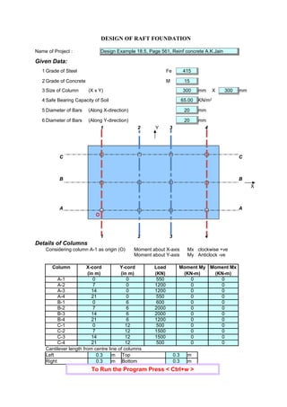
- 1. DESIGN OF RAFT FOUNDATION Name of Project : Design Example 18.5, Page 561, Reinf concrete A.K.Jain Given Data: 1 Grade of Steel Fe 415 2 Grade of Concrete M 15 3 Size of Column (X x Y) 300 mm X 300 mm 4 Safe Bearing Capacity of Soil 65.00 5 Diameter of Bars (Along X-direction) 20 mm 6 Diameter of Bars (Along Y-direction) 20 mm 1 2 Y 3 4 C C B B X A A O 1 2 3 4 Details of Columns Considering column A-1 as origin (O) Moment about X-axis Mx clockwise +ve Moment about Y-axis My Anticlock -ve Column X-cord Y-cord Load Moment My Moment Mx (in m) (in m) (KN) (KN-m) (KN-m) A-1 0 0 550 0 0 A-2 7 0 1200 0 0 A-3 14 0 1200 0 0 A-4 21 0 550 0 0 B-1 0 6 600 0 0 B-2 7 6 2000 0 0 B-3 14 6 2000 0 0 B-4 21 6 1200 0 0 C-1 0 12 500 0 0 C-2 7 12 1500 0 0 C-3 14 12 1500 0 0 C-4 21 12 500 0 0 Left 0.3 m Top 0.3 m Right 0.3 m Bottom 0.3 m KN/m2 Cantilever length from centre line of columns To Run the Program Press < Ctrl+w >
- 3. P = 13300 KN Eccentricity along x-direction Taking moment of column forces about the grid 1-1 x = 10.974 m = 10.974 - 10.5 = 0.474 m Eccentricity along y-direction Taking moment of column forces about the grid A-A y = 6.226 m = 6.226 - 6 = 0.226 m = 21.6 X 12.6 3 12 = 3600.68 = 12.6 X 21.6 3 12 = 10581.58 A = 12.6 X 21.6 = 272.16 = 3000.00 = 6300.00 P/A = 48.87 Soil pressure at different points is as follows s = P + .x + .y A Corner C-4 = 48.87 + 6300.00 10.8 + 3000.00 6.3 10581.58 3600.68 = 48.87 + 6.430 + 5.249 = 60.547 Corner A-4 = 48.87 + 6.430 - 5.249 = 50.049 Corner C-1 = 48.87 - 6.430 + 5.249 = 47.687 Total Vetical Column Load ex ey Ix m4 Iy m4 m2 Mxx = P.ey KNm Myy = P.ex KNm KN/m2 Myy Mxx Iy Ix sC-4 KN/m2 sA-4 KN/m2 sC-1 KN/m2
- 4. Corner A-1 = 48.87 - 6.430 - 5.249 = 37.189 Grid B-4 = 48.87 + 6.430 - 0.000 = 55.298 Grid B-1 = 48.87 - 6.430 - 0.000 = 42.438 Maximum Soil Pressure = 60.547 < 65.00 Hence OK In the X-direction, the raft is divided in three strips :- (i) Strip C-C Width = 3.3 m Soil Pressure = 60.547 Span = 7.00 m Maximum moment = 60.547 X 7 2 10 = 296.68 (ii) Strip B-B Width = 6 m Soil Pressure = 57.923 Span = 7.00 m Maximum moment = 57.923 X 7 2 10 = 283.82 (iii) Strip A-A Width = 3.3 m Soil Pressure = 52.674 Span = 7.00 m Maximum moment = 52.674 X 7 2 10 = 258.10 Cantilever Moment along X-direction Soil Pressure = 60.547 Span = 0.30 m Maximum moment = 60.547 X 0.3 2 2 = 2.72 (iii) Strip 4-4 Maximum Soil Pressure = 60.547 < 65.00 Span = 6 m Maximum moment = 60.547 X 6 2 8 = 272.46 sA-1 KN/m2 sB-4 KN/m2 sB-1 KN/m2 KN/m2 KN/m2 KN/m2 KNm/m KN/m2 KNm/m KN/m2 KNm/m KN/m2 KNm/m KN/m2 KN/m2 KNm/m
- 5. Cantilever Moment along X-direction Soil Pressure = 60.547 Span = 0.30 m Maximum moment = 60.547 X 0.3 2 2 = 2.72 Therefore, Maximum Factored Bending Moment = 445.02 Limiting Moment of Resistance = 0.138 Therefore depth required d = 470 mm Check for Punching Shear : Let depth required = 819 mm Shear Strength of Concrete = Where = 0.5 + = Short dimension of column = 1 Long dimension of column Therefore = 1 = 0.25 = 0.97 Hence, Shear Strength of Concrete = 0.97 For Corner Column Perimeter = 859 + 859 + 0 + 0 = 1719 mm Nominal Shear Stress = = 825000 1407109 = 0.59 For Side Column Perimeter = 1119 + 859 + 859 + 0 = 2837 mm Nominal Shear Stress = = 2250000 2322996 = 0.97 - = 0.00 Hence Effective depth is O.K. Therefore effective depth required = 819 mm Adopt effective depth = 820 mm Overall depth = 860 mm KN/m2 KNm/m KNm/m sck bd2 ks tc ks bc bc ks tc Ösck N/mm2 N/mm2 N/mm2 bo tv Vu bo d N/mm2 bo tv Vu bo d N/mm2 tv tc N/mm2
- 6. Development Length : = where, 1.6 x 1.0 = 1.6 Therefore, = 56 f For 20 mm bars (along X-direction) = 1120 mm For 20 mm bars (along Y-direction) = 1120 mm Reinforcement in long direction M = 4.45E+08 = 361.05 820 - 0.027667 9.98905 - 296061 + 4.45E+08 = 0 = 1588 Minimum reinforcement required = 0.12% = 1032 Therefore area of steel required = 1588 Provide 20 200 mm C/C in long direction (At top and bottom) Reinforcement in short direction M = 4.09E+08 = 361.05 820 - 0.027667 9.98905 - 296061 + 4.09E+08 = 0 = 1452 Minimum reinforcement required = 0.12% = 1032 Therefore area of steel required = 1452 Provide 20 220 mm C/C in short direction (At top and bottom) Development length Ld 0.87 sy f 4 tbd tbd = Ld Ld Ld 0.87 sy Ast (d - sy Ast /sck b) Ast ( Ast ) Ast 2 Ast Ast mm2 /m mm2 /m mm2 /m mm f bars @ 0.87 sy Ast (d - sy Ast /sck b) Ast ( Ast ) Ast 2 Ast Ast mm2 /m mm2 /m mm2 /m mm f bars @
- 7. DRAWING 21.60 12.60 20 200 mm c/c (top & bottom) 20 220 mm c/c (top & bottom) 20 200 mm c/c 0.860 20 220 mm c/c Note : (1) All dimension in m where not specified (2) Drawing not to scale (Reinforcement Details) mm f bars@ mm f bars @ mm f bars@ mm f bars@
- 8. DRAWING 21.60 12.60 20 200 mm c/c (top & bottom) 20 220 mm c/c (top & bottom) 20 200 mm c/c 0.860 20 220 mm c/c Note : (1) All dimension in m where not specified (2) Drawing not to scale (Reinforcement Details) mm f bars@ mm f bars @ mm f bars@ mm f bars@