2.instrumentation ii
•Download as PPTX, PDF•
2 likes•313 views

IOE TU microprocessor based instrumentation system instrumentation II

Recommended
More Related Content
What's hot
What's hot (20)
Similar to 2.instrumentation ii
Similar to 2.instrumentation ii (20)
Recently uploaded
Recently uploaded (20)
2.instrumentation ii
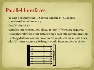
- 1. - ‘n’ data lines between I/O device and the MPU, all bits transferred simultaneously. - fast: ‘n’ bits/clock - complex implementation, since, at least ‘n’ wires are required. - Used preferably for short distance high data rate communication - For long distance communication, ‘n’ amplifiers on ‘n’ data lines, plus ‘n’ times excess cable length would increase cost ‘n’ times TRANSMITTER RECEIVER D0 D1 D2 D3 D4 D5 D6 D7
- 2. Simple I/O: No signalling is required, as the I/O device is always available to send/receive. Nature of data is continuos. e.g: LED connected to an o/p port; Display devices; Simple Strobed I/O: Valid data must be indicated with an accompanying strobe signal. Nature of data is intermittent. e.g: A keyboard; ADC
- 3. Single Handshaking: Receiver must confirm with a single acknowledgement [ACK], so that transmitter can proceed with the next data. Nature of data is essential which should not be lost or corrupted during transmission. Double Handshaking: Used when the receiver device is not always ready to receive. The sequence of events are - STB low: to query the receiver - ACK high: Receiver ready - Data transfer, STB high - ACK low: Read complete - Next cycle
- 4. 8255 is a low cost TTL compatible parallel interfacing device Few 82C55[CMOS version]/8255 specifications Sink Current: 2.5mA Max Current: 4.0mA Speed: 8MHz Three ports programmable in two groups: Group A: PA0-PA7; PC4-PC7 Group B: PB0-PB7; PC0-PC3 The 8255 is selected at four I/O addresses. In the PC, 8255 or its equivalent is selected at 60h-63h.
- 6. Mode 0 [Basic Input/ Output] “No handshaking” required Input port is simple buffered input and output port is simple latched output Two 8-bit ports: Port A, Port B Two 4-bit ports: PC0-PC3, PC4-PC7 Mode 2 [Strobed Bidirectional bus] Single handshaking or double handshaking can be implemented with software Bi-directional Data port: Port A 5-bit Data/Control port: Port C Mode 1 [Strobed Input/ Output] Latched input/ output Used at the input port with slower peripherals OR at the output port, when the CPU has to only occasionally send data Single handshaking or double handshaking can be implemented with software Data port: Port A Data/Control port: PC4-PC7 Data port: Port B Data/Control port: PC0-PC3
- 7. RESET resets all ports to simple input ports, mode 0 operation. To program the 8255, a command byte needs to be OUT to the port address corresponding to the command register MSB distinguishes between Command byte A and B Command byte B is used to set/reset port C bits individually (Bit Set Reset Mode)
- 8. Example 1: Q. Write a program to read DIP switches and display accordingly the LEDs. Soln: To read DIP switches, port A must be simple input port and to light the LEDs, port B must be simple output port. The necessary control word is 1 0 0 1 x 0 0 x 90h Let 8255 addresses be 60h-63h. The program is: ; program 8255 MVI A,90h ; control word OUT 63h ; OUT to control register ; begin I/O IN 60H ; read port A to accumulator OUT 61h ; OUT to port B from accumulator RET
- 9. Example: 2 Q. Write a program to set then reset PC7 till PC0 each after 1 second. Soln: The following will be the BSR control words to set/ reset each bit of port C
- 10. Port C will be independent input/output port in mode 0 only. Hence, the necessary control word to program the 8255 will be 1 0 0 0 0 0 0 0 80h The program segment is
- 12. New valid data is latched at input port from device. STB signal is lowered by the device, as an indicator to the 8255 of valid data. IBF is raised by the 8255 indicating that port contains data. INTR requested by 8255 to the microprocessor. Microprocessor issues an I/O RD, as per priority. 8255 acknowledges to microprocessor lowering INTR flag. 8255 lowers IBF indicating that port is empty
- 15. Example 3: Write a subroutine to read character from keyboard and print character. Soln: Port A is used in mode 1 strobed input to read character from keyboard. Port B is used in mode 1 strobed output to print character. The control word to program the 8255 is 1011x10x (B4h). PC4 must be read to check when a key is pressed (Polled I/O), or interrupt can be enabled (Interrupt-driven). To enable INTEA, set PC4. The BSR control word is 0xxx1001 (09h). To print a character, OBFB must be checked for not full (not zero), then the character can be sent. To read PC1, read port C, and AND with bit pattern 00000010 (02h) (mask all bits except PC1). Let the addresses be FCh-FFh. The program is