MODULE-II INFRASTRUCTURE ENGINEERING BTCVC702
•
1 like•686 views

This presentation helps you to understand all concepts as per DBATU, Lonere for Last Year BTech Civil Subject- Infrastructural Engg. Module-II Points and Crossings: Standard types, Design of simple turnout, various types of Junctions, Stations and Yards: Purpose, Location, Site selection, general layouts of Terminus and Junction, Signaling and Interlocking, Construction and Maintenance of Track, Modern trends in Railways etc.

Recommended
Recommended
More Related Content
What's hot
What's hot (20)
Similar to MODULE-II INFRASTRUCTURE ENGINEERING BTCVC702
Similar to MODULE-II INFRASTRUCTURE ENGINEERING BTCVC702 (20)
More from Dr. BASWESHWAR JIRWANKAR
More from Dr. BASWESHWAR JIRWANKAR (20)
Recently uploaded
Recently uploaded (20)
MODULE-II INFRASTRUCTURE ENGINEERING BTCVC702
- 1. Prepared by- Prof. Basweshwar S.J.
- 2. MODULE-2 Points and Crossings: Standard types, Design of simple turnout, various types of Junctions, Stations and Yards: Purpose, Location, Site selection, general layouts of Terminus and Junction, Signaling and Interlocking, Construction and Maintenance of Track, Modern trends in Railways Prepared by- Prof. Basweshwar S.J.
- 3. 2. Points and Crossings: • Points and crossings are provided to help transfer railway vehicles from one track to another. • The tracks may be parallel to, diverging from, or converging with each other. • Points and crossings are necessary because the wheels of railway vehicles are provided with inside flanges and, therefore, they require this special arrangement in order to navigate their way on the rails. • The points or switches aid in diverting the vehicles and the crossings provide gaps in the rails so as to help the flanged wheels to roll over them. • A complete set of points and crossings, along with lead rails, is called a turnout. Prepared by- Prof. Basweshwar S.J.
- 4. 2. Points and Crossings: Prepared by- Prof. Basweshwar S.J.
- 5. 2.1 Standard types • Turnouts and crossovers, including switches, frogs, guard rails, stock rails, and closure rails; rail fastening assemblies unique to turnouts; and miscellaneous components associated with turnouts, including switch rods and gauge plates. • Crossover tracks, double crossovers including the central crossing frogs or diamond area, and single and double slip switches are included in this category. • The cross ties to support turnouts and crossovers can also be considered part of special track work, especially concrete switch ties, which require far more design and fabrication effort than ordinary timber switch ties. Prepared by- Prof. Basweshwar S.J.
- 6. • Points (switch rails or point blades) are the movable rails which guide the wheels towards either the straight or the diverging track. • Stock rails are the running rails immediately alongside of the switch rails against which the switch rails lay when in the closed position. • Frog is a component placed where one rail crosses another, refers to the crossing point of two rails. • Closure rails are the straight or curved rails that are positioned in between the heel of switch and the toe of frog. • Guard rail (check rail) is a short piece of rail placed alongside the main (stock) rail opposite the frog. • Heel block assemblies are units placed at the heel of the switch that provide a splice with the contiguous closure rail and a location for the switch point rail to pivot at a fixed spread distance from the stock rail. • Switch point rail stops act as spacers between the switch point rail and the stock rail. • A switch operating device moves switch rails. Switch rails can be thrown (moved) from one orientation to another by either a hand- operated (manual) switch stand or a mechanically or electro-mechanically (power- operated) switch machine. Prepared by- Prof. Basweshwar S.J.
- 7. Turnout Types • A single crossover consists of two turnouts positioned in two tracks that allow the vehicle to go from one track to another. • The two tracks are usually, but not always, parallel, and the turnouts are usually identical. • A pair of single crossovers—one right hand and one left hand—that are arranged sequentially along the tracks is called a universal crossover. • A double crossover sometimes called a scissors crossover consists of two crossovers of opposite hand orientation superimposed upon each other. • In addition to the four turnouts involved, a track crossing diamond is needed between the two main tracks. Prepared by- Prof. Basweshwar S.J.
- 8. Turnout Types • Track crossings, as the name implies, permit two tracks to cross each other. • Track crossings are often called either crossing diamonds or simply diamonds, due to their plan view shape. • Lapped turnouts can be used to achieve a more compact track layout in constrained locations. Prepared by- Prof. Basweshwar S.J.
- 9. Prepared by- Prof. Basweshwar S.J.
- 10. 2.2 Design of simple turnout • The new track geometry of turnouts is usually set in the route plan in height and direction. • The marking out is done by the surveying department. • The marking out (to ensure the target geometry) by wooden poles is particularly important. • It is necessary to ensure that the piles are put in sufficiently deep that they do not get damaged or buried during the work. • A so-called turnout sketch is the basis for the procurement, construction and installation of turnouts and crossings. • The factory prepares a turnout laying plan on the basis of the turnout sketch for each turnout and crossing. • The sequence of the individual parts when building a simple turnout within the framework of the construction planning is set in relation to the selected turnout rework procedure, among other things, the space available for assembly and disassembly. Prepared by- Prof. Basweshwar S.J.
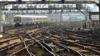
- 11. 2.3 Various types of Junctions • A junction, in the context of rail transport, is a place at which two or more rail routes converge or diverge. • This implies a physical connection between the tracks of the two routes (assuming they are of the same gauge), provided by points) and signaling. • Junctions are important for rail systems, their installation into a rail system can expand route capacity, and have a powerful impact upon on- time performance. Measures to improve junction capacity- • The capacity of the junctions limits the capacity of a railway network more than the capacity of individual railway lines. • The capacity of a railway junction can be increased with improved signaling measures, by building points suitable for higher speeds, or by turning level junctions into flying junctions. • With more complicated junctions such construction can rapidly become very expensive, especially if space is restricted by tunnels, bridges or inner-city tracks. Prepared by- Prof. Basweshwar S.J.
- 12. 2.3 Various types of Junctions Prepared by- Prof. Basweshwar S.J.
- 13. 2.4 Stations • A train station, railway station, railroad station or depot is a railway facility or area where trains regularly stop to load or unload passengers or freight or both. • It generally consists of at least one track-side platform and a station building (depot) providing such ancillary services as ticket sales, waiting rooms and baggage/freight service. • If a station is on a single-track line, it often has a passing loop to facilitate traffic movements. • The smallest stations are most often referred to as "stops" or, in some parts of the world, as "halts" (flag stops). • Stations may be at ground level, underground or elevated. • Connections may be available to intersecting rail lines or other transport modes such as buses, trams or other rapid transit systems. Prepared by- Prof. Basweshwar S.J.
- 14. 2.4 Stations Prepared by- Prof. Basweshwar S.J.
- 15. 2.4 Stations Purpose of a railway station: • For exchange of passengers • For exchange of goods. • For control of train movements • To enable the trains on a single line track to cross from opposite directions. • To enable the following express trains to overtake • For taking diesel or coal and water for locomotives • For detaching engines and running staff • For detaching or attaching of compartments and wagons. • For sorting of bogies to form new trains, housing of locomotive in loco sheds. • In emergencies in ease of dislocation of track due to rains, accidents etc... Prepared by- Prof. Basweshwar S.J.
- 16. 2.4 Stations Station : Means any place on a line of railway at which traffic is dealt with, or at which an authority to proceed is given to the driver of the train under the system of working. Block stations : Block stations are those at which driver must obtain an authority to proceed under the system of working to enter the block section with his train. Non-Block station : These are outlets opened for commercial purpose and no block working is carried here. To cope up with different working conditions stations are categorized into various classes. Prepared by- Prof. Basweshwar S.J.
- 17. 2.4 Stations Class A Station : Where line clear may not be given for a train unless the line on which it is intended to receive the train is clear for at least 400 Mts., beyond the Home signal or up to the starter. Class B Station : Where line clear may be given for a train before the line has been cleared for the reception of the train within the station section. Prepared by- Prof. Basweshwar S.J.
- 18. 2.4 Stations Class C Station : At which no train is booked to stop. This includes IBS, line clear may not be given for a train, unless the whole of the last proceeding train has passed completely at least 400 Mts. beyond the Home signal and is continuing its journey. Class D Station : Situated between two consecutive block stations and do not form the boundary of any block section. Minimum signaling equipment required for each class of station Prepared by- Prof. Basweshwar S.J.
- 19. 2.4 Stations Prepared by- Prof. Basweshwar S.J.
- 20. 2.5 Yards • An area consisting of a network of railway tracks, sidings, and sheds for storing, maintaining, and joining engines and carriages. • A yard is defined as a system of tracks laid within definite limits for various purposes such as receiving sorting and dispatch of vehicles. Prepared by- Prof. Basweshwar S.J.
- 21. Passenger yards Goods yards Function of passenger yard is to provide all the facilities for the safe movement of passengers. Facilities in passenger yards • Booking office, enquiry office, luggage booking room, cloak room and waiting room for passengers • Parking space for vehicles • Signals for reception and dispatch of trains • Platforms and sidings for shunting facilities • Facilities for changing batteries • Facilities for passing a through train • Washing lines, sick lines facilities A goods station (also known as a goods yard, goods depot or freight station) is, in the widest sense, a railway station which is exclusively or predominantly where goods (or freight) of any description are loaded or unloaded. Facilities at Goods Yards • These are provided for receiving, loading and unloading of goods. • Approach road for movement of goods • Sufficient number of platforms for loading and unloading • Sufficient number of godowns • Booking office • Cart weighing machine • Cranes for loading and unloading • Vacuum testing machine Prepared by- Prof. Basweshwar S.J.
- 22. Marshalling yards A yard is a classifying and distributing machine with facilities for receiving, sorting and dispatching wagons to their various destinations after the prescribed attention. Factors for the efficient functioning of marshalling yards- • Shunting operations should not disturb the regular trains • Should be kept parallel to the running trains • Movement of wagons in one direction only • Repair facilities should be provided on one or more sidings • Connected to all important railway stations • Goods yard should be nearer to the marshalling yard. (i) Flat yard • Flat yards are constructed on flat ground, or on a gentle slope. • Freight vehicles are pushed by a locomotive and coast to their required location. (ii) Gravity yard • The whole yard is set up on a continuous falling gradient and there is less use of shunting engines. (iii) Hump yard • A hump yard has a constructed hill, over which freight cars are shoved by yard locomotives, and then gravity is used to propel the cars to various sorting tracks. Prepared by- Prof. Basweshwar S.J.
- 23. Locomotive yards This is the yard which houses the locomotives for various facilities such as watering, fueling, cleaning, repairing, servicing etc. Requirements- • Should be located near the passenger and goods yards • Water column • Engine shed, Ash pit, inspection pit, repair shed, turn table • Hydraulic jack for lifting operations • Over head tank and loco well • Sick siding • Place for future expansion Prepared by- Prof. Basweshwar S.J.
- 24. Locomotive yards Requirements- • Should be located near the passenger and goods yards • Water column • Engine shed, Ash pit, inspection pit, repair shed, turn table • Hydraulic jack for lifting operations • Over head tank and loco well • Sick siding • Place for future expansion Prepared by- Prof. Basweshwar S.J.
- 25. 2.5 Signaling and Interlocking Railway signalling is a system used to control railway traffic safely, essentially to prevent trains from colliding. Signaling consists of the systems, device and means by which trains are operated efficiently and tracks are used to maximum extent, maintaining the safety of the passengers, the staff and the rolling stock. It includes the use and working of signals, points, block instruments and other equipments. Prepared by- Prof. Basweshwar S.J.
- 26. 2.5 Signaling and Interlocking OBJECTIVES- • To provide facilities for the efficient moving of trains. • To ensure safety between two or more trains which cross or approach each other's path. • To provide facilities for the maximum utility of the track. • To provide facilities for safe and efficient shunting operations. • To guide the trains movement during maintenance and the repairs of the track. • To safeguard the trains at converging junctions and give directional indications of diverging junctions. Prepared by- Prof. Basweshwar S.J.
- 27. Classification of Signaling (a) Stop signals or semaphore type signals (b) Warner signals • One of the earliest forms of fixed railway signal is the semaphore. • These signals display their different indications to train drivers by changing the angle of inclination of a pivoted 'arm‘. • The stop position is the normal position and it is said to be ON position. • The arm can be lowered at an angle of 400 to 600 with horizontal and is said to be OFF position. • The warner signal is similar to semaphore signal in shape except a v-notch at free end, i.e. The movable arm is fish tailed as shown. • The white band is also of v- shape. • The warner signal is placed on the same post of the semaphore signal 1.8 to 2.1m below the semaphore signal. • The warner signal is painted yellow and exhibits yellow or amber colour at night instead of red colour. Prepared by- Prof. Basweshwar S.J.
- 28. Classification of Signaling (c) Disc or ground signals (d) Colored light signals • These signals are used for shunting operations in station yards. • They are of the shape of a circular disc with a red band on a white back ground. • The disc can revolve in a vertical plane by pulling the lever by hand. • Two holes are provided, one for red lamp and the other for the green lamp. • When the red band is horizontal or shows red light at night it indicates ―STOP • When the red band is inclined at 45 degree or shown green light at night indicates ―PROCEED. • Semaphore signals are being replaced by high intensity beam colour light signals both during day and night. • In case of colour light signals, the normal position is to indicate ―PROCEED (i.e., shows green light) • When the section is blocked, it automatically indicates ―STOP or ―DANGER (i.e., shows red light) • In India these signals are used on urban and sub- urban sections with heavy traffic. Prepared by- Prof. Basweshwar S.J.
- 29. Locational Characteristics of Signals (i)Reception signals (a) Outer signal (b) Home signal • This is the first stop signal which indicates the entry of the train from block to the station yard. • It should be placed at an adequate distance (0.54km for BG and 0.4 km for MG). • It has one arm but may have a warner signal on the same post nearly 2m below it. • In the Stop position the driver must bring his train to a stop at a distance of about 90m before the outer signal and then proceed to the home signal with caution. • If it is in the Proceed position then the driver can take the train at speed, assuming that home signal is also in the proceed position. • Due to its location at the door of station, it is termed as Home signal. • The home signal has bracketed arms to indicate which line is to be used. • The function of home signal is to protect the sidings already occupied. • It is located at not more than 180m from the start of points of switches. • Home signals carry as many arms as the number of diverging lines. Prepared by- Prof. Basweshwar S.J.
- 30. Locational Characteristics of Signals (ii) Departure signals (a) Starter • It marks the limit up to which trains stopping at a station should come to a stand. • The starter is the last stop signal at a station. • It controls the movements of the trains when they depart from the stations. • No train can leave the station unless the starter signal shows the ―PROCEED position. • Besides the starter signal for each of the station lines from which trains starts, an advance starter may also be provided. • The advance starter becomes the last stop signal at the stations where is provided. • It is an indication for the train having left the station. (b) Advance Starter Prepared by- Prof. Basweshwar S.J.
- 31. Prepared by- Prof. Basweshwar S.J.
- 32. Interlocking • In railway signaling, an interlocking is an arrangement of signal apparatus that prevents conflicting movements through an arrangement of tracks such as junctions or crossings. • An arrangement of signals and signal appliances so interconnected that their movements must succeed each other in proper sequence". • In general terms an interlocking is a location where plain track ends and track work with points and crossings complicate train movements. These areas are likely to be:- • Junctions where two or more main lines meet. • Complex yards or sidings are encountered. These may be at larger towns or depot facilities. • An interlocking provides for complex train movements and shunting of trains. • It provides for the protection of multiple train movements within a localized area. Prepared by- Prof. Basweshwar S.J.
- 34. Interlocking • The signals and points are operated by means of levers. • Levers are located at ground level or platform level or in an elevated structure called signal box or signal cabin. • Interlocking is done by grouping levers at one point. • The levers are painted for easy identification. • There are three methods of interlocking • Tappets and lock system • Key system • Route relay system. Prepared by- Prof. Basweshwar S.J.
- 35. Interlocking There are three methods of interlocking Tappets and lock system Key system Route relay system • This method is useful when levers are to be interlocked so as to prevent conflicting movement. • The tappers are of steel sections. 38mm X 16mm with suitable recesses and notches. They are attached to the levers. • The locks are also of steel with shapes to suit the recesses in the tappers. • The lock move at right angle to the tappers. • In this system, the points and signals for movements of trains are electrically operated. • This is the mode and sophisticated system of interlocking. • Due to this system there is a considerable saving of man power and maintenance expenditure of cabins. • This is the simplest method of interlocking. The key locks are manipulated in this system • The principle of this system is to provide two locks which are worked by a single key. • With drawl of the key locks the signal in the horizontal position and the points in the normal setting for the main line. Prepared by- Prof. Basweshwar S.J.
- 36. CONTROL OF TRAIN MOVEMENTS- It is quite essential that movements of trains on particular tracks should be safe and for this purpose various methods are found out. (i)Following trains system (ii)Absolute block system (iii)Automatic signaling (iv)Pilot guard system Prepared by- Prof. Basweshwar S.J.
- 37. CONTROL OF TRAIN MOVEMENTS- (i)Following trains system (ii)Absolute block system • Used in case of emergencies such as failure of telegraph and telephone systems. • In this method, a fixed interval of time is maintained between the departure of one train and the departure of the next train along the same time. • This fixed interval is worked out in such a way that sufficient distance or headway in maintained between the tail of the first train and the head of the next following train. • The principle of the absolute block system of railway signaling is to ensure the safe operation of a railway by allowing only one train to occupy a defined section of track at a time. • Instead of a fixed interval of time between successive trains, a varying interval may be kept depending on the time, actually taken by particular trains. • It is a space interval system rather than a fixed interval system. • The electric telegraph provided the ability for signalmen to communicate with each other and provided the basis for the absolute block system Prepared by- Prof. Basweshwar S.J.
- 38. CONTROL OF TRAIN MOVEMENTS- (iii)Automatic signaling (iv)Pilot guard system • In order to avoid accidents, automatic signaling has been found out. • In this signals are operated by trains themselves. • An electric current is conveyed through the track when a train occupies that particular track and this current puts the signal at danger position until the train has gone far ahead so as to require no further protection. • Used on certain occasions such as breakdown of telephone and telegraph system on a single line and one track of a double line being out of order. • In this system, a pilot proceeds by one train to the station ahead and then he returns by a train running in the opposite direction. Prepared by- Prof. Basweshwar S.J.
- 39. Automatic Block System- Prepared by- Prof. Basweshwar S.J.
- 40. 2.6 Construction of Track 1. Telescopic Method of Construction 2. Tram line Method of Construction 3. Mechanical Methods • In this method of construction rails, sleepers, fastenings are unloaded from the material train as closer to rail head as possible. • The sleepers are carried by cart or by men along the adjoining service road and spread on the ballast. • The rails are then carried on pairs to the end of last pair of connected rails and linked. • This method is used where tram carrier are installed for carrying earthwork or in rainy season due to difficulty in movement of cart. • The basic difference between Telescopic and Trame line lies in the conveyance and spreading of sleepers. • This method is extensively used by special machines. • There are two types of machines available- • In the first type track material carried by the material train and delivered at rail head and laid in the required position by means of projecting arm mounted on the truck nearest to the rail head. The material train moves forward on the assembled track and operation repeated. • In the second method a long cantilevered arm projecting beyond fitted on the wagon. A panel of assembled track consisting pair of rails with number of sleepers on the ballast layer. It is lowered by the jib at the required position and connected to the previous panel. The train moves on and operation repeated. Prepared by- Prof. Basweshwar S.J.
- 41. 2.7 Maintenance of Track • Track geometry is three- dimensional geometry of track layouts and associated measurements used in design, construction and maintenance of railroad tracks. • The subject is used in the context of standards, speed limits and other regulations in the areas of track gauge, alignment, elevation curvature and track surface. • Although, the geometry of the tracks is three-dimensional by nature, the standards are usually expressed in two separate layouts for horizontal and vertical. Existing System of track Maintenance 1. Manually 2. Three tier system of maintenance • The track should be maintained either by conventional system of track maintenance or by three – tier system of track maintenance. • In both the systems, track requires to be overhauled periodically with the object of restoring it to best possible condition, consistent with its maintainability. • Periodicity of overhauling depends on several factors, such as type of track structure, its age, volume of traffic, rate of track deterioration, maximum permissible speed, system of traction, condition. Prepared by- Prof. Basweshwar S.J.
- 42. (1) 3- tier system of track maintenance shall be adopted on sections nominated for mechanized maintenance. This shall consist of the following 3 tiers of maintenance- (i) On track machines (ii) Mobile maintenance units (iii) Sectional gangs (B) Three tier system of track maintenance: - (2) Large track machines for track maintenance include tie- tamping machines for plain track and points and crossings, shoulder ballast cleaning machines, ballast-cleaning machines, ballast regulating machines and dynamic track stabilizers. These machines shall be used as per the various instructions issued in Indian Railways Track Machines Manual. These machines shall be deployed to carry out the following jobs. (a) Systematic tamping of plain track as well as points and crossings. (b) Intermediate tamping of plain track as well as points and crossings. (c) Shoulder ballast cleaning. (d) Ballast profiling / redistribution. (e) Track stabilization. (f) Periodical deep screening. (3) Mobile Maintenance Units- (a) The mobile maintenance units (MMU) shall consist of two groups- (i) MMU-I one for each PWI’s section (ii) MMU-II one for each sub division. (b) The functions of MMU shall be as below: 1.Track Relaying Activities and Existing system of Relaying. 2. Turnout relaying At present both these activities are performed both manually and by machines. Prepared by- Prof. Basweshwar S.J.
- 43. 2.8 Modern trends in Railways • Rapid transport is a type of high-capacity public transport generally found in urban areas. • Unlike buses and trains, rapid transport systems operate on an exclusive right-of-way which is usually grade separated in tunnels or elevated railways. • Metro is the most common term for underground rapid transport systems. • Rapid transport is used in cities and metropolitan areas to transport large numbers of people often short distances at high frequency. • The extent of the rapid transport system varies greatly between cities, with several transport strategies. Prepared by- Prof. Basweshwar S.J.
- 44. 2.8 Modern trends in Railways Prepared by- Prof. Basweshwar S.J.
- 45. 2.8 Modern trends in Railways Prepared by- Prof. Basweshwar S.J.