SlideShare a Scribd company logo
1 of 36
Download to read offline
4.1 Bridge Engineering: Super-structures
4.2 Simple bridges or beam bridges: Deck bridges, Through bridges,
Semi-through bridges
4.3 Introduction, advantages and disadvantages: Continuous bridges,
Cantilever bridges, Arch bridges, Bow-string girder type bridges, Rigid
frame bridges, Portal frame bridges, Suspension bridges, Cable-stayed
bridges, Composite bridges
4.4 Materials for super-structures: Cement concrete, Masonry, Steel,
Timber
Prepared by-
Prof. Basweshwar S. J.
Prepared by-
Prof. Basweshwar S. J.
• A bridge is a structure built to span a physical obstacle,
such as a body of water, valley, or road, without
closing the way underneath.
• It is constructed for the purpose of providing passage
over the obstacle, usually something that is otherwise
difficult or impossible to cross.
• There are many different designs that each serve a
particular purpose and apply to different situations.
• Designs of bridges vary depending on the function of
the bridge, the nature of the terrain where the bridge is
constructed and anchored, the material used to make
it, and the funds available to build it.
Prepared by-
Prof. Basweshwar S. J.
• Cantilever- For small footbridges, the cantilevers may be simple beams; however, large cantilever
bridges designed to handle road or rail traffic use trusses built from structural steel, or box girders
built from Prestressed concrete.
• Suspension- The cables are usually made of steel cables galvanized with zinc, along with most of
the bridge, but some bridges are still made with steel-reinforced concrete.
• Arch- Stone, brick and other such materials that are strong in compression and somewhat so in
shear.
• Beam- Beam bridges can use pre-stressed concrete, an inexpensive building material, which is then
embedded with rebar. The resulting bridge can resist both compression and tension forces.
• Truss- The triangular pieces of truss bridges are manufactured from straight and steel bars,
according to the truss bridge designs.
Prepared by-
Prof. Basweshwar S. J.
4.1 Bridge Engineering: Super-structures
• The definition of superstructure covers the structure of the bridge which directly takes the load
and transmits to the supports on either side.
• This is the portion spanning across the gap.
• In the earliest days of development of bridges, one or more timber logs were laid across the gap
and some flooring arrangement.
Prepared by-
Prof. Basweshwar S. J.
Prepared by-
Prof. Basweshwar S. J.
4.2 Simple bridges or beam bridges:
• Beam bridges, also known as stringer bridges, are the simplest structural forms for bridge spans
supported by an abutment or pier at each end.
• No moments are transferred throughout the support, hence their structural type is known as
simply supported.
• Material: Timber, iron, steel, reinforced concrete
Prepared by-
Prof. Basweshwar S. J.
4.2.1 Deck bridges
• A deck is the surface of a bridge.
• A structural element of its superstructure, it
may be constructed of concrete, steel, open
grating, or wood.
• Sometimes the deck is covered a railroad bed
and track, asphalt concrete, or other form of
pavement for ease of vehicle crossing.
• A concrete deck may be an integral part of the
bridge structure (T-beam or double tee
structure) or it may be supported with I-beams
or steel girders.
Prepared by-
Prof. Basweshwar S. J.
4.2.2 Through bridges
A through arch bridge, also known as a half-through arch bridge or a through-type arch bridge, is a
bridge that is made from materials such as steel or reinforced concrete, in which the base of an arch
structure is below the deck but the top rises above it.
Material: Steel
Prepared by-
Prof. Basweshwar S. J.
4.2.3 Semi-through bridges
• A deck type bridge is the one in which the roadway/railway floor rests on the top of the
supporting structures, while a through bridge is the one where the roadway/railway floor rests on
the bottom of the main load supporting structure.
• However, when the floor lies between the top and bottom of the main supporting structure, it is
known as half through type bridge, semi-through bridge or pony bridge.
Prepared by-
Prof. Basweshwar S. J.
4.3.1 Introduction of
Continuous bridges-
• Continuous bridges are more
economical but lack simplicity in the
design procedure.
• These structures have the relative
advantage that their designs are simple
and do not involve any complicated
analysis but the main drawback is that
such structures are generally
comparatively costly.
Continued…
Prepared by-
Prof. Basweshwar S. J.
4.3.1 Advantages and disadvantages of Continuous bridges-
Advantages-
(i) Unlike simply supported bridges, these structures require
only one line of bearings over piers thus reducing the
number of bearings in the superstructure as well as the
width of the piers.
(ii) Due to reduction in the width of pier, less obstruction to
flow and as such possibility of less scour.
(iii) Require less number of expansion joints due to which
both the initial cost and the maintenance cost become less.
The riding quality over the bridge is thus improved.
(iv) Reduces depth at mid-span due to which vertical
clearance or headroom is increased. This may bring down the
bridge deck level reducing thereby not only the cost of the
approaches but also the cost of substructure due to lesser
height of piers and abutments which again reduces the cost
of the foundation.
(v) Better architectural appearance.
Disadvantages-
(i) Analysis is laborious and time consuming.
(ii) Not suitable on yielding foundations. Differential
settlement may cause undesirable stresses.
Design Procedure of Continuous Bridges:
1. Fix up span lengths in the unit and select rough sections at
mid-spans and at supports.
2. Select appropriate soffit curve.
3. Work out dead load moments at different sections etc.
Prepared by-
Prof. Basweshwar S. J.
4.3.2 Introduction of Cantilever bridges-
• A cantilever bridge has the same function of any other bridge; to span obstacles to provide passage over it
for pedestrians, vehicles or railways.
• This type of bridge is selected when necessity supports cannot be provided at specific positions, due to
the great straining actions.
Continued…
Prepared by-
Prof. Basweshwar S. J.
4.3.2 Advantages and disadvantages of Cantilever bridges-
Advantages-
• Assembled sections of suspended bridges can only be
elevated and attached between two cantilever spans.
• Support are required on only one side of each cantilever.
• The bridge floor might be simply formed into sections,
which preserve uniformity and ensure high quality.
• These bridges have multiple cantilever spans,
construction can be started immediately from all its
columns reducing the time required.
• Navigation under the bridge is not interrupted during its
construction.
• In areas with a strong rock structure, anchor arms might
be connected to the surrounding rock, without the
necessity for synthetic support.
• The span of those bridges is longer than conventional
beams since the cantilever are attached at the ends of the
bridge.
Disadvantages-
• Extensive analysis to prevent fatigue failure of elements
and welds.
• These are large-scale structures, which are complex to
construct and maintain.
• These bridges are heavy, cantilevers require must be
bigger and stronger support columns.
• They will not be suited for earthquake-prone areas or
areas with low-rock stability.
Design Procedure of Cantilever Bridges:
1. The cantilever bridge is different from simply supported
structures.
2. Simply supported structures are directly supported at
each end, whereas cantilevered structures are directly
supported at one end and free at the other end etc.
Prepared by-
Prof. Basweshwar S. J.
4.3.3 Introduction of Arch bridges-
• An arch bridge is a bridge with abutments at each
end shaped as a curved arch.
• Arch bridges work by transferring the weight of the
bridge and its loads partially into a horizontal
thrust restrained by the abutments at either side.
• A viaduct (a long bridge) may be made from a series
of arches, although other more economical
structures are typically used today.
Continued… Prepared by-
Prof. Basweshwar S. J.
4.3.3 Advantages and disadvantages of Arch bridges-
Advantages-
• Provides a better level of resistance.
• Design is good in terms of pressure.
• An arch bridge is often made from stone, bricks or nearly
the other natural material that has the standard of
withstanding forces of compression.
• Structurally sound.
• The half-circle form of an arch bridge is by design
designed to create certain that no distortion or injury
would occur to the structure because of extreme pressure
or weight.
• Becomes stronger because it works.
• Offers economic advantages.
Disadvantages-
• Restricted span:.
• Constraints on the location.
• Needs additional maintenance.
• Needs additional support.
• Will take long to build.
• Pricey to build.
Design Procedure of Arch Bridges:
1. Arch Analysis.
2. False work centering.
3. Deck raising.
4. Road development etc.
Prepared by-
Prof. Basweshwar S. J.
4.3.4 Introduction of Bow-string girder type
bridges-
• A tied-arch bridge is an arch bridge in which the
outward-directed horizontal forces of the arch(es) are
borne as tension by a chord tying the arch ends, rather
than by the ground or the bridge foundations.
• This strengthened chord may be the deck structure
itself or consist of separate, deck-independent tie-rods.
• Thrusts downwards on a tied-arch bridge deck are
translated, as tension, by vertical ties between the deck
and the arch, tending to flatten it and thereby to push its
tips outward into the abutments, like for other arch
bridges.
Continued…
Prepared by-
Prof. Basweshwar S. J.
4.3.4 Advantages and disadvantages of Bow-string girder type bridges-
Advantages-
• It offers higher levels of resistance compared to other
designs.
• It offers the option to span a greater distance.
• It can be construction from almost any material.
• It provides an advantage when carrying loads.
• It continues to provide support without distortion over
time.
• It can become stronger over time.
• It adapts to local environmental conditions better.
Disadvantages-
• It offers a finite span length to use.
• It is a time-consuming project to complete.
• It is a structure which requires careful maintenance.
• It is a bridge option that cannot be built in some
locations.
• It requires more side support to complete a successful
span.
• It requires expertise to build.
Design Procedure of Bow-String girder Bridges:
1. Arch Analysis with end support loadings
2. False work centering.
3. Deck lifting
4. Road development etc.
Prepared by-
Prof. Basweshwar S. J.
4.3.5 Introduction of Rigid frame bridges-
• A Rigid-frame bridge is a bridge in which the superstructure and substructure are rigidly connected to act
as a continuous unit.
• Typically, the structure is cast monolithically, making the structure continuous from deck to foundation.
• The connections between members are rigid connections which transfer bending moment, axial forces,
and shear forces.
• A bridge design consisting of a rigid frame can provide significant structural benefits, but can also be
difficult to design and/or construct.
Continued…
Prepared by-
Prof. Basweshwar S. J.
4.3.5 Advantages and disadvantages of Rigid frame bridges-
Advantages-
• More rigidity of the structure.
• Less moments in deck being partly transferred to the
supporting members.
• No bearings are required.
Design Procedure of Rigid Frame Bridges:
1. Arch Analysis with end support loadings
2. False work centering.
3. Deck lifting
4. Road development etc.
Disadvantages-
• There are no built-in supports for beam bridges.
• Span limitations exist for beam bridges.
• Beam bridges can sometimes start to sag as they age.
• There is little aesthetic value to consider with a beam
bridge.
• The cost of steel often dictates any price advantages
which may be present.
• Beam bridges can go through a significant amount of
wear-and-tear in their lifetime.
• Beam bridges do not offer a lot of flexibility.
• Requires more on maintenance costs with beam bridges
when compared to other designs.
• The width of the deck span is limited with a beam
bridge.
Prepared by-
Prof. Basweshwar S. J.
4.3.6 Introduction of Portal frame bridges-
• Portal frames are generally designed for use below ground to provide waterways or pedestrian subways.
• The units are supported on in situ concrete foundations.
• Seals are provided between successive units to ensure a water-tight structure.
• The dimensions of the units and their weights will be limited by the requirements for transportation and
installation.
• Similar units may be designed for use above ground to form integral bridge type structures or frames for
building structures.
Continued…
Prepared by-
Prof. Basweshwar S. J.
4.3.6 Advantages and disadvantages of Portal frame bridges-
Advantages-
• When compared to conventional bridges, construction
costs and maintenance costs are much lower.
• Construction of integral bridges is simple and rapid.
• If new bridge is constructing in place of existing old
bridge, the foundation of old bridge can be used as
foundation for new bridge. Hence cost of project reduces.
• Elimination of water leakage on critical structural
elements can be done using drainage layer provided
behind the integral abutments.
• The vehicle riding quality on integral bridge is more
comfortable and smooth since there are no expansion
joints.
Disadvantages-
• These bridges are not suitable in zones where there is
chance of expansion/contraction of more than 51mm
during temperature variations.
• They are not preferred when subsoil or embankments
are of poor strength.
• Geometry of the bridge and material used for the
construction play key role in case of these bridges.
• They are responsible for the displacement affects in the
bridge.
Design Procedure of Portal Frame Bridges:
• Portal Frame Analysis with end moments
• Casting.
• Deck construction.
• Road development etc.Prepared by-
Prof. Basweshwar S. J.
4.3.7 Introduction of Suspension bridges-
• A suspension bridge is a type of bridge in which the deck is hung below suspension cables on vertical
suspenders.
• The basic structural components of a suspension bridge system include stiffening girders/trusses, the
main suspension cables, main towers, and the anchorages for the cables at each end of the bridge.
• The main cables are suspended between towers and are finally connected to the anchorage or the bridge
itself, and vertical suspenders carry the weight of the deck and the traffic load on it. Continued…
Prepared by-
Prof. Basweshwar S. J.
4.3.7 Advantages and disadvantages of Suspension bridges-
Advantages-
• Cost Effective.
• Can Be Built High Up.
• Span Great Lengths.
• Simple Construction
Disadvantages-
• Soft Ground Issues
• Too Flexible
• Cannot Support High Traffic
Design Procedure of Suspension
Bridges:
1. Loading identification
2. Suspenders and span criteria
3. Suspender launching
4. Girder launching etc.
Prepared by-
Prof. Basweshwar S. J.
• A cable-stayed bridge offers a design that is similar to a
suspended bridge.
• It will have towers that help to support the structure, while
the deck is held in place by cables.
• The difference in the design is that the cables hold the deck by
connecting it directly to the support pillars instead of using
suspending wires or cables to stabilize the span.
• This bridge type is useful for numerous traffic options,
including automobiles, trucks, bicycles, and pedestrians.
• In some situations, a cable-stayed bridge is suitable for light
rail as well.
• Engineers use this option when a span must be longer than
what a cantilever bridge can support because of its weight,
yet it is also short enough so that a suspension bridge is not
the most practical option.
Continued…
4.3.8 Introduction of Cable-stayed bridges-
Prepared by-
Prof. Basweshwar S. J.
4.3.8 Advantages and disadvantages of Cable-stayed bridges-
Advantages-
• Cable-stayed bridges take less time to complete than
other options.
• The strength of a cable-stayed bridge is unquestionable.
• It can be significantly cheaper to build a cable-stayed
bridge.
• Cable-stayed bridges can be constructed to almost any
length.
• There are multiple design options from which to choose
with a cable-stayed bridge.
• The design of the cable-stayed bridge supports itself.
• Cable-stayed bridges offer the possibility of a
symmetrical design.
Disadvantages-
• Cable-stayed bridges do have a maximum length to
consider.
• This design option can become unstable in specific
environments.
• Cable-stayed bridges can be challenging to inspect and
repair.
• It is a design that can sometimes be susceptible to rust or
corrosion.
• The strength advantages typically apply to short spans.
Design Procedure of Cable- Stayed Bridges:
• Loading Analysis
• Aided software
• Launch of Elements
• Suspender checks etc.Prepared by-
Prof. Basweshwar S. J.
4.3.8 Introduction of Composite bridges-
• 'Composite' means that the steel structure of a bridge is fixed to
the concrete structure of the deck so that the steel and concrete
act together, so reducing deflections and increasing strength.
• This is done using 'shear connectors' fixed to the steel beams
and then embedded in the concrete.
• Shear connectors can be welded on, perhaps using a 'stud
welder', or better still on export work, by fixing nuts and bolts.
• Usually the steel carries its own weight and that of the wet
concrete. But when the concrete is 'cured' and has acquired its
full strength, then all future loads (traffic, surfacing, wind,
water, pressure, seismic loads) are shared by the steel/concrete
composite.
• The concrete is good in compression, while the steel is good in
tension and compression.
Continued…
Prepared by-
Prof. Basweshwar S. J.
4.3.8 Advantages and disadvantages of Composite bridges-
Advantages-
• High torsional stiffness and strength this enables the use
of box girders in horizontally curved bridges and
interchanges.
• Greater aerodynamic stability;
• Reduced susceptibility to lateral buckling of flanges in
lateral-torsional and distortional buckling modes;
• Support point required are less compared to
conventional systems.
• Improved durability.
• Reduced maintenance of protective coatings since the
exposed surface is less and fewer edges are there and
avoidance of exposed horizontal surfaces, no exposed
bracing and stiffeners;
• Clean lines of a closed box girder provide better
appearance for footbridges where the visual impact
counts.
Disadvantages-
• Greater fabrication cost due to reduced scope for
automated fabrication;
• Handling during fabrication and coating is very difficult;
• Greater design input;
• Risks associated with working in enclosed spaces.
Design Procedure of Composite Bridges:
• Loading Analysis
• Aided software
• Launch of Elements
• Combination checks in steel and concrete etc.
Prepared by-
Prof. Basweshwar S. J.
Prepared by-
Prof. Basweshwar S. J.
4.4 Materials for super-structures-
• Some of the main typical materials that are found on a bridge are steel, concrete, stone and asphalt.
• Other materials include iron, timber, aluminum, rubber and other joint materials.
• Concrete is commonly used for many bridge superstructure members such as decks, pre-stressed concrete
beams, curbs, sidewalks and parapets (side traffic barrier walls).
• Steel is commonly used in the bridge superstructure for armoring expansion joints, beams, bearings, floor
beams, girders, reinforcing bars in concrete, traffic barriers and trusses.
• Stone was commonly used for building the abutments and piers in the 1940’s and earlier.
• Asphalt is the material that has been used extensively for the wearing surfaces on corrugated metal decks,
timber decks and concrete decks.
• Iron was used typically in beams and trusses that were built before 1900.
• Timber is used for several decks and traffic barriers. It is also used for the beams on one bridge and the
abutments and piles on another bridge.
• Aluminum is sometimes used in fabricating bridge railings.
• Rubber and synthetic rubber products are used for bearings and for expansion joint material.
Prepared by-
Prof. Basweshwar S. J.
4.4.1 Cement concrete-
• Concrete is a composite material composed of fine and
coarse aggregate bonded together with a fluid cement
(cement paste) that hardens (cures) over time.
• In the past lime based cement binders were often used,
such as lime putty, but sometimes with other
hydraulic cements, such as a calcium aluminate
cement or with Portland cement to form Portland
cement concrete (named for its visual resemblance to
Portland stone).
• Many other non-cementitious types of concrete exist
with other methods of binding aggregate together,
including asphalt concrete with a bitumen binder,
which is frequently used for road surfaces, and polymer
concretes that use polymers as a binder.
Prepared by-
Prof. Basweshwar S. J.
4.4.2 Masonry-
• A bridge whose main load-bearing structures are made of natural
stone, brick, or concrete blocks.
• Such a bridge is always arched, with massive supports.
• The spandrel is made from a gravel or crushed stone backing held in
by lateral (side) walls made of concrete masonry or stonework or in
the form of an open structure of small arches resting on crosswalk.
• The advantages of a masonry bridge are its architectural at-tractive
ness and its durability.
• Masonry bridges are known that have been in use for more than 1,000
years.
• The basic shortcomings that limit the use of masonry bridges are
their complexity and labor-intensiveness of construction.
• A variation of a masonry bridge is the concrete bridge, which has an
arch made of cast concrete. Prepared by-
Prof. Basweshwar S. J.
4.4.3 Steel-
• Steel is widely used around the world for the construction of
bridges from the very large to the very small.
• It is a versatile and effective material that provides efficient and
sustainable solutions.
• Steel has long been recognized as the economic option for a
range of bridges.
• It dominates the markets for long span bridges, railway
bridges, footbridges, and medium span highway bridges.
• It is now increasingly the choice for shorter span highway
structures as well.
• Steel bridges are an essential feature of a country’s
infrastructure and landscape.
• Few man-made structures combine the technical with the
aesthetics in such an evocative way.
Prepared by-
Prof. Basweshwar S. J.
4.4.4 Timber
• A timber bridge or wooden bridge is a bridge that uses
timber or wood as its principal structural material.
• One of the first forms of bridge, those of timber have
been used since ancient times.
• Recently timber bridges have received attention in the
United States because they are environmentally friendly
compared to other bridge types. Until 1991, the Federal
Highway Administration has concentrated on major
highways and other primary roads; rural highways and
local roads, where timber bridges are mostly found, have
received less attention.
Prepared by-
Prof. Basweshwar S. J.
Thank You…

More Related Content

What's hot

Introduction to prestressed concrete
Introduction to prestressed concreteIntroduction to prestressed concrete
Introduction to prestressed concrete
9833356555
 

What's hot (20)

MODULE-II INFRASTRUCTURE ENGINEERING BTCVC702
MODULE-II INFRASTRUCTURE ENGINEERING BTCVC702MODULE-II INFRASTRUCTURE ENGINEERING BTCVC702
MODULE-II INFRASTRUCTURE ENGINEERING BTCVC702
 
Bridge Engineering
Bridge EngineeringBridge Engineering
Bridge Engineering
 
Left hand turnout
Left hand turnoutLeft hand turnout
Left hand turnout
 
Introduction to prestressed concrete
Introduction to prestressed concreteIntroduction to prestressed concrete
Introduction to prestressed concrete
 
Types of joints in rigid pavement
Types of joints in rigid pavementTypes of joints in rigid pavement
Types of joints in rigid pavement
 
Bridge engineering
Bridge engineeringBridge engineering
Bridge engineering
 
Failures of a earthen dam
Failures of a earthen damFailures of a earthen dam
Failures of a earthen dam
 
Bridges
BridgesBridges
Bridges
 
Presentation on bridges
Presentation on bridgesPresentation on bridges
Presentation on bridges
 
Alignment of railway tracks
Alignment of railway tracksAlignment of railway tracks
Alignment of railway tracks
 
Pavement
PavementPavement
Pavement
 
BRIDGE OVERVIEW
BRIDGE OVERVIEWBRIDGE OVERVIEW
BRIDGE OVERVIEW
 
Tunnel constructions
Tunnel constructionsTunnel constructions
Tunnel constructions
 
Losses in prestressed concrete
Losses in prestressed concreteLosses in prestressed concrete
Losses in prestressed concrete
 
Intersection designs ppt
Intersection designs pptIntersection designs ppt
Intersection designs ppt
 
LOW LEVEL & HIGH LEVEL CAUSEWAY
LOW LEVEL & HIGH LEVEL CAUSEWAYLOW LEVEL & HIGH LEVEL CAUSEWAY
LOW LEVEL & HIGH LEVEL CAUSEWAY
 
Cross section of road
Cross section of roadCross section of road
Cross section of road
 
MODULE-V INFRASTRUCTURE ENGINEERING BTCVC702
MODULE-V INFRASTRUCTURE ENGINEERING BTCVC702MODULE-V INFRASTRUCTURE ENGINEERING BTCVC702
MODULE-V INFRASTRUCTURE ENGINEERING BTCVC702
 
Tunnelling methods
Tunnelling methodsTunnelling methods
Tunnelling methods
 
Coning of Wheels in Railways & Rail Creep
Coning of Wheels in Railways & Rail CreepConing of Wheels in Railways & Rail Creep
Coning of Wheels in Railways & Rail Creep
 

Similar to MODULE-IV INFRASTRUCTURE ENGINEERING BTCVC702

Introduction-to-bridge-engineering.pdf
Introduction-to-bridge-engineering.pdfIntroduction-to-bridge-engineering.pdf
Introduction-to-bridge-engineering.pdf
ssuser7204f4
 
Introductiontobridges07 08-090507223401-phpapp02-converted
Introductiontobridges07 08-090507223401-phpapp02-convertedIntroductiontobridges07 08-090507223401-phpapp02-converted
Introductiontobridges07 08-090507223401-phpapp02-converted
naveen kumar
 
introductiontobridges07-08-090507223401-phpapp02.ppt
introductiontobridges07-08-090507223401-phpapp02.pptintroductiontobridges07-08-090507223401-phpapp02.ppt
introductiontobridges07-08-090507223401-phpapp02.ppt
JoeBankerS1
 
introductiontobridges07-08-090507223401-phpapp02.ppt
introductiontobridges07-08-090507223401-phpapp02.pptintroductiontobridges07-08-090507223401-phpapp02.ppt
introductiontobridges07-08-090507223401-phpapp02.ppt
JoeBankerS1
 

Similar to MODULE-IV INFRASTRUCTURE ENGINEERING BTCVC702 (20)

Bridges in Hilly areas seminar
Bridges in Hilly areas seminarBridges in Hilly areas seminar
Bridges in Hilly areas seminar
 
1.5 class a,b
1.5 class a,b1.5 class a,b
1.5 class a,b
 
Introduction-to-bridge-engineering.pdf
Introduction-to-bridge-engineering.pdfIntroduction-to-bridge-engineering.pdf
Introduction-to-bridge-engineering.pdf
 
Bridge
BridgeBridge
Bridge
 
stress ribbon bridge.pptx
stress ribbon bridge.pptxstress ribbon bridge.pptx
stress ribbon bridge.pptx
 
challanges made for construction of bridge in hilly areas
challanges made for construction of bridge in hilly areaschallanges made for construction of bridge in hilly areas
challanges made for construction of bridge in hilly areas
 
bridges.ppt
bridges.pptbridges.ppt
bridges.ppt
 
About Bridge pier.
About Bridge pier.About Bridge pier.
About Bridge pier.
 
Suspension bridge
Suspension bridge Suspension bridge
Suspension bridge
 
bridges overview.pptx
bridges overview.pptxbridges overview.pptx
bridges overview.pptx
 
Bridge and Railway Engineering.pptx
Bridge and Railway Engineering.pptxBridge and Railway Engineering.pptx
Bridge and Railway Engineering.pptx
 
Bridge introduction-8th-civil
Bridge introduction-8th-civilBridge introduction-8th-civil
Bridge introduction-8th-civil
 
Bridge introduction
Bridge introductionBridge introduction
Bridge introduction
 
Infrastructure of Bridges
Infrastructure of BridgesInfrastructure of Bridges
Infrastructure of Bridges
 
Introductiontobridges07 08-090507223401-phpapp02-converted
Introductiontobridges07 08-090507223401-phpapp02-convertedIntroductiontobridges07 08-090507223401-phpapp02-converted
Introductiontobridges07 08-090507223401-phpapp02-converted
 
Bridge Engg1.ppt
Bridge Engg1.pptBridge Engg1.ppt
Bridge Engg1.ppt
 
Bridge intr.ppt
Bridge intr.pptBridge intr.ppt
Bridge intr.ppt
 
CHapter 1 introduction to bridge design eng
CHapter 1 introduction to bridge design engCHapter 1 introduction to bridge design eng
CHapter 1 introduction to bridge design eng
 
introductiontobridges07-08-090507223401-phpapp02.ppt
introductiontobridges07-08-090507223401-phpapp02.pptintroductiontobridges07-08-090507223401-phpapp02.ppt
introductiontobridges07-08-090507223401-phpapp02.ppt
 
introductiontobridges07-08-090507223401-phpapp02.ppt
introductiontobridges07-08-090507223401-phpapp02.pptintroductiontobridges07-08-090507223401-phpapp02.ppt
introductiontobridges07-08-090507223401-phpapp02.ppt
 

More from Dr. BASWESHWAR JIRWANKAR

More from Dr. BASWESHWAR JIRWANKAR (20)

M3_IE_D&HE.pdf
M3_IE_D&HE.pdfM3_IE_D&HE.pdf
M3_IE_D&HE.pdf
 
TRANSPORTATION_ENGINEERING_BRIDGING.pdf
TRANSPORTATION_ENGINEERING_BRIDGING.pdfTRANSPORTATION_ENGINEERING_BRIDGING.pdf
TRANSPORTATION_ENGINEERING_BRIDGING.pdf
 
TRANSPORTATION_ENGINEERING_M5.pdf
TRANSPORTATION_ENGINEERING_M5.pdfTRANSPORTATION_ENGINEERING_M5.pdf
TRANSPORTATION_ENGINEERING_M5.pdf
 
TRANSPORTATION_ENGINEERING_M4.pdf
TRANSPORTATION_ENGINEERING_M4.pdfTRANSPORTATION_ENGINEERING_M4.pdf
TRANSPORTATION_ENGINEERING_M4.pdf
 
TRANSPORTATION_ENGINEERING_M3.pdf
TRANSPORTATION_ENGINEERING_M3.pdfTRANSPORTATION_ENGINEERING_M3.pdf
TRANSPORTATION_ENGINEERING_M3.pdf
 
TRANSPORTATION_ENGINEERING_M2.pdf
TRANSPORTATION_ENGINEERING_M2.pdfTRANSPORTATION_ENGINEERING_M2.pdf
TRANSPORTATION_ENGINEERING_M2.pdf
 
TRANSPORTATION_ENGINEERING_M1.pdf
TRANSPORTATION_ENGINEERING_M1.pdfTRANSPORTATION_ENGINEERING_M1.pdf
TRANSPORTATION_ENGINEERING_M1.pdf
 
MODULE 5 EG.pdf
MODULE 5 EG.pdfMODULE 5 EG.pdf
MODULE 5 EG.pdf
 
MODULE-4 EG.pdf
MODULE-4 EG.pdfMODULE-4 EG.pdf
MODULE-4 EG.pdf
 
MODULE-3 EG.pdf
MODULE-3 EG.pdfMODULE-3 EG.pdf
MODULE-3 EG.pdf
 
MODULE-I EG.pdf
MODULE-I EG.pdfMODULE-I EG.pdf
MODULE-I EG.pdf
 
MODULE-II EG
MODULE-II EGMODULE-II EG
MODULE-II EG
 
MODULE-VI BUILDING PLANNING AND DESIGN BTCVC606
MODULE-VI BUILDING PLANNING AND DESIGN BTCVC606MODULE-VI BUILDING PLANNING AND DESIGN BTCVC606
MODULE-VI BUILDING PLANNING AND DESIGN BTCVC606
 
MODULE-III BUILDING PLANNING AND DESIGN BTCVC606
MODULE-III BUILDING PLANNING AND DESIGN BTCVC606MODULE-III BUILDING PLANNING AND DESIGN BTCVC606
MODULE-III BUILDING PLANNING AND DESIGN BTCVC606
 
MODULE-I INFRASTRUCTURE ENGINEERING BTCVC702
MODULE-I INFRASTRUCTURE ENGINEERING BTCVC702MODULE-I INFRASTRUCTURE ENGINEERING BTCVC702
MODULE-I INFRASTRUCTURE ENGINEERING BTCVC702
 
MODULE-II BUILDING PLANNING AND DESIGN [BTCVC606]
MODULE-II BUILDING PLANNING AND DESIGN [BTCVC606]MODULE-II BUILDING PLANNING AND DESIGN [BTCVC606]
MODULE-II BUILDING PLANNING AND DESIGN [BTCVC606]
 
NATIONAL BUILDING CODE- SP7
NATIONAL BUILDING CODE- SP7NATIONAL BUILDING CODE- SP7
NATIONAL BUILDING CODE- SP7
 
Laboratory manual surveying_ii
Laboratory manual surveying_iiLaboratory manual surveying_ii
Laboratory manual surveying_ii
 
MODULE-I BUILDING PLANNING AND DESIGN [BTCVC606]
MODULE-I BUILDING PLANNING AND DESIGN [BTCVC606]MODULE-I BUILDING PLANNING AND DESIGN [BTCVC606]
MODULE-I BUILDING PLANNING AND DESIGN [BTCVC606]
 
Bridging BUILDING PLANNING AND DESIGN [BTCVC606]
Bridging BUILDING PLANNING AND DESIGN [BTCVC606]Bridging BUILDING PLANNING AND DESIGN [BTCVC606]
Bridging BUILDING PLANNING AND DESIGN [BTCVC606]
 

Recently uploaded

Cara Menggugurkan Sperma Yang Masuk Rahim Biyar Tidak Hamil
Cara Menggugurkan Sperma Yang Masuk Rahim Biyar Tidak HamilCara Menggugurkan Sperma Yang Masuk Rahim Biyar Tidak Hamil
Cara Menggugurkan Sperma Yang Masuk Rahim Biyar Tidak Hamil
Cara Menggugurkan Kandungan 087776558899
 
Integrated Test Rig For HTFE-25 - Neometrix
Integrated Test Rig For HTFE-25 - NeometrixIntegrated Test Rig For HTFE-25 - Neometrix
Integrated Test Rig For HTFE-25 - Neometrix
Neometrix_Engineering_Pvt_Ltd
 
scipt v1.pptxcxxxxxxxxxxxxxxxxxxxxxxxxxxxxxxxxxxxxxxxxxxxxxxxxxxxxxxxxxxxxxxx...
scipt v1.pptxcxxxxxxxxxxxxxxxxxxxxxxxxxxxxxxxxxxxxxxxxxxxxxxxxxxxxxxxxxxxxxxx...scipt v1.pptxcxxxxxxxxxxxxxxxxxxxxxxxxxxxxxxxxxxxxxxxxxxxxxxxxxxxxxxxxxxxxxxx...
scipt v1.pptxcxxxxxxxxxxxxxxxxxxxxxxxxxxxxxxxxxxxxxxxxxxxxxxxxxxxxxxxxxxxxxxx...
HenryBriggs2
 
Standard vs Custom Battery Packs - Decoding the Power Play
Standard vs Custom Battery Packs - Decoding the Power PlayStandard vs Custom Battery Packs - Decoding the Power Play
Standard vs Custom Battery Packs - Decoding the Power Play
Epec Engineered Technologies
 
DeepFakes presentation : brief idea of DeepFakes
DeepFakes presentation : brief idea of DeepFakesDeepFakes presentation : brief idea of DeepFakes
DeepFakes presentation : brief idea of DeepFakes
MayuraD1
 
1_Introduction + EAM Vocabulary + how to navigate in EAM.pdf
1_Introduction + EAM Vocabulary + how to navigate in EAM.pdf1_Introduction + EAM Vocabulary + how to navigate in EAM.pdf
1_Introduction + EAM Vocabulary + how to navigate in EAM.pdf
AldoGarca30
 

Recently uploaded (20)

Cara Menggugurkan Sperma Yang Masuk Rahim Biyar Tidak Hamil
Cara Menggugurkan Sperma Yang Masuk Rahim Biyar Tidak HamilCara Menggugurkan Sperma Yang Masuk Rahim Biyar Tidak Hamil
Cara Menggugurkan Sperma Yang Masuk Rahim Biyar Tidak Hamil
 
Design For Accessibility: Getting it right from the start
Design For Accessibility: Getting it right from the startDesign For Accessibility: Getting it right from the start
Design For Accessibility: Getting it right from the start
 
HOA1&2 - Module 3 - PREHISTORCI ARCHITECTURE OF KERALA.pptx
HOA1&2 - Module 3 - PREHISTORCI ARCHITECTURE OF KERALA.pptxHOA1&2 - Module 3 - PREHISTORCI ARCHITECTURE OF KERALA.pptx
HOA1&2 - Module 3 - PREHISTORCI ARCHITECTURE OF KERALA.pptx
 
Orlando’s Arnold Palmer Hospital Layout Strategy-1.pptx
Orlando’s Arnold Palmer Hospital Layout Strategy-1.pptxOrlando’s Arnold Palmer Hospital Layout Strategy-1.pptx
Orlando’s Arnold Palmer Hospital Layout Strategy-1.pptx
 
A Study of Urban Area Plan for Pabna Municipality
A Study of Urban Area Plan for Pabna MunicipalityA Study of Urban Area Plan for Pabna Municipality
A Study of Urban Area Plan for Pabna Municipality
 
💚Trustworthy Call Girls Pune Call Girls Service Just Call 🍑👄6378878445 🍑👄 Top...
💚Trustworthy Call Girls Pune Call Girls Service Just Call 🍑👄6378878445 🍑👄 Top...💚Trustworthy Call Girls Pune Call Girls Service Just Call 🍑👄6378878445 🍑👄 Top...
💚Trustworthy Call Girls Pune Call Girls Service Just Call 🍑👄6378878445 🍑👄 Top...
 
Computer Networks Basics of Network Devices
Computer Networks  Basics of Network DevicesComputer Networks  Basics of Network Devices
Computer Networks Basics of Network Devices
 
Integrated Test Rig For HTFE-25 - Neometrix
Integrated Test Rig For HTFE-25 - NeometrixIntegrated Test Rig For HTFE-25 - Neometrix
Integrated Test Rig For HTFE-25 - Neometrix
 
scipt v1.pptxcxxxxxxxxxxxxxxxxxxxxxxxxxxxxxxxxxxxxxxxxxxxxxxxxxxxxxxxxxxxxxxx...
scipt v1.pptxcxxxxxxxxxxxxxxxxxxxxxxxxxxxxxxxxxxxxxxxxxxxxxxxxxxxxxxxxxxxxxxx...scipt v1.pptxcxxxxxxxxxxxxxxxxxxxxxxxxxxxxxxxxxxxxxxxxxxxxxxxxxxxxxxxxxxxxxxx...
scipt v1.pptxcxxxxxxxxxxxxxxxxxxxxxxxxxxxxxxxxxxxxxxxxxxxxxxxxxxxxxxxxxxxxxxx...
 
Standard vs Custom Battery Packs - Decoding the Power Play
Standard vs Custom Battery Packs - Decoding the Power PlayStandard vs Custom Battery Packs - Decoding the Power Play
Standard vs Custom Battery Packs - Decoding the Power Play
 
DC MACHINE-Motoring and generation, Armature circuit equation
DC MACHINE-Motoring and generation, Armature circuit equationDC MACHINE-Motoring and generation, Armature circuit equation
DC MACHINE-Motoring and generation, Armature circuit equation
 
DeepFakes presentation : brief idea of DeepFakes
DeepFakes presentation : brief idea of DeepFakesDeepFakes presentation : brief idea of DeepFakes
DeepFakes presentation : brief idea of DeepFakes
 
Bhubaneswar🌹Call Girls Bhubaneswar ❤Komal 9777949614 💟 Full Trusted CALL GIRL...
Bhubaneswar🌹Call Girls Bhubaneswar ❤Komal 9777949614 💟 Full Trusted CALL GIRL...Bhubaneswar🌹Call Girls Bhubaneswar ❤Komal 9777949614 💟 Full Trusted CALL GIRL...
Bhubaneswar🌹Call Girls Bhubaneswar ❤Komal 9777949614 💟 Full Trusted CALL GIRL...
 
FEA Based Level 3 Assessment of Deformed Tanks with Fluid Induced Loads
FEA Based Level 3 Assessment of Deformed Tanks with Fluid Induced LoadsFEA Based Level 3 Assessment of Deformed Tanks with Fluid Induced Loads
FEA Based Level 3 Assessment of Deformed Tanks with Fluid Induced Loads
 
Online electricity billing project report..pdf
Online electricity billing project report..pdfOnline electricity billing project report..pdf
Online electricity billing project report..pdf
 
AIRCANVAS[1].pdf mini project for btech students
AIRCANVAS[1].pdf mini project for btech studentsAIRCANVAS[1].pdf mini project for btech students
AIRCANVAS[1].pdf mini project for btech students
 
Moment Distribution Method For Btech Civil
Moment Distribution Method For Btech CivilMoment Distribution Method For Btech Civil
Moment Distribution Method For Btech Civil
 
1_Introduction + EAM Vocabulary + how to navigate in EAM.pdf
1_Introduction + EAM Vocabulary + how to navigate in EAM.pdf1_Introduction + EAM Vocabulary + how to navigate in EAM.pdf
1_Introduction + EAM Vocabulary + how to navigate in EAM.pdf
 
A CASE STUDY ON CERAMIC INDUSTRY OF BANGLADESH.pptx
A CASE STUDY ON CERAMIC INDUSTRY OF BANGLADESH.pptxA CASE STUDY ON CERAMIC INDUSTRY OF BANGLADESH.pptx
A CASE STUDY ON CERAMIC INDUSTRY OF BANGLADESH.pptx
 
PE 459 LECTURE 2- natural gas basic concepts and properties
PE 459 LECTURE 2- natural gas basic concepts and propertiesPE 459 LECTURE 2- natural gas basic concepts and properties
PE 459 LECTURE 2- natural gas basic concepts and properties
 

MODULE-IV INFRASTRUCTURE ENGINEERING BTCVC702

  • 1.
  • 2. 4.1 Bridge Engineering: Super-structures 4.2 Simple bridges or beam bridges: Deck bridges, Through bridges, Semi-through bridges 4.3 Introduction, advantages and disadvantages: Continuous bridges, Cantilever bridges, Arch bridges, Bow-string girder type bridges, Rigid frame bridges, Portal frame bridges, Suspension bridges, Cable-stayed bridges, Composite bridges 4.4 Materials for super-structures: Cement concrete, Masonry, Steel, Timber Prepared by- Prof. Basweshwar S. J.
  • 4. • A bridge is a structure built to span a physical obstacle, such as a body of water, valley, or road, without closing the way underneath. • It is constructed for the purpose of providing passage over the obstacle, usually something that is otherwise difficult or impossible to cross. • There are many different designs that each serve a particular purpose and apply to different situations. • Designs of bridges vary depending on the function of the bridge, the nature of the terrain where the bridge is constructed and anchored, the material used to make it, and the funds available to build it. Prepared by- Prof. Basweshwar S. J.
  • 5. • Cantilever- For small footbridges, the cantilevers may be simple beams; however, large cantilever bridges designed to handle road or rail traffic use trusses built from structural steel, or box girders built from Prestressed concrete. • Suspension- The cables are usually made of steel cables galvanized with zinc, along with most of the bridge, but some bridges are still made with steel-reinforced concrete. • Arch- Stone, brick and other such materials that are strong in compression and somewhat so in shear. • Beam- Beam bridges can use pre-stressed concrete, an inexpensive building material, which is then embedded with rebar. The resulting bridge can resist both compression and tension forces. • Truss- The triangular pieces of truss bridges are manufactured from straight and steel bars, according to the truss bridge designs. Prepared by- Prof. Basweshwar S. J.
  • 6. 4.1 Bridge Engineering: Super-structures • The definition of superstructure covers the structure of the bridge which directly takes the load and transmits to the supports on either side. • This is the portion spanning across the gap. • In the earliest days of development of bridges, one or more timber logs were laid across the gap and some flooring arrangement. Prepared by- Prof. Basweshwar S. J.
  • 8. 4.2 Simple bridges or beam bridges: • Beam bridges, also known as stringer bridges, are the simplest structural forms for bridge spans supported by an abutment or pier at each end. • No moments are transferred throughout the support, hence their structural type is known as simply supported. • Material: Timber, iron, steel, reinforced concrete Prepared by- Prof. Basweshwar S. J.
  • 9. 4.2.1 Deck bridges • A deck is the surface of a bridge. • A structural element of its superstructure, it may be constructed of concrete, steel, open grating, or wood. • Sometimes the deck is covered a railroad bed and track, asphalt concrete, or other form of pavement for ease of vehicle crossing. • A concrete deck may be an integral part of the bridge structure (T-beam or double tee structure) or it may be supported with I-beams or steel girders. Prepared by- Prof. Basweshwar S. J.
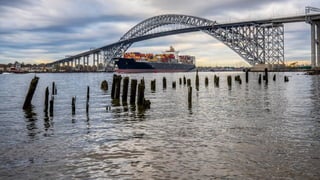
  • 10. 4.2.2 Through bridges A through arch bridge, also known as a half-through arch bridge or a through-type arch bridge, is a bridge that is made from materials such as steel or reinforced concrete, in which the base of an arch structure is below the deck but the top rises above it. Material: Steel Prepared by- Prof. Basweshwar S. J.
  • 11. 4.2.3 Semi-through bridges • A deck type bridge is the one in which the roadway/railway floor rests on the top of the supporting structures, while a through bridge is the one where the roadway/railway floor rests on the bottom of the main load supporting structure. • However, when the floor lies between the top and bottom of the main supporting structure, it is known as half through type bridge, semi-through bridge or pony bridge. Prepared by- Prof. Basweshwar S. J.
  • 12. 4.3.1 Introduction of Continuous bridges- • Continuous bridges are more economical but lack simplicity in the design procedure. • These structures have the relative advantage that their designs are simple and do not involve any complicated analysis but the main drawback is that such structures are generally comparatively costly. Continued… Prepared by- Prof. Basweshwar S. J.
  • 13. 4.3.1 Advantages and disadvantages of Continuous bridges- Advantages- (i) Unlike simply supported bridges, these structures require only one line of bearings over piers thus reducing the number of bearings in the superstructure as well as the width of the piers. (ii) Due to reduction in the width of pier, less obstruction to flow and as such possibility of less scour. (iii) Require less number of expansion joints due to which both the initial cost and the maintenance cost become less. The riding quality over the bridge is thus improved. (iv) Reduces depth at mid-span due to which vertical clearance or headroom is increased. This may bring down the bridge deck level reducing thereby not only the cost of the approaches but also the cost of substructure due to lesser height of piers and abutments which again reduces the cost of the foundation. (v) Better architectural appearance. Disadvantages- (i) Analysis is laborious and time consuming. (ii) Not suitable on yielding foundations. Differential settlement may cause undesirable stresses. Design Procedure of Continuous Bridges: 1. Fix up span lengths in the unit and select rough sections at mid-spans and at supports. 2. Select appropriate soffit curve. 3. Work out dead load moments at different sections etc. Prepared by- Prof. Basweshwar S. J.
  • 14. 4.3.2 Introduction of Cantilever bridges- • A cantilever bridge has the same function of any other bridge; to span obstacles to provide passage over it for pedestrians, vehicles or railways. • This type of bridge is selected when necessity supports cannot be provided at specific positions, due to the great straining actions. Continued… Prepared by- Prof. Basweshwar S. J.
  • 15. 4.3.2 Advantages and disadvantages of Cantilever bridges- Advantages- • Assembled sections of suspended bridges can only be elevated and attached between two cantilever spans. • Support are required on only one side of each cantilever. • The bridge floor might be simply formed into sections, which preserve uniformity and ensure high quality. • These bridges have multiple cantilever spans, construction can be started immediately from all its columns reducing the time required. • Navigation under the bridge is not interrupted during its construction. • In areas with a strong rock structure, anchor arms might be connected to the surrounding rock, without the necessity for synthetic support. • The span of those bridges is longer than conventional beams since the cantilever are attached at the ends of the bridge. Disadvantages- • Extensive analysis to prevent fatigue failure of elements and welds. • These are large-scale structures, which are complex to construct and maintain. • These bridges are heavy, cantilevers require must be bigger and stronger support columns. • They will not be suited for earthquake-prone areas or areas with low-rock stability. Design Procedure of Cantilever Bridges: 1. The cantilever bridge is different from simply supported structures. 2. Simply supported structures are directly supported at each end, whereas cantilevered structures are directly supported at one end and free at the other end etc. Prepared by- Prof. Basweshwar S. J.
  • 16. 4.3.3 Introduction of Arch bridges- • An arch bridge is a bridge with abutments at each end shaped as a curved arch. • Arch bridges work by transferring the weight of the bridge and its loads partially into a horizontal thrust restrained by the abutments at either side. • A viaduct (a long bridge) may be made from a series of arches, although other more economical structures are typically used today. Continued… Prepared by- Prof. Basweshwar S. J.
  • 17. 4.3.3 Advantages and disadvantages of Arch bridges- Advantages- • Provides a better level of resistance. • Design is good in terms of pressure. • An arch bridge is often made from stone, bricks or nearly the other natural material that has the standard of withstanding forces of compression. • Structurally sound. • The half-circle form of an arch bridge is by design designed to create certain that no distortion or injury would occur to the structure because of extreme pressure or weight. • Becomes stronger because it works. • Offers economic advantages. Disadvantages- • Restricted span:. • Constraints on the location. • Needs additional maintenance. • Needs additional support. • Will take long to build. • Pricey to build. Design Procedure of Arch Bridges: 1. Arch Analysis. 2. False work centering. 3. Deck raising. 4. Road development etc. Prepared by- Prof. Basweshwar S. J.
  • 18. 4.3.4 Introduction of Bow-string girder type bridges- • A tied-arch bridge is an arch bridge in which the outward-directed horizontal forces of the arch(es) are borne as tension by a chord tying the arch ends, rather than by the ground or the bridge foundations. • This strengthened chord may be the deck structure itself or consist of separate, deck-independent tie-rods. • Thrusts downwards on a tied-arch bridge deck are translated, as tension, by vertical ties between the deck and the arch, tending to flatten it and thereby to push its tips outward into the abutments, like for other arch bridges. Continued… Prepared by- Prof. Basweshwar S. J.
  • 19. 4.3.4 Advantages and disadvantages of Bow-string girder type bridges- Advantages- • It offers higher levels of resistance compared to other designs. • It offers the option to span a greater distance. • It can be construction from almost any material. • It provides an advantage when carrying loads. • It continues to provide support without distortion over time. • It can become stronger over time. • It adapts to local environmental conditions better. Disadvantages- • It offers a finite span length to use. • It is a time-consuming project to complete. • It is a structure which requires careful maintenance. • It is a bridge option that cannot be built in some locations. • It requires more side support to complete a successful span. • It requires expertise to build. Design Procedure of Bow-String girder Bridges: 1. Arch Analysis with end support loadings 2. False work centering. 3. Deck lifting 4. Road development etc. Prepared by- Prof. Basweshwar S. J.
  • 20. 4.3.5 Introduction of Rigid frame bridges- • A Rigid-frame bridge is a bridge in which the superstructure and substructure are rigidly connected to act as a continuous unit. • Typically, the structure is cast monolithically, making the structure continuous from deck to foundation. • The connections between members are rigid connections which transfer bending moment, axial forces, and shear forces. • A bridge design consisting of a rigid frame can provide significant structural benefits, but can also be difficult to design and/or construct. Continued… Prepared by- Prof. Basweshwar S. J.
  • 21. 4.3.5 Advantages and disadvantages of Rigid frame bridges- Advantages- • More rigidity of the structure. • Less moments in deck being partly transferred to the supporting members. • No bearings are required. Design Procedure of Rigid Frame Bridges: 1. Arch Analysis with end support loadings 2. False work centering. 3. Deck lifting 4. Road development etc. Disadvantages- • There are no built-in supports for beam bridges. • Span limitations exist for beam bridges. • Beam bridges can sometimes start to sag as they age. • There is little aesthetic value to consider with a beam bridge. • The cost of steel often dictates any price advantages which may be present. • Beam bridges can go through a significant amount of wear-and-tear in their lifetime. • Beam bridges do not offer a lot of flexibility. • Requires more on maintenance costs with beam bridges when compared to other designs. • The width of the deck span is limited with a beam bridge. Prepared by- Prof. Basweshwar S. J.
  • 22. 4.3.6 Introduction of Portal frame bridges- • Portal frames are generally designed for use below ground to provide waterways or pedestrian subways. • The units are supported on in situ concrete foundations. • Seals are provided between successive units to ensure a water-tight structure. • The dimensions of the units and their weights will be limited by the requirements for transportation and installation. • Similar units may be designed for use above ground to form integral bridge type structures or frames for building structures. Continued… Prepared by- Prof. Basweshwar S. J.
  • 23. 4.3.6 Advantages and disadvantages of Portal frame bridges- Advantages- • When compared to conventional bridges, construction costs and maintenance costs are much lower. • Construction of integral bridges is simple and rapid. • If new bridge is constructing in place of existing old bridge, the foundation of old bridge can be used as foundation for new bridge. Hence cost of project reduces. • Elimination of water leakage on critical structural elements can be done using drainage layer provided behind the integral abutments. • The vehicle riding quality on integral bridge is more comfortable and smooth since there are no expansion joints. Disadvantages- • These bridges are not suitable in zones where there is chance of expansion/contraction of more than 51mm during temperature variations. • They are not preferred when subsoil or embankments are of poor strength. • Geometry of the bridge and material used for the construction play key role in case of these bridges. • They are responsible for the displacement affects in the bridge. Design Procedure of Portal Frame Bridges: • Portal Frame Analysis with end moments • Casting. • Deck construction. • Road development etc.Prepared by- Prof. Basweshwar S. J.
  • 24. 4.3.7 Introduction of Suspension bridges- • A suspension bridge is a type of bridge in which the deck is hung below suspension cables on vertical suspenders. • The basic structural components of a suspension bridge system include stiffening girders/trusses, the main suspension cables, main towers, and the anchorages for the cables at each end of the bridge. • The main cables are suspended between towers and are finally connected to the anchorage or the bridge itself, and vertical suspenders carry the weight of the deck and the traffic load on it. Continued… Prepared by- Prof. Basweshwar S. J.
  • 25. 4.3.7 Advantages and disadvantages of Suspension bridges- Advantages- • Cost Effective. • Can Be Built High Up. • Span Great Lengths. • Simple Construction Disadvantages- • Soft Ground Issues • Too Flexible • Cannot Support High Traffic Design Procedure of Suspension Bridges: 1. Loading identification 2. Suspenders and span criteria 3. Suspender launching 4. Girder launching etc. Prepared by- Prof. Basweshwar S. J.
  • 26. • A cable-stayed bridge offers a design that is similar to a suspended bridge. • It will have towers that help to support the structure, while the deck is held in place by cables. • The difference in the design is that the cables hold the deck by connecting it directly to the support pillars instead of using suspending wires or cables to stabilize the span. • This bridge type is useful for numerous traffic options, including automobiles, trucks, bicycles, and pedestrians. • In some situations, a cable-stayed bridge is suitable for light rail as well. • Engineers use this option when a span must be longer than what a cantilever bridge can support because of its weight, yet it is also short enough so that a suspension bridge is not the most practical option. Continued… 4.3.8 Introduction of Cable-stayed bridges- Prepared by- Prof. Basweshwar S. J.
  • 27. 4.3.8 Advantages and disadvantages of Cable-stayed bridges- Advantages- • Cable-stayed bridges take less time to complete than other options. • The strength of a cable-stayed bridge is unquestionable. • It can be significantly cheaper to build a cable-stayed bridge. • Cable-stayed bridges can be constructed to almost any length. • There are multiple design options from which to choose with a cable-stayed bridge. • The design of the cable-stayed bridge supports itself. • Cable-stayed bridges offer the possibility of a symmetrical design. Disadvantages- • Cable-stayed bridges do have a maximum length to consider. • This design option can become unstable in specific environments. • Cable-stayed bridges can be challenging to inspect and repair. • It is a design that can sometimes be susceptible to rust or corrosion. • The strength advantages typically apply to short spans. Design Procedure of Cable- Stayed Bridges: • Loading Analysis • Aided software • Launch of Elements • Suspender checks etc.Prepared by- Prof. Basweshwar S. J.
  • 28. 4.3.8 Introduction of Composite bridges- • 'Composite' means that the steel structure of a bridge is fixed to the concrete structure of the deck so that the steel and concrete act together, so reducing deflections and increasing strength. • This is done using 'shear connectors' fixed to the steel beams and then embedded in the concrete. • Shear connectors can be welded on, perhaps using a 'stud welder', or better still on export work, by fixing nuts and bolts. • Usually the steel carries its own weight and that of the wet concrete. But when the concrete is 'cured' and has acquired its full strength, then all future loads (traffic, surfacing, wind, water, pressure, seismic loads) are shared by the steel/concrete composite. • The concrete is good in compression, while the steel is good in tension and compression. Continued… Prepared by- Prof. Basweshwar S. J.
  • 29. 4.3.8 Advantages and disadvantages of Composite bridges- Advantages- • High torsional stiffness and strength this enables the use of box girders in horizontally curved bridges and interchanges. • Greater aerodynamic stability; • Reduced susceptibility to lateral buckling of flanges in lateral-torsional and distortional buckling modes; • Support point required are less compared to conventional systems. • Improved durability. • Reduced maintenance of protective coatings since the exposed surface is less and fewer edges are there and avoidance of exposed horizontal surfaces, no exposed bracing and stiffeners; • Clean lines of a closed box girder provide better appearance for footbridges where the visual impact counts. Disadvantages- • Greater fabrication cost due to reduced scope for automated fabrication; • Handling during fabrication and coating is very difficult; • Greater design input; • Risks associated with working in enclosed spaces. Design Procedure of Composite Bridges: • Loading Analysis • Aided software • Launch of Elements • Combination checks in steel and concrete etc. Prepared by- Prof. Basweshwar S. J.
  • 31. 4.4 Materials for super-structures- • Some of the main typical materials that are found on a bridge are steel, concrete, stone and asphalt. • Other materials include iron, timber, aluminum, rubber and other joint materials. • Concrete is commonly used for many bridge superstructure members such as decks, pre-stressed concrete beams, curbs, sidewalks and parapets (side traffic barrier walls). • Steel is commonly used in the bridge superstructure for armoring expansion joints, beams, bearings, floor beams, girders, reinforcing bars in concrete, traffic barriers and trusses. • Stone was commonly used for building the abutments and piers in the 1940’s and earlier. • Asphalt is the material that has been used extensively for the wearing surfaces on corrugated metal decks, timber decks and concrete decks. • Iron was used typically in beams and trusses that were built before 1900. • Timber is used for several decks and traffic barriers. It is also used for the beams on one bridge and the abutments and piles on another bridge. • Aluminum is sometimes used in fabricating bridge railings. • Rubber and synthetic rubber products are used for bearings and for expansion joint material. Prepared by- Prof. Basweshwar S. J.
  • 32. 4.4.1 Cement concrete- • Concrete is a composite material composed of fine and coarse aggregate bonded together with a fluid cement (cement paste) that hardens (cures) over time. • In the past lime based cement binders were often used, such as lime putty, but sometimes with other hydraulic cements, such as a calcium aluminate cement or with Portland cement to form Portland cement concrete (named for its visual resemblance to Portland stone). • Many other non-cementitious types of concrete exist with other methods of binding aggregate together, including asphalt concrete with a bitumen binder, which is frequently used for road surfaces, and polymer concretes that use polymers as a binder. Prepared by- Prof. Basweshwar S. J.
  • 33. 4.4.2 Masonry- • A bridge whose main load-bearing structures are made of natural stone, brick, or concrete blocks. • Such a bridge is always arched, with massive supports. • The spandrel is made from a gravel or crushed stone backing held in by lateral (side) walls made of concrete masonry or stonework or in the form of an open structure of small arches resting on crosswalk. • The advantages of a masonry bridge are its architectural at-tractive ness and its durability. • Masonry bridges are known that have been in use for more than 1,000 years. • The basic shortcomings that limit the use of masonry bridges are their complexity and labor-intensiveness of construction. • A variation of a masonry bridge is the concrete bridge, which has an arch made of cast concrete. Prepared by- Prof. Basweshwar S. J.
  • 34. 4.4.3 Steel- • Steel is widely used around the world for the construction of bridges from the very large to the very small. • It is a versatile and effective material that provides efficient and sustainable solutions. • Steel has long been recognized as the economic option for a range of bridges. • It dominates the markets for long span bridges, railway bridges, footbridges, and medium span highway bridges. • It is now increasingly the choice for shorter span highway structures as well. • Steel bridges are an essential feature of a country’s infrastructure and landscape. • Few man-made structures combine the technical with the aesthetics in such an evocative way. Prepared by- Prof. Basweshwar S. J.
  • 35. 4.4.4 Timber • A timber bridge or wooden bridge is a bridge that uses timber or wood as its principal structural material. • One of the first forms of bridge, those of timber have been used since ancient times. • Recently timber bridges have received attention in the United States because they are environmentally friendly compared to other bridge types. Until 1991, the Federal Highway Administration has concentrated on major highways and other primary roads; rural highways and local roads, where timber bridges are mostly found, have received less attention. Prepared by- Prof. Basweshwar S. J.