Downloaded 172 times


![Analysis Types
DC Analysis
DC transfer curve source and sweep
.dc <source> <vstart> <vstop> <vincr> [src2 start2 stop2 incr2]
.DC VIN 0.25 5.0 0.25
AC Analysis
.AC DEC ND FSTART FSTOP
Dec = decade variation, ND = pts. / decade
.AC LIN NP FSTART FSTOP
Lin = linear variation, NP = # pts
.NOISE OUTV INSRC NUMS
OUTV = output voltage which defines summing point
INSRC = name of independent source which is the noise input
reference
NUMS = summary interval
Transient
(.tran <step> <stop> <start>)
Transient analysis computes the transient output variables as a function
of time over a user specified time interval
The initial conditions are automatically determined by a dc analysis
.tran 1ns 1000ns 500ns](https://image.slidesharecdn.com/pspiceseminar-141126071320-conversion-gate02/85/PSPICE-seminar-12-320.jpg)
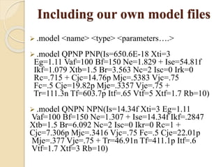
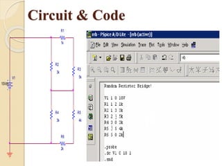


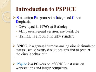
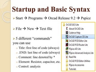
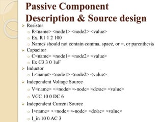
This document provides an overview of PSPICE, a circuit simulation software. It describes how PSPICE can be used to simulate analog circuits, analyze circuit behavior, and visualize output through graphical plots. Key features of PSPICE include its ability to simulate circuit components like resistors, capacitors, transistors, and operational amplifiers. It also allows various types of circuit analyses, including DC, AC, transient, and Fourier analyses. The document provides examples of basic PSPICE commands and syntax for defining circuit elements and performing simulations.