Spice is a software program used to simulate and analyze electrical and electronic circuits. It allows users to define circuit components and parameters in a netlist file and run various types of analyses, including DC, AC, and transient analyses. Key statements include titles, comments, data statements to define components, and control statements to specify the type of analysis and output.
This document provides a system block diagram and requirements for a NIST radiation pressure sensor. The block diagram shows the key components including a laser, spring, amplifier, and microcontroller used to measure small forces on a scale. The closed-loop requirements specify the controller must have a rise time less than 100ms, zero steady-state error to balance the bridge, and reject disturbances below 1kHz to prevent spring vibration. The microcontroller samples at 1.25us to control the system and meet the closed-loop performance goals.
This document describes how different linear controlled sources in Spectre are translated to ADS, including voltage controlled current sources (VCCS), voltage controlled voltage sources (VCVS), current controlled current sources (CCCS), and current controlled voltage sources (CCVS). Each source in Spectre (such as vccs, vcvs, cccs, ccvs) is translated to a corresponding device in ADS (VCCS, VCVS, SDD, SDD) along with examples of the command lines and netlist syntax for both simulators. Parameter mappings are also provided to understand how source parameters in Spectre translate to parameters in the equivalent ADS device.
This document provides specifications for an Advanced Power N-CHANNEL ENHANCEMENT MODE POWER MOSFET. It has a low on-resistance of 9mΩ, simple drive requirements, and fast switching characteristics with a continuous drain current of 57A. The MOSFET is RoHS compliant, halogen-free, and has a maximum drain-source voltage of 25V. It comes in the TO-252 surface mount package.
This document outlines welding procedure specification (WPS) and procedure qualification record (PQR) check list items for several welding processes including shielded metal arc welding (SMAW), gas metal arc welding (GMAW), flux-cored arc welding (FCAW), gas tungsten arc welding (GTAW), and submerged arc welding (SAW). It lists over 40 variables that must be specified on WPSs and recorded on PQRs, classifying them as essential, supplementary essential, or nonessential. Changes to essential variables require requalification of the WPS, while changes to supplementary or nonessential variables may not require requalification depending on whether impact testing was performed.
Original N-Channel Mosfet PFF7N80 800V 7A TO-220F New WING ON GROUPAUTHELECTRONIC
This document describes the PFP7N80/PFF7N80 800V N-channel MOSFETs from Wing On STS. Key specifications include a continuous drain current of 7A, on-resistance of 1.55Ω typical, and gate charge of 35nC typical. The document provides detailed electrical characteristics, thermal characteristics, application information, and test methodology for the devices.
This document discusses a dual slope analog to digital converter (ADC). It includes:
1) A block diagram showing the basic components of a dual slope ADC.
2) A circuit diagram of the dual slope ADC implementation.
3) An analysis of the time domain operation of the dual slope ADC.
This document provides an overview of PSPICE and how to use it to simulate analog circuits. It describes the different types of input files for PSPICE, how to define circuit components and models, and the various analysis statements like .OP, .DC, .AC, and .TRAN to set up DC operating point, DC sweep, AC, and transient analyses respectively. It also covers topics like subcircuits, semiconductor device models, and scale factors for numbers in PSPICE.
This document provides an overview of PSPICE, a circuit simulation software. It describes how PSPICE can be used to simulate analog circuits, analyze circuit behavior, and visualize output through graphical plots. Key features of PSPICE include its ability to simulate circuit components like resistors, capacitors, transistors, and operational amplifiers. It also allows various types of circuit analyses, including DC, AC, transient, and Fourier analyses. The document provides examples of basic PSPICE commands and syntax for defining circuit elements and performing simulations.
Original Mosfet MC33151DR2G 33151 MC33151 SOP-8 NewAUTHELECTRONIC
The MC34151 and MC33151 are dual high-speed MOSFET drivers designed to interface low current digital circuits with large capacitive loads. Each device contains two independent channels that can source or sink up to 1.5A. Key features include CMOS/LSTTL compatible inputs, 15ns rise/fall times with a 1000pF load, undervoltage lockout, and pin compatibility with similar drivers. Typical applications are in power supplies, DC-DC converters, and motor controllers.
Original N-Channel Mosfet 2SK3484 3484 16A 100V TO-252 New Renesas ElectronicsAUTHELECTRONIC
This document provides specifications for the 2SK3484 N-channel MOS field effect transistor (MOSFET) including:
- Electrical characteristics such as on-state resistance, gate cut-off voltage, and input/output capacitances.
- Thermal characteristics such as thermal resistance and power dissipation derating curves.
- Switching characteristics such as turn-on/off delay times and rise/fall times.
- Package drawings and equivalent circuit diagram for the TO-251 and TO-252 packages.
Original N - Channel Mosfet IRFR3709ZTRPBF FR3709Z 3709 FR3709 TO-252 New IRAUTHELECTRONIC
Original N - Channel Mosfet IRFR3709ZTRPBF FR3709Z 3709 FR3709 TO-252 New IR
https://authelectronic.com/original-n-channel-mosfet-irfr3709ztrpbf-fr3709z-3709-fr3709-to-252-new-ir
Original P Channel Mosfet IRF9Z34 IRF9Z34N IRF9Z34NPBF 9Z34 60V 18A TO 220 NewAUTHELECTRONIC
Original P Channel Mosfet IRF9Z34 IRF9Z34N IRF9Z34NPBF 9Z34 60V 18A TO 220 New
https://authelectronic.com/original-p-channel-mosfet-irf9z34-irf9z34n-irf9z34npbf-9z34-60v-18a-to-220-new
Original N-Channel Mosfet IRFI4019H-117P 4019 8A 150V TO-220 NewAUTHELECTRONIC
This document provides information on a digital audio MOSFET in a TO-220 Full-Pak 5 pin package designed for class D audio amplifier applications. The MOSFET integrates two power switches in a half-bridge configuration to reduce part count. Key parameters like low RDS(on), Qg, Qsw, and Qrr are optimized to improve efficiency, THD, and reduce EMI. Figures and tables of electrical characteristics like breakdown voltage, on-resistance, gate charge, and switching performance are provided. The document also includes test circuits and considerations for evaluating the MOSFET.
Original N-Channel Mosfet IRFI4019H-117P 4019 8A 150V TO-220 NewAUTHELECTRONIC
Original N-Channel Mosfet IRFI4019H-117P 4019 8A 150V TO-220 New
https://authelectronic.com/original-n-channel-mosfet-irfi4019h-117p-4019-8a-150v-to-220-new
Original N-channel 650 V 0.230 Ohm 12 A MDmesh V Power MOSFET in DPAK DPAK ST...AUTHELECTRONIC
Original N-channel 650 V 0.230 Ohm 12 A MDmesh V Power MOSFET in DPAK DPAK STF16N65M5 16N65M5 16N65 710V 12A TO-220FP New STMicroelectronics
https://authelectronic.com/original-n-channel-650-v-0-230-ohm-12-a-mdmesh-v-power-mosfet-in-dpak-dpak-stf16n65m5-16n65m5-16n65-710v-12a-to-220fp-new-stmicroelectronics
Original N P-CHANNEL ENHANCEMENT Mosfet AP4506GEH 4506GEH 4506 TO-252 New Adv...AUTHELECTRONIC
This document summarizes the specifications and characteristics of an Advanced Power N-channel and P-channel enhancement mode MOSFET. The MOSFET has a maximum drain-source voltage of 30V for the N-channel and -30V for the P-channel. It has low on-resistances of 24mΩ and 36mΩ respectively. Tables provide the thermal data and electrical characteristics for each channel including threshold voltages, leakage currents, capacitances, and switching times. Graphs show characteristics such as output curves, gate charge waveforms, and safe operating areas.
Design and implementation of cyclo converter for high frequency applicationscuashok07
This document presents a design and implementation of a 3-phase cyclo-converter for high frequency applications. It uses an H-bridge inverter to generate a constant voltage at an RLC load. MOSFETs are used as switching devices due to their high switching speed. The purpose is to convert low frequency AC to high frequency AC without switching losses. MATLAB Simulink and Keil software are used to simulate the power and control circuits respectively.
Original N Channel Mosfet PHP45N03LTA PHP45N03LT 45N03LTA 45N03 TO-220 NewAUTHELECTRONIC
Original N Channel Mosfet PHP45N03LTA PHP45N03LT 45N03LTA 45N03 TO-220 New
https://authelectronic.com/original-n-channel-mosfet-php45n03lta-php45n03lt-45n03lta-45n03-to-220-new
Original Mosfet N-Channel SVF740T 740 400V 10A TO-220 NewAUTHELECTRONIC
This document provides specifications for the SVF740T/F N-channel MOSFETs produced by Silan Microelectronics. Key details include:
- The SVF740T and SVF740F have maximum drain currents of 10A and 6.3A respectively, and maximum drain-source voltages of 400V.
- Electrical characteristics are provided such as a typical on-resistance of 0.45Ω and gate threshold voltage range of 2-4V.
- Thermal characteristics include a junction-to-case thermal resistance of 0.96°C/W for the SVF740T and 2.84°C/W for the SVF740F.
- Typical performance
This document provides information on the UC3844, UC3845, UC2844, and UC2845 high performance current mode controllers, including:
- Operating temperature ranges and packaging for the devices.
- Pin connections and ordering information for the different package types.
- Electrical characteristics like reference voltage, oscillator frequency, error amplifier performance, current sense input, output specifications, and undervoltage lockout thresholds.
- Graphs depicting properties like oscillator frequency vs timing resistor, output deadtime vs frequency, error amplifier gain and phase vs frequency, and more.
- An overview of key features like current mode operation, adjustable output deadtime, compensation, current limiting, undervoltage lockout,
This document provides information on dual operational amplifiers including the LM358, LM258, LM2904, and LM2904V. It includes maximum ratings, electrical characteristics, representative schematics, circuit descriptions, and example applications such as voltage references, oscillators, filters, and comparators. The amplifiers feature low power, rail-to-rail input/output, and compatibility with popular operational amplifiers.
Original Opto TLP620GB TLP620 P620 620 DIP-4 New ToshibaOriginal Opto TLP620G...authelectroniccom
This document summarizes specifications for the Toshiba TLP620, TLP620-2, and TLP620-4 photocouplers. The TLP620 consists of an infrared emitting diode optically coupled to a photo-transistor. The TLP620-2 has two isolated channels and the TLP620-4 has four channels. Key specifications include a collector-emitter voltage rating of 55V minimum, current transfer ratio of 50% minimum, and isolation voltage of 5000Vrms minimum. Electrical characteristics, isolation characteristics, switching times and derating curves are provided.
Original Opto TLP620GB TLP620 P620 620 DIP-4 New ToshibaOriginal Opto TLP620G...
nfc
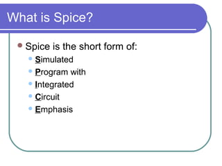
1. What is Spice?
Spice is the short form of:
Simulated
Program with
Integrated
Circuit
Emphasis
2. PSPICE Programming
Why PSPICE Programming
Steps of Programming
Statements
Data Statements
Control Statements
Example Circuits
3. Why PSPICE Programming
Don’t have to draw the circuit
More control over the parts
More control over the analysis
Don’t have to search for parts
Some SPICE softwares (HSPICE etc.)
don’t have GUI at all
Quick and efficient
4. Steps of Programming
Draw the circuit and label the nodes
Create netlist (*.cir) file
Add in control statements
Add in title, comment & end statements
Run PSPICE
Evaluate the results of the output
5. Statements
Different statements:
Not case sensitive
Title: first line of code (always)
.END <CR>: last line of code (always)
Comment: line denoted by *
Comment within a statement is preceded by a
semicolon (;)
+ means continuation of a sentence
Data: resistor, capacitor, etc.
Control: analysis and output
17. DC Analysis
PLOT I-V Characteristics of NMOS
VTO = +1V
KP = 30u
D
MOSFET I-V Characteristics G M1
ID
M1 1 2 0 0 NTYPE
.MODEL NTYPE NMOS(VTO=1 KP=30u)
Vgs 2 0 5
Vds 1 0 5
.PROBE S
.PRINT DC I(Vds)
.DC Vds 0 5 .5 Vgs 0 5 1
.END
18.
19.
20.
21. AC Analysis
Format
.AC <sweep type> <points value>
<start frequency> <end frequency>
<sweep type> is either LIN, OCT, or DEC
Example
.AC LIN 1 60Hz 600Hz
.AC LIN 11 100 200
.AC DEC 20 1Hz 10kHz
22. AC Analysis
60 Hz AC Circuit
Vs 1 0 AC 120V 0
Rg 1 2 0.5
Lg 2 3 3.183mH
Rm 3 4 16.0
Lm 4 0 31.83mH
Cx 3 0 132.8uF
.AC LIN 1 60 60
.PRINT AC VM(3) VP(3) IM(Rm) IP(Rm) IM(Cx) IP(Cx)
.END
23.
24.
25. AC Analysis
Second-Order High-Pass Filter
Vin 1 0 AC 10V
Rf 1 2 4.0
Cf 2 3 2.0uF
Lf 3 0 127uH
.AC DEC 20 100Hz 1MEG
.PROBE
.END