
Recommended
More Related Content
What's hot
What's hot (20)
Similar to Traction OHE 30.07.2019.ppt
Similar to Traction OHE 30.07.2019.ppt (20)
Recently uploaded
Recently uploaded (20)
Traction OHE 30.07.2019.ppt
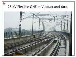
- 1. 25 KV Flexible OHE at Viaduct and Yard. 0
- 3. OHE ASSETS OF MAIN LINE Sr. No Item MANSAROVER TO SINDHI CAMP ROCS SECTION 1 Date of commissioning - - 2 Track KM 18.689246 529.854 3 Contect wire 23.627836 1.067 4 Massenger Wire 24.48162 - 5 OPC 19.54 1.13 6 BEC 19.36 1.13(TEW) 7 RC 18.5 1.13 8 IB 20 2 9 Cantilever 762 - 10 Section insulator 9 - 11 Cross Over 2 - 12 Gas ATD 36 (A-8,B-5,C-23) - 13 BWA ATD - - 14 Over lap 23(IOL-13, UIOL-10) 1(UIOL) 15 Turn Out 3 - 16 Isolator 10 - 17 8X8 Mast 470 - 18 B-series Mast(7.00) 102 - B-series Mast(8.50M) 10 - 19 PORTAL 9 - 20 RSJ 22 - 21 DA 80 80
- 4. OHE ASSETS OF DEPOT Sr.No. Item YBD 1 Date of commissioning - 2 Track KM - 3 Contect wire - 4 Massenger Wire - 5 OPC - 6 BEC - 7 RC - 8 ITL - 9 Cantilev er 295 10 Section insulator 27(galland11,rail 16) 11 Cross Ov er 1 12 Gas ATD 0 13 BWA ATD 28 14 Ov er lap 17(UIOL) 15 Turn Out 21 16 Isolator 19 (SS-15,DM-4) 17 8X 8 Mast 69 18 B-series Mast 39 19 Two Track Cantilev er 6(TTC) 20 portal BFBU 18 21 FP B-200 24 22 RSJ 8X 6 22 23 DA 6X 6 40 24 Earth Pit 71
- 5. OHE system adopted in JMRC • Cantilever Assembly • Mast & Implantation • Steady Arm & Encumbrance • Size of Contact wire and Tension in OHE. • Droppers and Jumpers. • ATD • Section Insulator • Neutral Section arrangement. • Earthing and Bonding • Return Conductor and Booster Transformer. • OHE Parameters, OHE Sectioning, OHE Spares and T&P, OHE Inspection & Maintenance Vehicles • OHE Inspection & Maintenance Schedules 4
- 6. STAY ARM Stay Arm comprises of dia 38 mm (Small) size tube and an adjuster at the end to keep the bracket tube in position. It is insulated from mast by stay arm insulator. Bracket tube comprises of dia 49 mm and insulated by bracket insulator. Catenary is supported from this member by catenary suspension bracket and catenary suspension clamp. Register arm comprises of dia 38 mm tube to register the contract wire in the desired position with the help of steady arm. Steady arm comprises of dia 25mm BFB section made of aluminium- alloy to register the contact wire to the required stagger and to take the push up of contact wire. It is always in tension. Bracket tube Register Arm •Steady arm.
- 7. ROCS in Tunnel and Underground Section. 6
- 8. ROCS Cantilever different Part 7
- 9. Transition element from Flexible to Rigid OHE The termination of the contact wire coming from the flexible catenary is terminated in the ROCS through a special come along clamp inserted on the last conductor rail
- 10. Details of Mast Used in JMRC SN Type of Mast Dimension Height Remarks 1 BFB ( Broad Flange Beam ) 8’’X8’’ 6.2 m Used in single cantilever location of viaduct 2 BFB ( Broad Flange Beam ) 8”X8” 9.5 m Used at Graded section / Depot. 3 RSJ (Rolled Steel Joist) 8”X6” 6.2 m Used at BT location 4 RSJ (Rolled Steel Joist) 8”X6” 9.5 m Used in Depot for mounting isolators. 5 B – 175 175X300 mm 6.2 m Multiple cantilever Location, Anchor location. 6 B – 200 200X300 mm 8.5 m Switching posts for cross feeders 9
- 11. Type of Mast
- 12. Implantation • The horizontal distance from the nearest face of traction mast to the centre line of the track . Track gauge =1435 mm • Centre of track = 717.5 mm Say 71.75 cm • hence put tape (non metallic) at 71.75 cm at inner edge of track & stretch till it reaches to the nearest face of the mast. The measured distance at face of the mast is implantation of the mast Centre Line of the Track Face of the Mast
- 13. Steady Arm • In JMRC bent steady arms are used for better performance in dynamic condition and it ensures better current collection at register point of cantilever. 12
- 14. Encumbrance • The axial distance on vertical plane between the Catenary and the contact wire at support the encumbrance shall normally be 0.90 M . Encumbrance
- 15. Size and tension of Contact and Catenary wire • Contact wire of 150 Sq mm hard drawn copper conductor is used in JMRC in contrary to 107 Sq mm Copper in IR. • The reason behind using of larger cross section area is that 1200 kgf tension is applied in both contact and catenary wire for better current collection. Whereas in Railways 1000 kgf tension is used. • The larger cross section area of contact wire also increases the breaking load of contact wire. 14 Contact Wire Splice Catenary Wire Splice
- 16. Droppers • In JMRC 12 mm bronze flexible cables used as droppes in contrary to 5 mm hard copper wire with loops in Indian Railways. • The risk of dropper breakage due to sparking in loops in IR has been resolved by using flexible crimped type droppers in JMRC. 15
- 18. Jumpers • Fit and Forget Type of Jumpers used in OHE to maintain electrical continuity and ensure equi potential within spans, across insulated overlaps, crossovers and in the sectioning posts. • The advantage of crimped jumper is that it ensures good contact thereby reducing contact resistance in turn reducing the chances of localize heating. Less maintenance is required. 17
- 20. In span jumpers • In JMRC 26 sq mm, in span jumpers are provided in every 200 m between contact and catenary for current distribution in contrary to 65 sq mm, jumpers in every 350 m in Indian Railway. • By increasing no. of jumpers in each tension length the distribution of current between Contact and Catenary improves. 19
- 21. In span jumpers in JMRC 20
- 22. Regulating Equipment (ATD) • • A device for maintaining the tension of OHE conductors constant under all ambient temperature conditions. It has two type. • 1. Balance weight type • 2. Gas type 5 PULLEY TYPE Balance weight ATD
- 23. Gas type ATD For critical locations where sufficient room is not available for counter weight installation , Due to less travelling distance available for movement of counter weight and to avoid falling of weight on road due to snapping of rope, Gas Type ATDs are used in JMRC Gas Type ATD is proposed to be used. In gas tensioners (Gas ATD) regulation is achieved by cylinder piston arrangement filled with the pressurized Nitrogen (N2) gas. In this arrangement piston is fixed on mast and cylinder is movable and is connected to OHE wires. Three type of Gas ATD’s are available as per half tension length. Total 41 nos GATD are in service in JMRC A) Type ‘A’ - Suitable for tension length up to 297 m b) Type ‘B’ - Suitable for tension length up to 468 m c) Type ‘C’ - Suitable for tension length up to 721 m
- 24. Construction and working of GATD 23
- 25. Section insulators • In JMRC light weight section insulators are installed to achieve spark less current collection in high speed and can be used in main lines. In Indian Railway generally heavy section insulators are used in only crossovers. • Provision of SI in main line give the flexibility for installing switching posts at will. 24
- 26. Section insulators in JMRC 25
- 27. Neutral Section • In JMRC magnets are used at before and after of Neutral Section for proper opening and closing of VCB’s before and after neutral section. In Indian Railways driver of the trains normally opened the VCBs at DJ open board location. • NSCZ boards also provided to rescue the trains in case of train stuck at neutral section. 26
- 28. 27
- 30. SHORT NS
- 31. Design of NS(AF design) R B
- 32. • PTFE rod gives larger Air gap causing almost no chance of wrong phase coupling. This reduces chance of damage to NS and pantograph both. • Mid point earthing further minimises coupling of two different phases. Advantages of Short Neutral sections
- 33. Earthing & Bonding System • All viaduct is non conducting concrete structure. Hence, special earthing arrangement has been provided. • Overhead Protection Cable (OPC) on top of OHE network and Buried Earth Cable (BEC) along track are run to provide complete earthing. All masts are connected with OPC.
- 34. Earthing & Bonding System • Every pier is provided with a non structural earthing bar (T-20). Earthing terminal is provided at the top of earthing bar. • All segments and track plinths are interconnected through jumpers. • Plinth Jumpers are connected to Buried Earth Conductor at every 100 meter.
- 35. 34
- 36. 35
- 37. Return Current and Booster Transformer Simple 1x25 kV ac traction systems can produce inductive interference in telecom lines and other equipment. Booster transformer system reduces that inductive interference.
- 38. Return Current and Booster Transformer Single system (ST): Return current system made by rails and buried earthing cable (if it exists). • The overhead catenary is fed electricity at 25kV AC (single-phase) from traction substations which are positioned at frequent intervals alongside the track. Current supplied by substations flows through catenary to the rolling stock and returns through rails. In some cases, this system also uses one buried earthing cable located along the track and connected to the rails at regular intervals. In this way, return system is made by rails and buried earthing cable.
- 39. Return Current and Booster Transformer Booster Transformer (BT) System: Return conductor close and parallel catenary wire. Return conductor is connected to the rails. • In this system there is a return conductor that is close to and parallel to the catenary wire. • Return conductor is connected to the rails (and earthed). • Periodically (every 2.5 km), there are breaks in the catenary where the supply current is forced to flow through one winding of a booster transformer. The other winding is in series with the return conductor. The 1:1 turn ratio of the BT means that the current in the catenary will be very nearly the same as the current in the return conductor. • Current that flows through the rolling stock goes to the rails but then up through a connecting wire to the return conductor and through it back to the substation. • Insulated rail joints are also provided -- this ensures that current flows in the rails only in the particular section where the train is present. At all other places, the inductive interference from the catenary current is nearly cancelled by that from the return current, thus minimizing the interference effects. The problem of stray earth currents is also reduced.
- 40. Return Current and Booster Transformer
- 41. • A special rail bond used to bridge an insulated rail joint in ac track circuited sections in areas equipped for electric traction .
- 42. Parameters of OHE in JMRC SN Items Values 1 Height ( Elevated ) 5 m No Variation 2 Height ( Under Ground ) 4.318 m No Variation 3 Stagger (Straight) +/- 200 mm No Variation 4 Stagger (Curve) +/- 300 mm No Variation 5 Min. Clearance betw live parts and structure (UG) 270 mm (Long time) 170 mm ( Short time ) Within limit 6 Min. Clearance betw live parts and Bodies of vehicle (UG) 290 mm ( Long Time ) 190 mm ( Short Time ) Within limit 7 Min. Vertical Clearance betw live parts and Earthed structure or Bodies of vehicle (Elevated) 320 mm ( Long Time ) 270 mm ( Short Time ) Within limit 8 Min. Lateral Clearance betw live parts and Earthed structure or Bodies of vehicle (Elevated) 320 mm ( Long Time ) 220 mm ( Short Time ) Within limit 41
- 43. Sectioning of OHE SN Type Quantity Location 1 Total RKM 9.7 km ( El -9.438 km, UG – 0.262 KM ) 2 Elementary Section 14 1 Sub Sectioning (SS) 2 Mansaovar, Sindhi Camp 2 Sub Sectioning and Paralleling (SSP) 1 Vivek vihar 3 Feeding Post (FP) 3 Mansarovar, Depot, Sindhi camp 4 Sectioning and Paralleling (SP) 1 Civil lines. 42
- 44. Spares and T&P for OHE maintenance SN Wing Major spares Major T&P Additional requirement 1 OHE All OHE spares like different types of conductor, jumpers, cantilever assemblies, Isolators, Masts, SIs, etc. already procured by JMRC. T&P items like Earth tester, multimeters, Tirfors, pull lifts, meggars, tool boxes, crimping tools, slings, D- sackles, discharge rods, safety belts, helmets, Contact wire dia measuring devices, height and stagger gauges etc already procured by JMRC. Some items which was left out in contract like Gas ATD, BWA ATD, Short neutral Section, PG clamps, all nut bolts etc and few spares and T&P’s felt less in quantity in contract are under procurement. 43
- 45. Maintenance and Inspection Vehicles Tower Wagon Emergency Vehicle
- 46. OHE Inspection & Maintenance SN Activity Schedule Checking points 1 Foot Patrolling Fortnightly Foundation ( At Grade ) OHE mast and portals Anchor Bracket Assembly Section insulator Regulating Assembly OHE Span Isolator RC & BT Earthing 2 Section Insulator Monthly Cleaning of core insulators Tightness of all nuts and bolts Checking of Runners Panto movement checking and balancing 3 Neutral Section Monthly Cleaning of PTFE rod. Checking of Runners Checking of balancing
- 47. OHE Inspection & Maintenance SN Activity Schedule Checking points 3 Section Insulator ( Other than Polluted Zone ) Quarterly Cleaning of core insulators Tightness of all nuts and bolts Checking of Runners Panto movement checking and balancing 4 Gas ATD Half Yearly Tightness of all nuts and bolts Measurement of X value and ramp extension Cleaning of Ramp Checking of Gas pressure. 5 BWA ATD Half Yearly Free movement of balance weight Greasing if required Checking of SS rope Measurement of X-Y value and adjustment if required. 6 Current collection Half yearly The points detected during current collection to be attended on priority basis.
- 48. OHE Inspection & Maintenance SN Activity Schedule Checking points 7 ST ,BT Insulator Half Yearly Cleaning of ST, BT insulator of polluted zone. 8 Cross over/TO Yearly Checking of height and stagger of mainline OHE and T/O OHE. Checking of sag in section insulator Panto movement checking Check bracket of obligatory mast. 9 Overlap Yearly Check height and stagger of IR and OR. Check clearance of OHE. Check jumper and PG Check panto movement. 10 Cantilever Yearly Check and tight all nut bolt. Cleaning of insulator. Measurement of height and stagger.
- 49. OHE Inspection & Maintenance SN Activity Schedule Checking points 11 Contact wire dia measurement yearly Contact wire dia should be taken in different locations where wear rate is high. A register to be maintained to check wear rate. Marking to be done on locations for future reference. 12 Tree trimming Yearly Every year in January joint inspection to be carried out with P Way to identify the trees nearby OHE. 13 Kite, Thread / Bird nest removal Yearly Should be attended on priority basis as observed during Foot plating and patrolling. With special emphasize in bird nesting season from April to September
- 50. OHE Inspection & Maintenance SN Activity Schedule Checking points 14 POH 4.5 yr Cantilever : One complete cantilever in identified polluted zone is to be replaced and its thorough cleaning and detailed examination is done of its moving parts for free movement and its rusted parts to take decision for level of maintenance. Check all the Cantilever component for cracks, rust and thread damage with a magnifying glass. The crack fittings and damage threads fittings should be discarded. Deteriorated GI fittings and pipes should be repaired by using cold galvanized paint. ATD : All regulating equipment(ATD) should be replaced with the overhauled ATD. SS rope should be closely examined for any damage to its strands. Ends of SS rope is also to be reversed. X & Y values to be adjusted as per temperature chart either by wire cutting or by adjuster. Removed ATD is to be taken to workshop and petrol cleaned and check for any rubbing mark on pulley block, if any replacement to be done. All lubricating holes should be free for passage of grease. Check for free movement of bearing of pulley block. Grease should be applied in the bearing by grease gun.
- 51. OHE Inspection & Maintenance SN Activity Schedule Checking points 14 POH 4.5 yr Jumpers: Dismantle all jumper connections. Check for broken/ damage strands. Overheating or corrosion specially at suspension clamps & BM flange connection. Contact and Catenary :a) Dismantle all Jumper connections b) Clean the conductors by emery paper, if there is a sign of over heating. c) Remove kink, if noticed d) Check the height and gradient of contact wire.
- 52. Inspection Schedule of Officers of OHE installation Inspection Supervisor Manager DGM GM ED Foot patrolling (full section) Monthly Quarterly 6 monthly Yearly As & when required OHE Gang (each gang) With gang Monthly Quarterly 6 monthly Yearly Cab/ Foot plate Daily Weekly Monthly Quarterly 6 Monthly Tower Wagon Fortnightly Monthly Quarterly 6 monthly Yearly Emergency vehicle Fortnightly Monthly Quarterly 6 monthly Yearly OHE Depot Fortnightly Monthly Quarterly 6 monthly Yearly Current Collection 6 monthly 6 monthly Yearly Yearly As and when required 51