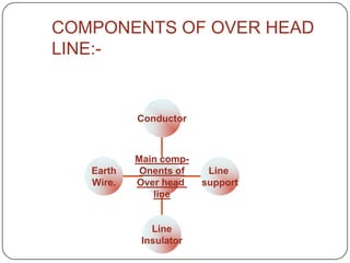
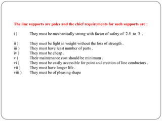
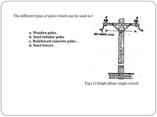
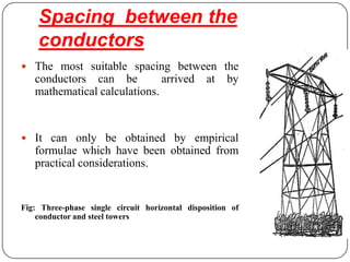
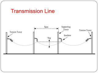
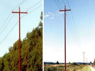
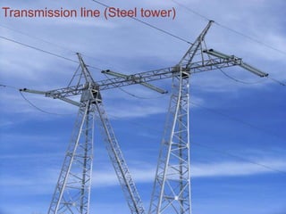
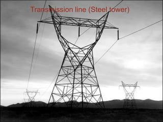
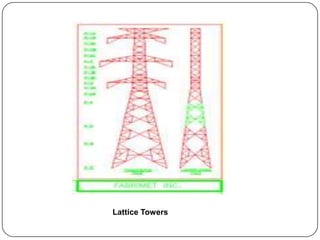
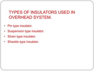
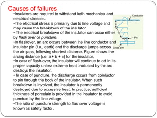
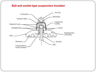
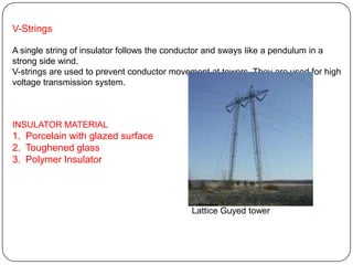
TRANSMISSION LINE

     SUMBUL.H.ABIDI
 ELECTRICAL DEPARTMENT
         S.P.C.E.
COMPONENTS OF OVER HEAD
LINE:-


           Conductor


           Main comp-
   Earth    Onents of    Line
   Wire.   Over head    support
              line


              Line
            Insulator
The line supports are poles and the chief requirements for such supports are :

i)       They must be mechanically strong with factor of safety of 2.5 to 3 .

ii )     They must be light in weight without the loss of strength .
iii )    They must have least number of parts .
iv )     They must be cheap .
v)       Their maintenance cost should be minimum .
vi )     They must be easily accessible for point and erection of line conductors .
vii )    They must have longer life .
viii )   They must be of pleasing shape
The different types of poles which can be used as line supports are :


          a. Wooden poles .
          b. Steel tubular poles
          c. Reinforced concrete poles .
          d. Steel towers .


                                              Fig.(1):Single phase single-circuit
Spacing between the
    conductors
 The most suitable spacing between the
   conductors can be          arrived           at   by
   mathematical calculations.


 It can only be obtained by empirical
   formulae which have been obtained from
   practical considerations.


Fig: Three-phase single circuit horizontal disposition of
    conductor and steel towers
Generally the following formulae are used for obtaining
   spacing between the conductors :

                            V
Spacing=            S
                           150
  Where,

  S=sag in meters

  V=voltage in KV
Transmission Line

                Span     Supporting
                           Tower       Tension Tower
Tension Tower
                           Insulator
                   Sag
Wooden Poles
•Cheapest
•Use for lines where span is short and tension is low.
•Pole has limitation of height and diameter.
•Wood has natural insulating property and lesser flashover
takes place due          to lightning.
•For greater strength double pole structure of ‘A’ or ‘H’ are
used.

Concrete Poles
•Concrete poles are reinforced to give greater strength.
•It has longer life span than that of wood
•The maintenance cost is less.
•They are heavy and are likely to get damage
duringloading,unloading,transportation and erection due to
their brittle nature.
•Nowadays pre-stressed concrete supports are
manufactured in pieces.
Steel poles
•Tubular steel poles or girder steel masts is favored for low and medium
distribution    voltages.
•Longer span is possible.
•Poles need to be galvanized or painted periodically to prevent corrosion.
•Maintenance is expensive.

Steel Towers
•Lines of 66 KV are supported on towers.
•They fabricated from painted or galvanized angle section which are
transported separately and erection done on site.
•Long life and high degree of reliability
•They can withstand severe weather conditions.
•The height of the towers depend on operating voltage and span length.
•The leg of the tower are set on concrete foundation
Types of steel towers
1. Tangent towers
•   They are used for straight runs.
•   Stress is due to weight of line,wind and ice load.
•   Extra forces due to break in the line on one side.
•   Base is either square or rectangle.
•   Suspension type insulators used.

2. Deviation tower
• They are used where transmission line changes
    direction.
• They have broader base , stronger members and
    are costlier
• Strain insulators are used.
They are classified
i.    Small angle towers(2o-15ochange in direction)
ii.    Medium angle towers(15o-30ochange in
      direction)
iii. Large angle towers(30o-60ochange in direction)
Transmission line (Steel tower)
Lattice Towers
TYPES OF INSULATORS USED IN
   OVERHEAD SYSTEM.
• Pin type insulator.
• Suspension type insulator.
• Strain type insulator.
• Shackle type insulator.
PIN INSULATORS


The pin type insulator is secured to the cross-arm on the pole. There is
a groove on the upper end of the insulator for housing the conductor.
The conductor passes through this groove and is bound by the
annealed wire of the same material as the conductor.

Pin type insulators are used for transmission and distribution of electric
power at voltages up to 33 kV. Beyond operating voltage of 33 kV, the
pin type insulators become too bulky and hence uneconomical.
Causes of failures
 •Insulators are required to withstand both mechanical and
 electrical stresses.
 •The electrical stress is primarily due to line voltage and
 may cause the breakdown of the insulator.
 • The electrical breakdown of the insulator can occur either
 by flash over or puncture.
 •In flashover, an arc occurs between the line conductor and
 insulator pin (i.e., earth) and the discharge jumps across
 the air gaps, following shortest distance. Figure shows the
 arcing distance (i.e. a + b + c) for the insulator.
 •In case of flash-over, the insulator will continue to act in its
 proper capacity unless extreme heat produced by the arc
 destroys the insulator.
 • In case of puncture, the discharge occurs from conductor
 to pin through the body of the insulator. When such
 breakdown is involved, the insulator is permanently
 destroyed due to excessive heat. In practice, sufficient
 thickness of porcelain is provided in the insulator to avoid
 puncture by the line voltage.
 •The ratio of puncture strength to flashover voltage is
 known as safety factor .
Ball and socket type suspension insulator

                                     Iron Cap
                  Locking Key
                                  Ball Socket
          Insulator's Head
                                    Compression
Expansion Layer                     Loading

   Imbedded Sand                           Cement

                                                     Insulating Glass
                                                     or Porcelain
Skirt


        Petticoats                       Steel Pin
                                  Ball
        Corrosion Sleeve
        for DC Insulators
Number of Insulators per
                          String
Line Voltage

   69 kV                 4–6


  115 kV                 7–9


  138 kV                8–10


  230 kV                 12


  345 kV                 18


  500 kV                 24


  765 kV                30–35
ADVANTAGES

•Each unit is designed for operating voltage of about 11KV .
•The string is free to swing in any direction.
•It is designed for longer span and higher mechanical loading.
•There is decreased liability to lightning disturbance if the
string is suspended from a metallic structure, which work as
lightning shield.


DISADVANTAGES
•Spacing between conductor is increased
•Height of tower increases
•Cost is high.
Strain or Tension Insulator
•Strain or tension insulators are designed for handling mechanical stresses at angle
positions where there is a change in the direction of the line at termination of line.
•Suspension insulator are arranged in a horizontal position. They are used to handle
mechanical stresses and take the pressure off a conductor at the end of a
transmission line, at a sharp corner or curve or over long river crossings.
•Strain insulators are typically used for higher voltage transmissions.

Shackle Type Insulators

•Shackle type insulators, similar to strain type insulators, are used on sharp curves,
end poles and in section poles.
•However, unlike strain insulators, shackle insulators are designed to support lower
voltages. These insulators are single, round porcelain parts that are mounted
horizontally or vertically.
V-Strings

A single string of insulator follows the conductor and sways like a pendulum in a
strong side wind.
V-strings are used to prevent conductor movement at towers. They are used for high
voltage transmission system.


INSULATOR MATERIAL
1. Porcelain with glazed surface
2. Toughened glass
3. Polymer Insulator


                                            Lattice Guyed tower
Presentation1

Presentation1

  • 1.
    TRANSMISSION LINE SUMBUL.H.ABIDI ELECTRICAL DEPARTMENT S.P.C.E.
  • 2.
    COMPONENTS OF OVERHEAD LINE:- Conductor Main comp- Earth Onents of Line Wire. Over head support line Line Insulator
  • 3.
    The line supportsare poles and the chief requirements for such supports are : i) They must be mechanically strong with factor of safety of 2.5 to 3 . ii ) They must be light in weight without the loss of strength . iii ) They must have least number of parts . iv ) They must be cheap . v) Their maintenance cost should be minimum . vi ) They must be easily accessible for point and erection of line conductors . vii ) They must have longer life . viii ) They must be of pleasing shape
  • 4.
    The different typesof poles which can be used as line supports are : a. Wooden poles . b. Steel tubular poles c. Reinforced concrete poles . d. Steel towers . Fig.(1):Single phase single-circuit
  • 5.
    Spacing between the conductors  The most suitable spacing between the conductors can be arrived at by mathematical calculations.  It can only be obtained by empirical formulae which have been obtained from practical considerations. Fig: Three-phase single circuit horizontal disposition of conductor and steel towers
  • 6.
    Generally the followingformulae are used for obtaining spacing between the conductors : V Spacing= S 150 Where, S=sag in meters V=voltage in KV
  • 7.
    Transmission Line Span Supporting Tower Tension Tower Tension Tower Insulator Sag
  • 8.
    Wooden Poles •Cheapest •Use forlines where span is short and tension is low. •Pole has limitation of height and diameter. •Wood has natural insulating property and lesser flashover takes place due to lightning. •For greater strength double pole structure of ‘A’ or ‘H’ are used. Concrete Poles •Concrete poles are reinforced to give greater strength. •It has longer life span than that of wood •The maintenance cost is less. •They are heavy and are likely to get damage duringloading,unloading,transportation and erection due to their brittle nature. •Nowadays pre-stressed concrete supports are manufactured in pieces.
  • 9.
    Steel poles •Tubular steelpoles or girder steel masts is favored for low and medium distribution voltages. •Longer span is possible. •Poles need to be galvanized or painted periodically to prevent corrosion. •Maintenance is expensive. Steel Towers •Lines of 66 KV are supported on towers. •They fabricated from painted or galvanized angle section which are transported separately and erection done on site. •Long life and high degree of reliability •They can withstand severe weather conditions. •The height of the towers depend on operating voltage and span length. •The leg of the tower are set on concrete foundation
  • 10.
    Types of steeltowers 1. Tangent towers • They are used for straight runs. • Stress is due to weight of line,wind and ice load. • Extra forces due to break in the line on one side. • Base is either square or rectangle. • Suspension type insulators used. 2. Deviation tower • They are used where transmission line changes direction. • They have broader base , stronger members and are costlier • Strain insulators are used. They are classified i. Small angle towers(2o-15ochange in direction) ii. Medium angle towers(15o-30ochange in direction) iii. Large angle towers(30o-60ochange in direction)
  • 12.
  • 13.
  • 14.
  • 15.
    TYPES OF INSULATORSUSED IN OVERHEAD SYSTEM. • Pin type insulator. • Suspension type insulator. • Strain type insulator. • Shackle type insulator.
  • 16.
    PIN INSULATORS The pintype insulator is secured to the cross-arm on the pole. There is a groove on the upper end of the insulator for housing the conductor. The conductor passes through this groove and is bound by the annealed wire of the same material as the conductor. Pin type insulators are used for transmission and distribution of electric power at voltages up to 33 kV. Beyond operating voltage of 33 kV, the pin type insulators become too bulky and hence uneconomical.
  • 17.
    Causes of failures •Insulators are required to withstand both mechanical and electrical stresses. •The electrical stress is primarily due to line voltage and may cause the breakdown of the insulator. • The electrical breakdown of the insulator can occur either by flash over or puncture. •In flashover, an arc occurs between the line conductor and insulator pin (i.e., earth) and the discharge jumps across the air gaps, following shortest distance. Figure shows the arcing distance (i.e. a + b + c) for the insulator. •In case of flash-over, the insulator will continue to act in its proper capacity unless extreme heat produced by the arc destroys the insulator. • In case of puncture, the discharge occurs from conductor to pin through the body of the insulator. When such breakdown is involved, the insulator is permanently destroyed due to excessive heat. In practice, sufficient thickness of porcelain is provided in the insulator to avoid puncture by the line voltage. •The ratio of puncture strength to flashover voltage is known as safety factor .
  • 19.
    Ball and sockettype suspension insulator Iron Cap Locking Key Ball Socket Insulator's Head Compression Expansion Layer Loading Imbedded Sand Cement Insulating Glass or Porcelain Skirt Petticoats Steel Pin Ball Corrosion Sleeve for DC Insulators
  • 20.
    Number of Insulatorsper String Line Voltage 69 kV 4–6 115 kV 7–9 138 kV 8–10 230 kV 12 345 kV 18 500 kV 24 765 kV 30–35
  • 21.
    ADVANTAGES •Each unit isdesigned for operating voltage of about 11KV . •The string is free to swing in any direction. •It is designed for longer span and higher mechanical loading. •There is decreased liability to lightning disturbance if the string is suspended from a metallic structure, which work as lightning shield. DISADVANTAGES •Spacing between conductor is increased •Height of tower increases •Cost is high.
  • 22.
    Strain or TensionInsulator •Strain or tension insulators are designed for handling mechanical stresses at angle positions where there is a change in the direction of the line at termination of line. •Suspension insulator are arranged in a horizontal position. They are used to handle mechanical stresses and take the pressure off a conductor at the end of a transmission line, at a sharp corner or curve or over long river crossings. •Strain insulators are typically used for higher voltage transmissions. Shackle Type Insulators •Shackle type insulators, similar to strain type insulators, are used on sharp curves, end poles and in section poles. •However, unlike strain insulators, shackle insulators are designed to support lower voltages. These insulators are single, round porcelain parts that are mounted horizontally or vertically.
  • 23.
    V-Strings A single stringof insulator follows the conductor and sways like a pendulum in a strong side wind. V-strings are used to prevent conductor movement at towers. They are used for high voltage transmission system. INSULATOR MATERIAL 1. Porcelain with glazed surface 2. Toughened glass 3. Polymer Insulator Lattice Guyed tower

Editor's Notes

  • #15 Transmission line steel tower
  • #26 Suitable for single cktline,right of way.spacing cross arm length size of tower .cost,L Xl (Dm)etc reduces