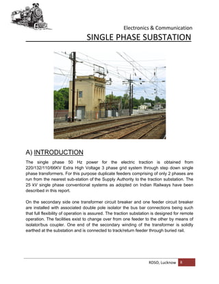
This document is a training report on Indian Railways, specifically detailing the author's experience during a summer training at the Research Designs & Standards Organisation (RDSO) in Lucknow. It outlines the organization’s history, functions, and the electrical systems used for electric locomotives on Indian Railways. The report also describes various aspects of electric traction, including supply systems, types of substations, and the technical equipment involved in railway operations.

![Electronics & Communication
RDSO, Lucknow 10
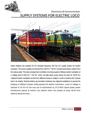
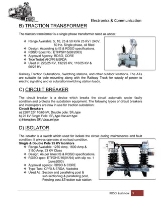
Overview Of Traction Offerings
[1] Traction transformer
[2] Traction converter
[3] Traction control
[4] Train Control and Monitoring System
[5] Traction motor
[6] Diesel engine generator
[7] Auxiliary converter
[8] Battery charger
[9] Energy storage](https://image.slidesharecdn.com/rdsoreport-200620104015/85/RDSO-Indian-Railways-Industrial-Training-Report-10-320.jpg)