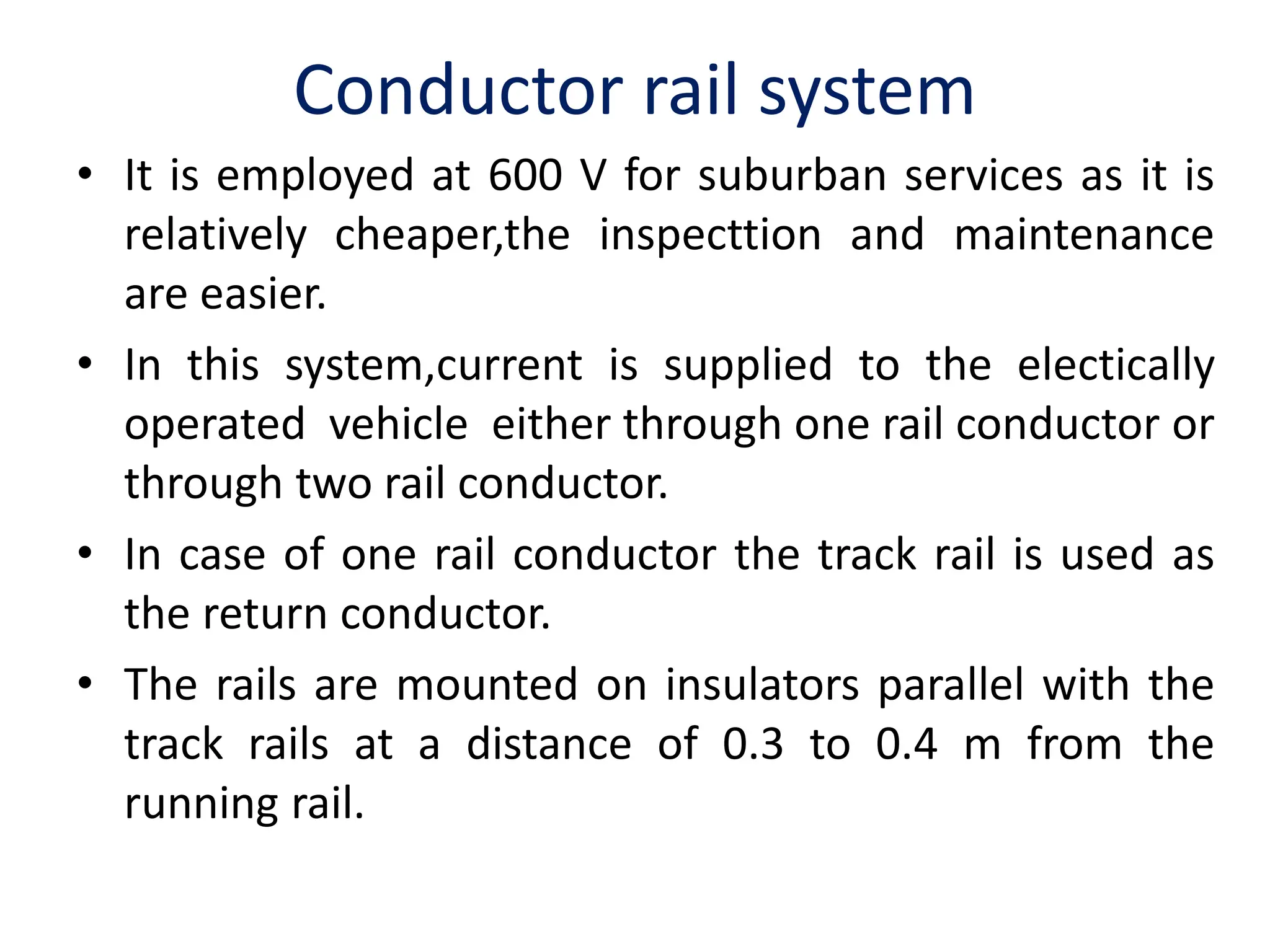
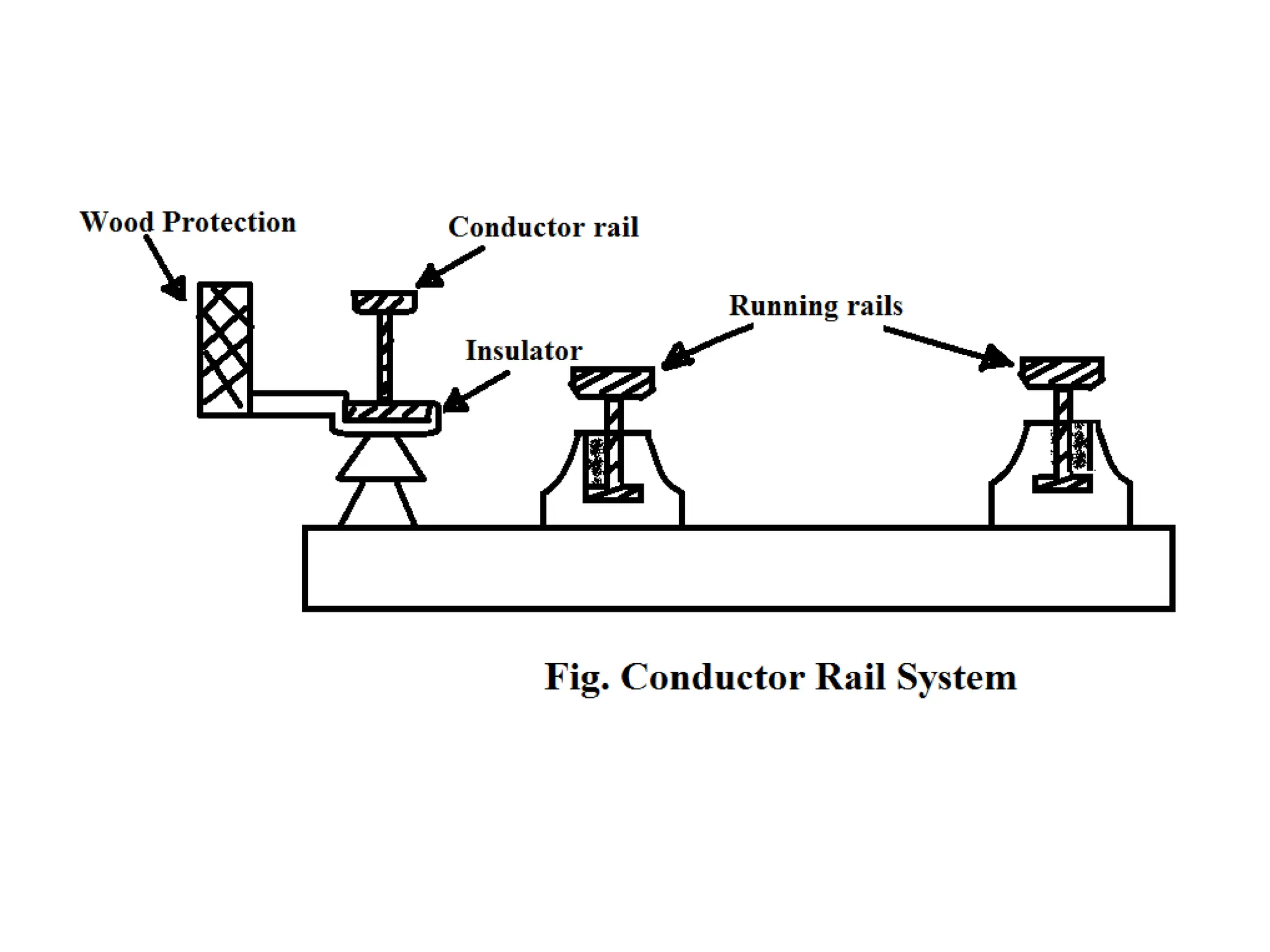
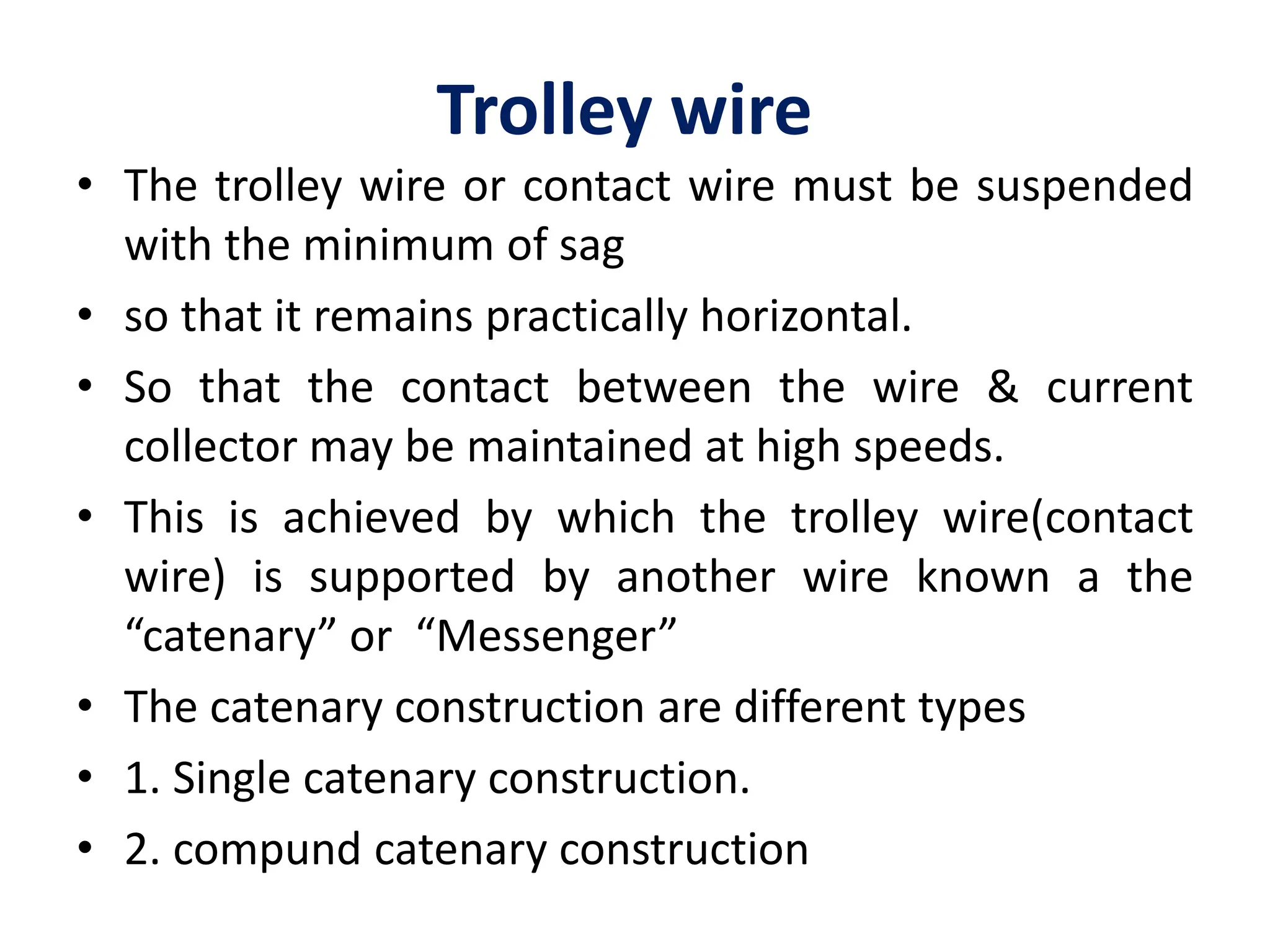
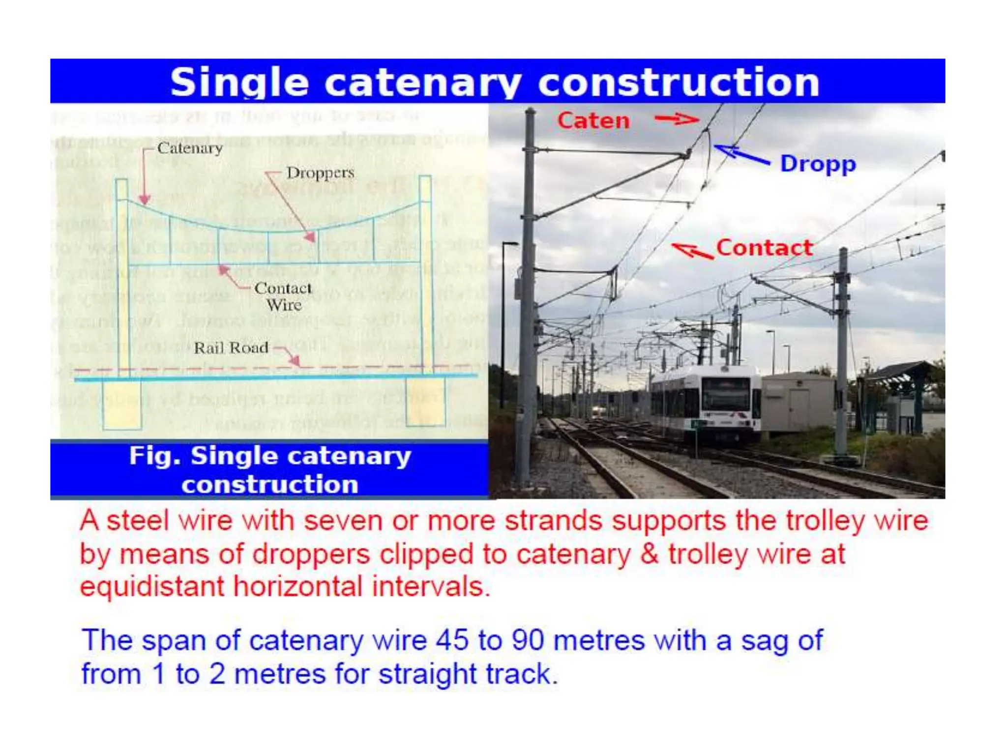
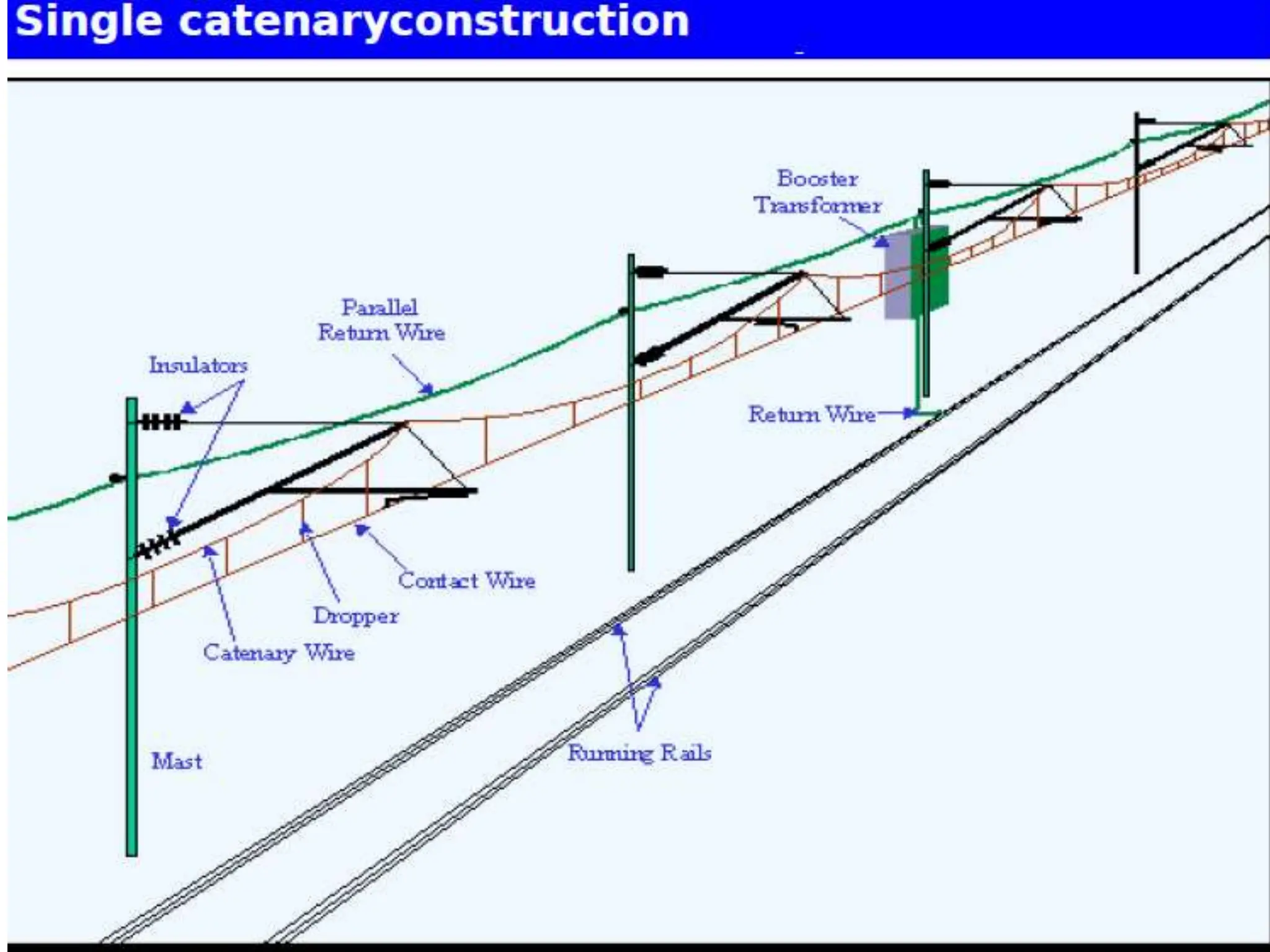
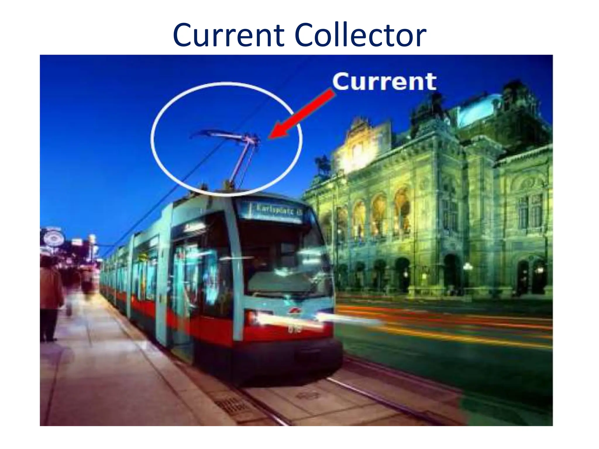
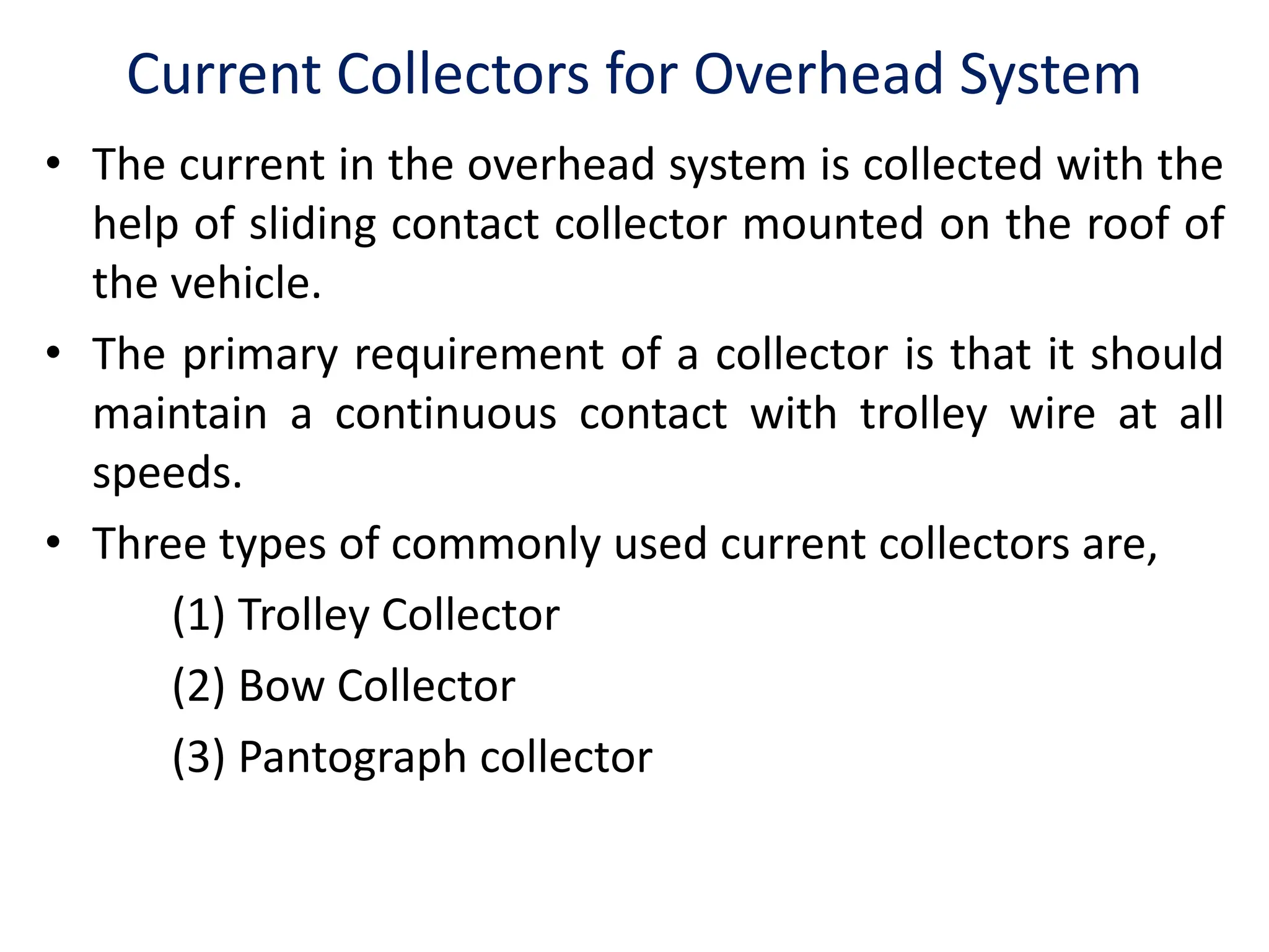
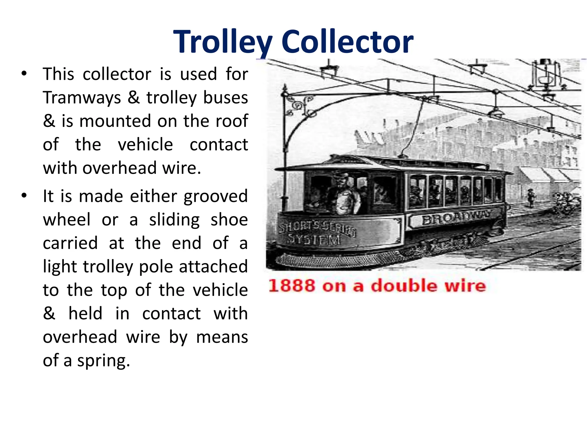
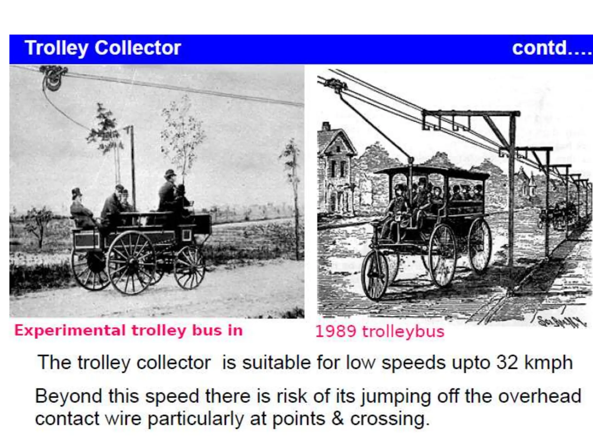
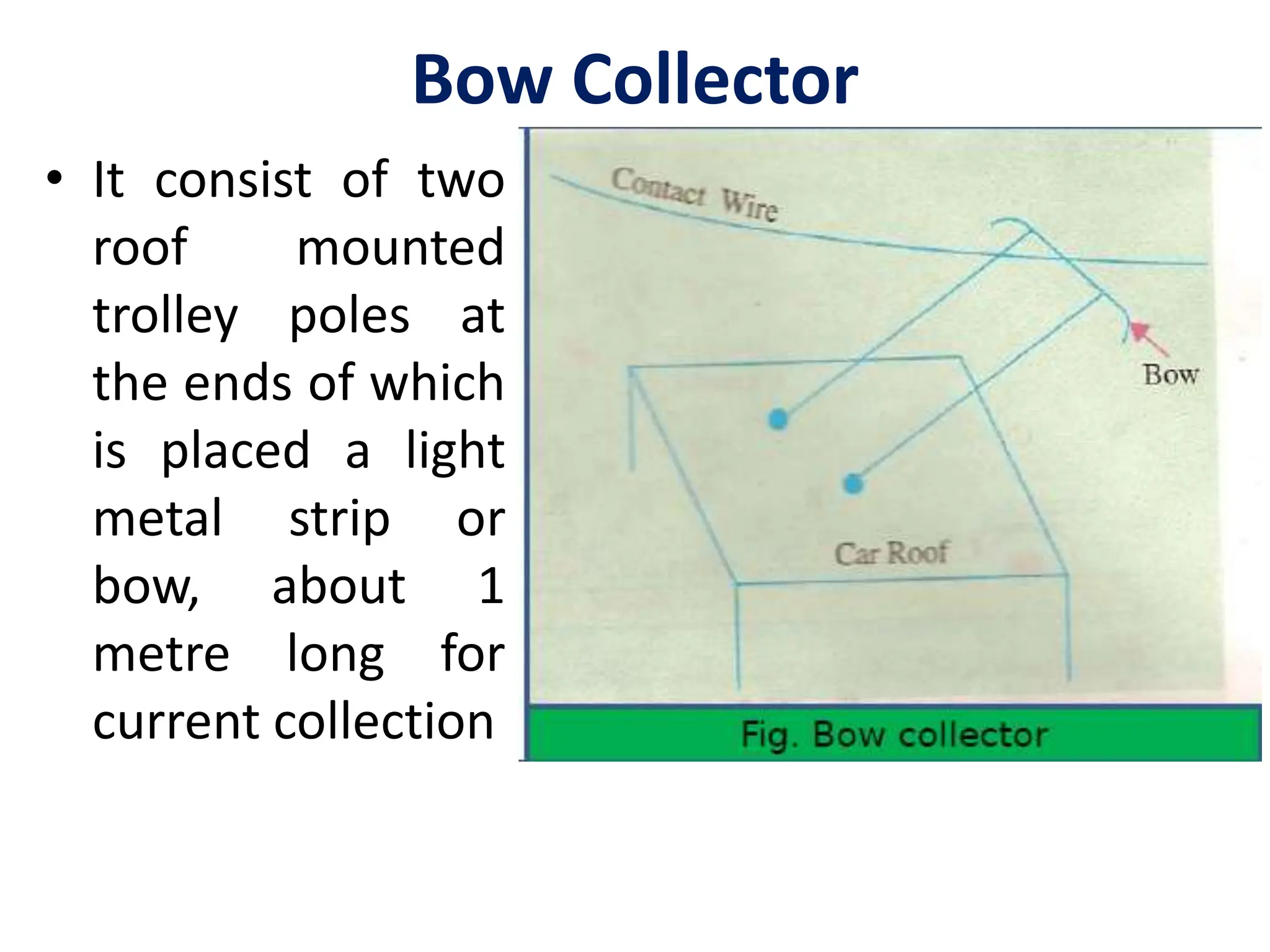
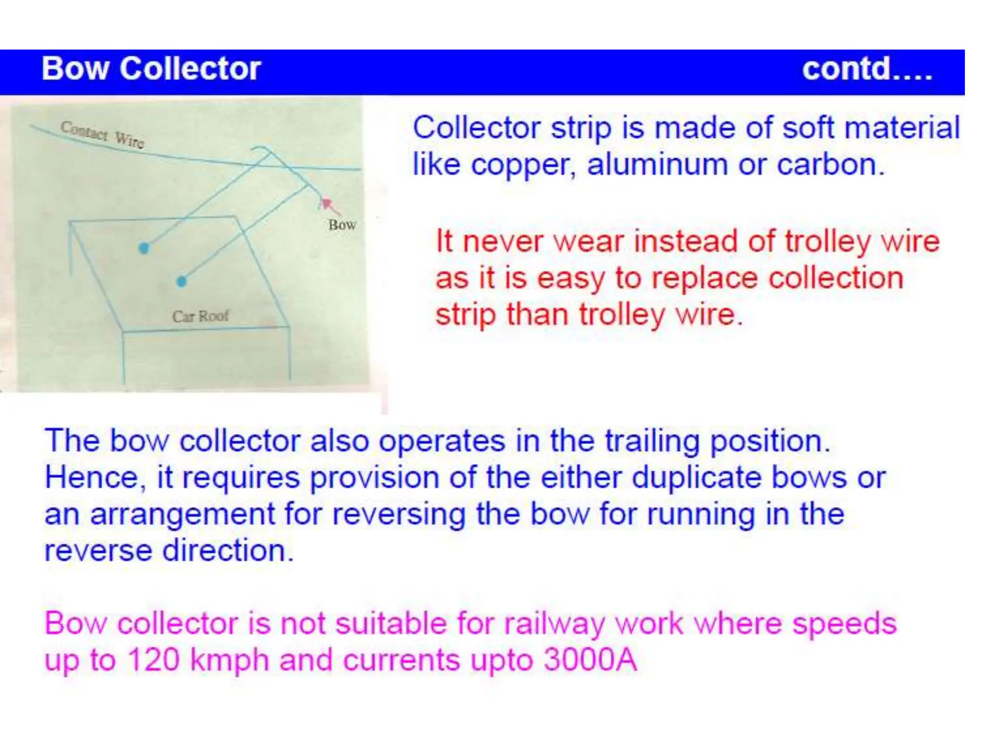
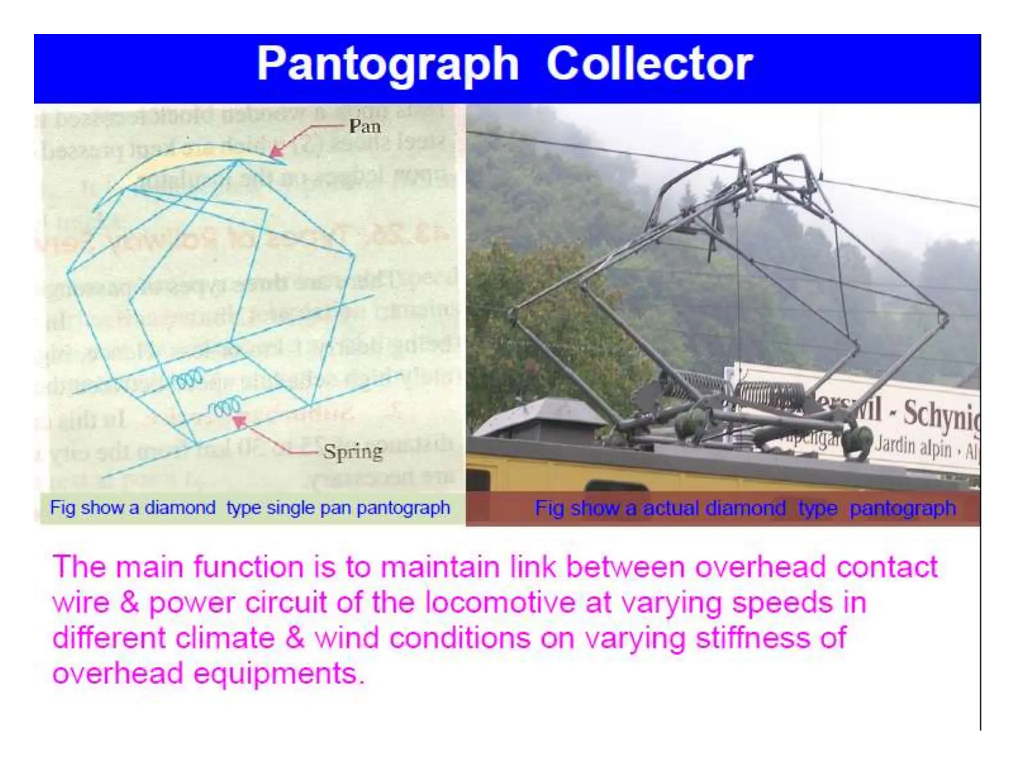
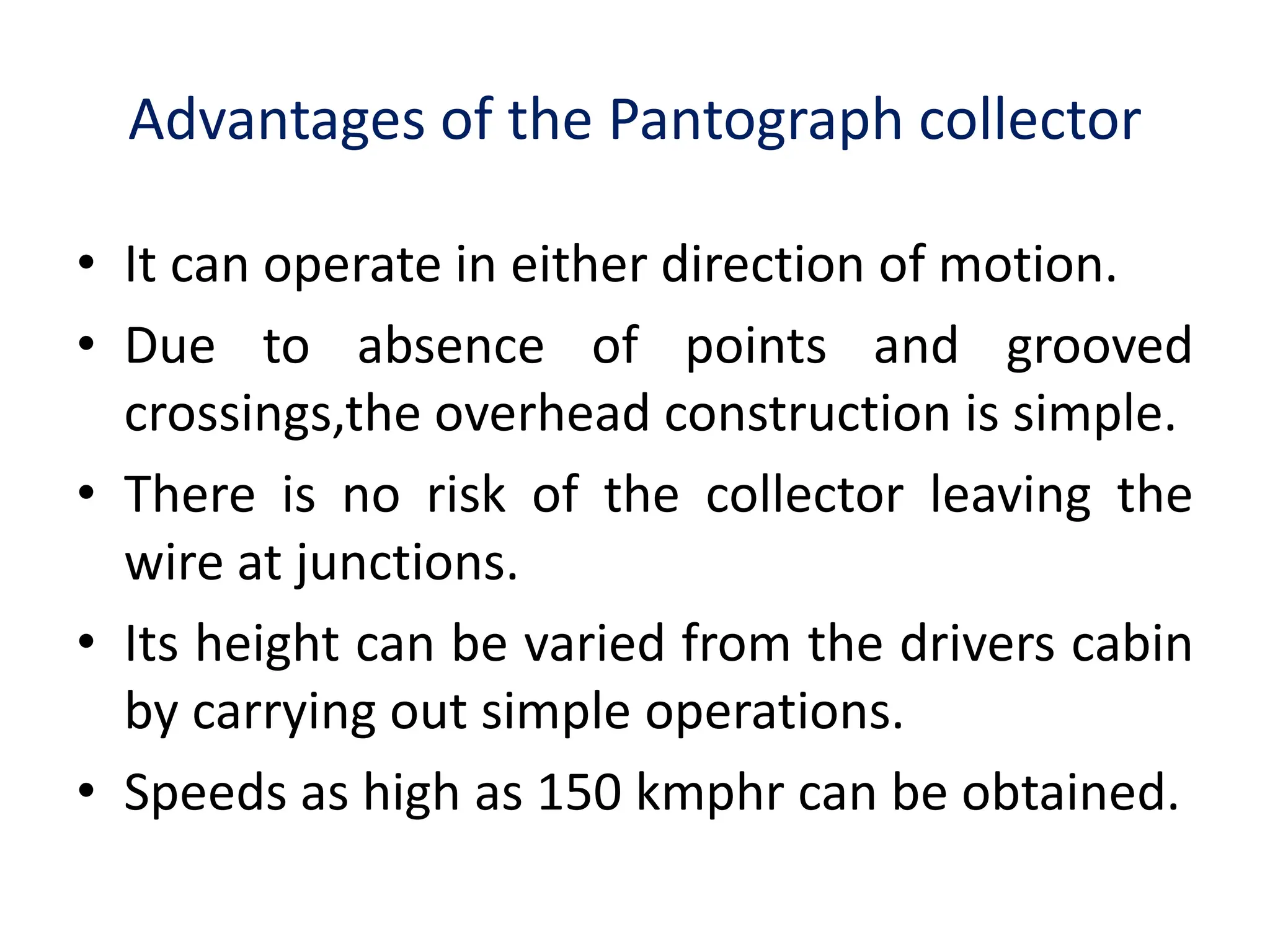
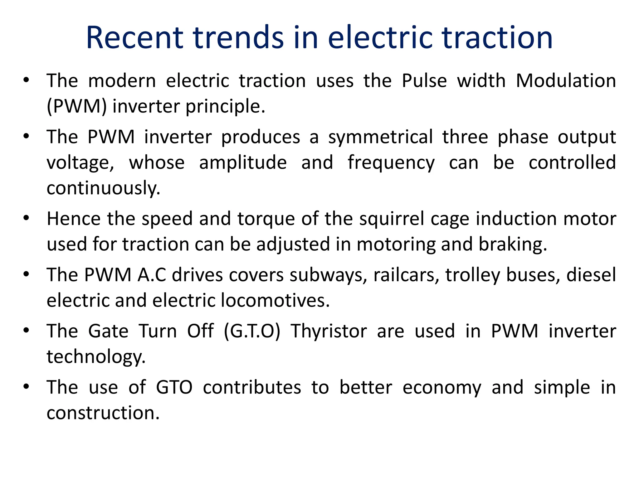
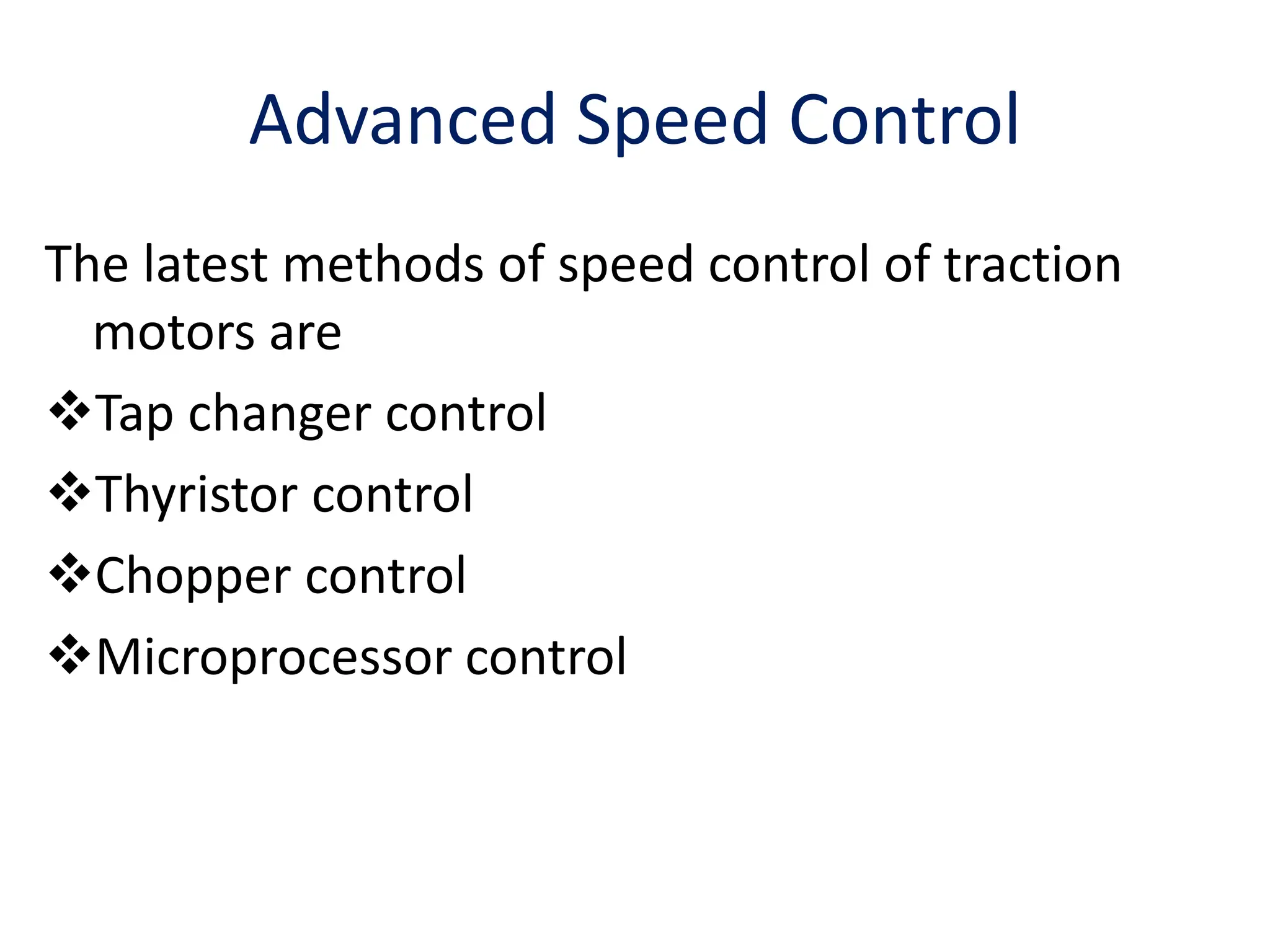
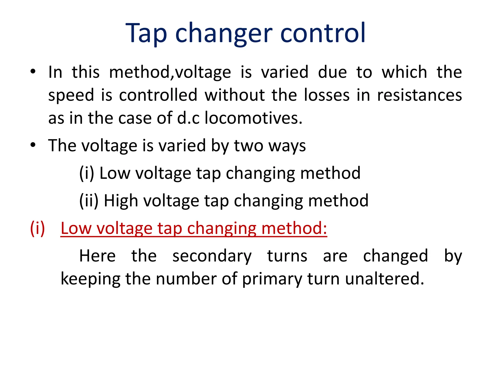
Current Collection System
 There are mainly two systems of current
collection for locomotives,tramways or trolley
buses namely,
1. Conductor rail system.
2. Overhead System.
Conductor rail system
• It is employed at 600 V for suburban services as it is
relatively cheaper,the inspecttion and maintenance
are easier.
• In this system,current is supplied to the electically
operated vehicle either through one rail conductor or
through two rail conductor.
• In case of one rail conductor the track rail is used as
the return conductor.
• The rails are mounted on insulators parallel with the
track rails at a distance of 0.3 to 0.4 m from the
running rail.
Conductor rail system....
• The wear on the conductor rail is only due to the
friction of the collector shoes and pitting occurs at
starting when the current drawn is very large.
• The main considerations with which the rails are
designed are,
(1) Electrical conductivity,
(2) Cost
(3) Wearing qualities
(4) contact surface available for the collector shoes
(5) shape and size of the conductor rail.
Conductor rail system....
• A special steel alloy is used for the rails for economy
reasons.
• A typical composition is Iron- 99.63%,Carbon- 0.05%,
Manganese- 0.2%,Phosphorus- 0.05%,Silicon-0.02%
and Sulphur-0.05%.
• The conductor rail is not fixed rigidly to the insulators
in order to take care of the contraction and expansion
of rails.
• The current is conveyed from the conductor rail to the
train equipment by means of collector shoe which
presses onto the rail with a force of about 15 Kg.
Conductor rail system....
• In case of top contact the necessary contact force is
obtained by gravity.
• In case of side and under running contacts springs
are employed to obtain necessary contact force.
• The current can be collected at about 300 to 500 A.
• At least two shoes must be provided on each side to
avoid discontinuity in the current flow.
• This system is suitable for heavy current
collection,for voltages up to 1200 V.
Overhead System
• This system is adopted when the trains are to be
supplied at high voltage say 1500 V or above.
• The high power for trains may be supplied through
conductors of relatively small cross section and
collection of current required by a train can be done by
a collector with sliding contact.
• This system is usedfor all a.c railways and is also used
with d.c tramways,trolley buses and locomotives
operating at voltages of 1500 V and above.
• In all these cases the running rails are utilized as the
return conductor therefore, with d.c and single phase
system only one overhead wire is required for each
track.
Trolley Wires or Contact wire
• The trolley wire or contact wire must be suspended
with the minimum of sag
• so that it remains practically horizontal.
• So that the contact between the wire & current
collector may be maintained at high speeds.
• This is achieved by which the trolley wire(contact
wire) is supported by another wire known a the
“catenary” or “Messenger”
• The catenary construction are different types
• 1. Single catenary construction.
• 2. compund catenary construction
Trolley wire
Single catenary construction …
• The distance of droppers is between 3 to 5 metres
curved track the spans of shorter length are employed.
• Such construction provides for speed upto 30 to 50
kmph
Advantages
• It is relatively cheaper.
• Less maintenance.
• Single catenary construction is considered suitable for
most light Weight a.c. system.
• Suitable for secondary routes where traffic is light.
Compound catenary construction
Employed for heavy current i.e where traffic density is high.
It consist of three wires.
1.The upper wire is catenary wire, which is insulated from the
supporting structure
2. The another wire known as intermediate catenary, is
supported by droppers clipped to both wires.
3. Third wire i.e trolley wire.
Compound catenary …
• Trolley wire is suspended from intermediate catenary by solid
wire loop droppers which are to slide vertically on the
intermediate wire & fixed the trolley wire.
• The purpose of intermediate catenary, besides increasing the
current carrying capacity, is to provide for more uniformity in
Elasticity.
• The compound catenary is used on lines where speed ranges is
190 to 224 kmph.
Current Collector
Current Collectors for Overhead System
• The current in the overhead system is collected with the
help of sliding contact collector mounted on the roof of
the vehicle.
• The primary requirement of a collector is that it should
maintain a continuous contact with trolley wire at all
speeds.
• Three types of commonly used current collectors are,
(1) Trolley Collector
(2) Bow Collector
(3) Pantograph collector
Trolley Collector
• This collector is used for
Tramways & trolley buses
& is mounted on the roof
of the vehicle contact
with overhead wire.
• It is made either grooved
wheel or a sliding shoe
carried at the end of a
light trolley pole attached
to the top of the vehicle
& held in contact with
overhead wire by means
of a spring.
Bow Collector
• It consist of two
roof mounted
trolley poles at
the ends of which
is placed a light
metal strip or
bow, about 1
metre long for
current collection
Pantograph collector...
• A positive pressure has to be maintained at all Times to
avoid loss of contact & sparking.
• But pressure must be as low as possible so that wear of
overhead contact wire is minimum.
• It consists of a pantograph framework (of high tensile
alloy-steel tubing) which can be raised or lowered from
cabin by compressed air or springs.
• It is used where the vehicles run at high speeds;i.e.,in
railways and where currents to be collected are large
(2000A to 3000A).
Advantages of the Pantograph collector
• It can operate in either direction of motion.
• Due to absence of points and grooved
crossings,the overhead construction is simple.
• There is no risk of the collector leaving the
wire at junctions.
• Its height can be varied from the drivers cabin
by carrying out simple operations.
• Speeds as high as 150 kmphr can be obtained.
Recent trends in electric traction
• The modern electric traction uses the Pulse width Modulation
(PWM) inverter principle.
• The PWM inverter produces a symmetrical three phase output
voltage, whose amplitude and frequency can be controlled
continuously.
• Hence the speed and torque of the squirrel cage induction motor
used for traction can be adjusted in motoring and braking.
• The PWM A.C drives covers subways, railcars, trolley buses, diesel
electric and electric locomotives.
• The Gate Turn Off (G.T.O) Thyristor are used in PWM inverter
technology.
• The use of GTO contributes to better economy and simple in
construction.
Advanced Speed Control
The latest methods of speed control of traction
motors are
Tap changer control
Thyristor control
Chopper control
Microprocessor control
Tap changer control
• In this method,voltage is varied due to which the
speed is controlled without the losses in resistances
as in the case of d.c locomotives.
• The voltage is varied by two ways
(i) Low voltage tap changing method
(ii) High voltage tap changing method
(i) Low voltage tap changing method:
Here the secondary turns are changed by
keeping the number of primary turn unaltered.
(ii) High voltage tap changing method:
• Here the turn ratio of the transformer kept
constant and variable voltage is applied on the
primary.
• The variable voltage is obtained from other
tap changing auto transformers.
• When tap changer is provided on HT or LT side
of the transformer,it is necessary to maintain a
continuous tractive effort without interrupting
the current of the traction motors.
Thyristor control
• When d.c traction motors are fed with rectified a.c
supply,magnitude of d.c voltage is decided by the
average of the positive half cycles allowed to pass
through the rectifiers.
• This can be controlled in two ways,
(a) Only portion of the +ve half cycle is allowed to pass
through the rectifier decided by the instant in +ve
half cycle when +ve gate pulse is applied.
(b) A certain number of +ve half cycles are not allowed
to be rectified by missing +ve gate pulses for those
cycles.
Chopper control
• Control of d.c motors supplied from d.c supply is
achieved by means of a thyristor switching circuit
called the chopper.
• In chopper circuits,the voltage is varied by changing
the ON-OFF time duration ratio for which the d.c
supply voltage is applied to the motor.
• This provides an efficient and step less control of d.c
motors.
• Field choppers are also used for varying the fields
and thereby the speed and torque are controlled.
Microprocessor control
• The microprocessor can be used to control the speed of
a d.c motor.
• A speed to digital converter having high resolution,high
accuracy and small detecting time is used for making
digital speed measurements.
• A current detector, speed detector,
continuous/discontinuous current detector and the
gate pulse circuit with associated pulse amplifiers for
the SCR converter’s line, synchronizing circuit are
included as a peripheral circuit.
• The speed measurements and proportional and integral
compensation operations are made during the speed
control process.
Microprocessor control....
• The line synchronizing circuit is included so
that the microprocessor can synchronise the
firing pulse generation data with the supply
frequency.
• The gate pulse generator is the separate firing
circuit receiving control signal from the
microprocessor.
• The firing circuit can also have a
microprocessor based control with a
regeneration braking facility.
Advantages of microprocessor based drives are,
High speed of response
High accuracy
Over voltage and over speed protection
Electronic interlocking
Less sensitive to temperature variations and
drift.
Number of components used are less.

Electric Traction Current Collection System.ppt

  • 1.
    Current Collection System There are mainly two systems of current collection for locomotives,tramways or trolley buses namely, 1. Conductor rail system. 2. Overhead System.
  • 2.
    Conductor rail system •It is employed at 600 V for suburban services as it is relatively cheaper,the inspecttion and maintenance are easier. • In this system,current is supplied to the electically operated vehicle either through one rail conductor or through two rail conductor. • In case of one rail conductor the track rail is used as the return conductor. • The rails are mounted on insulators parallel with the track rails at a distance of 0.3 to 0.4 m from the running rail.
  • 4.
    Conductor rail system.... •The wear on the conductor rail is only due to the friction of the collector shoes and pitting occurs at starting when the current drawn is very large. • The main considerations with which the rails are designed are, (1) Electrical conductivity, (2) Cost (3) Wearing qualities (4) contact surface available for the collector shoes (5) shape and size of the conductor rail.
  • 5.
    Conductor rail system.... •A special steel alloy is used for the rails for economy reasons. • A typical composition is Iron- 99.63%,Carbon- 0.05%, Manganese- 0.2%,Phosphorus- 0.05%,Silicon-0.02% and Sulphur-0.05%. • The conductor rail is not fixed rigidly to the insulators in order to take care of the contraction and expansion of rails. • The current is conveyed from the conductor rail to the train equipment by means of collector shoe which presses onto the rail with a force of about 15 Kg.
  • 6.
    Conductor rail system.... •In case of top contact the necessary contact force is obtained by gravity. • In case of side and under running contacts springs are employed to obtain necessary contact force. • The current can be collected at about 300 to 500 A. • At least two shoes must be provided on each side to avoid discontinuity in the current flow. • This system is suitable for heavy current collection,for voltages up to 1200 V.
  • 7.
    Overhead System • Thissystem is adopted when the trains are to be supplied at high voltage say 1500 V or above. • The high power for trains may be supplied through conductors of relatively small cross section and collection of current required by a train can be done by a collector with sliding contact. • This system is usedfor all a.c railways and is also used with d.c tramways,trolley buses and locomotives operating at voltages of 1500 V and above. • In all these cases the running rails are utilized as the return conductor therefore, with d.c and single phase system only one overhead wire is required for each track.
  • 8.
    Trolley Wires orContact wire
  • 10.
    • The trolleywire or contact wire must be suspended with the minimum of sag • so that it remains practically horizontal. • So that the contact between the wire & current collector may be maintained at high speeds. • This is achieved by which the trolley wire(contact wire) is supported by another wire known a the “catenary” or “Messenger” • The catenary construction are different types • 1. Single catenary construction. • 2. compund catenary construction Trolley wire
  • 13.
    Single catenary construction… • The distance of droppers is between 3 to 5 metres curved track the spans of shorter length are employed. • Such construction provides for speed upto 30 to 50 kmph Advantages • It is relatively cheaper. • Less maintenance. • Single catenary construction is considered suitable for most light Weight a.c. system. • Suitable for secondary routes where traffic is light.
  • 14.
    Compound catenary construction Employedfor heavy current i.e where traffic density is high. It consist of three wires. 1.The upper wire is catenary wire, which is insulated from the supporting structure 2. The another wire known as intermediate catenary, is supported by droppers clipped to both wires. 3. Third wire i.e trolley wire.
  • 15.
    Compound catenary … •Trolley wire is suspended from intermediate catenary by solid wire loop droppers which are to slide vertically on the intermediate wire & fixed the trolley wire. • The purpose of intermediate catenary, besides increasing the current carrying capacity, is to provide for more uniformity in Elasticity. • The compound catenary is used on lines where speed ranges is 190 to 224 kmph.
  • 16.
  • 17.
    Current Collectors forOverhead System • The current in the overhead system is collected with the help of sliding contact collector mounted on the roof of the vehicle. • The primary requirement of a collector is that it should maintain a continuous contact with trolley wire at all speeds. • Three types of commonly used current collectors are, (1) Trolley Collector (2) Bow Collector (3) Pantograph collector
  • 18.
    Trolley Collector • Thiscollector is used for Tramways & trolley buses & is mounted on the roof of the vehicle contact with overhead wire. • It is made either grooved wheel or a sliding shoe carried at the end of a light trolley pole attached to the top of the vehicle & held in contact with overhead wire by means of a spring.
  • 20.
    Bow Collector • Itconsist of two roof mounted trolley poles at the ends of which is placed a light metal strip or bow, about 1 metre long for current collection
  • 23.
    Pantograph collector... • Apositive pressure has to be maintained at all Times to avoid loss of contact & sparking. • But pressure must be as low as possible so that wear of overhead contact wire is minimum. • It consists of a pantograph framework (of high tensile alloy-steel tubing) which can be raised or lowered from cabin by compressed air or springs. • It is used where the vehicles run at high speeds;i.e.,in railways and where currents to be collected are large (2000A to 3000A).
  • 24.
    Advantages of thePantograph collector • It can operate in either direction of motion. • Due to absence of points and grooved crossings,the overhead construction is simple. • There is no risk of the collector leaving the wire at junctions. • Its height can be varied from the drivers cabin by carrying out simple operations. • Speeds as high as 150 kmphr can be obtained.
  • 25.
    Recent trends inelectric traction • The modern electric traction uses the Pulse width Modulation (PWM) inverter principle. • The PWM inverter produces a symmetrical three phase output voltage, whose amplitude and frequency can be controlled continuously. • Hence the speed and torque of the squirrel cage induction motor used for traction can be adjusted in motoring and braking. • The PWM A.C drives covers subways, railcars, trolley buses, diesel electric and electric locomotives. • The Gate Turn Off (G.T.O) Thyristor are used in PWM inverter technology. • The use of GTO contributes to better economy and simple in construction.
  • 26.
    Advanced Speed Control Thelatest methods of speed control of traction motors are Tap changer control Thyristor control Chopper control Microprocessor control
  • 27.
    Tap changer control •In this method,voltage is varied due to which the speed is controlled without the losses in resistances as in the case of d.c locomotives. • The voltage is varied by two ways (i) Low voltage tap changing method (ii) High voltage tap changing method (i) Low voltage tap changing method: Here the secondary turns are changed by keeping the number of primary turn unaltered.
  • 28.
    (ii) High voltagetap changing method: • Here the turn ratio of the transformer kept constant and variable voltage is applied on the primary. • The variable voltage is obtained from other tap changing auto transformers. • When tap changer is provided on HT or LT side of the transformer,it is necessary to maintain a continuous tractive effort without interrupting the current of the traction motors.
  • 29.
    Thyristor control • Whend.c traction motors are fed with rectified a.c supply,magnitude of d.c voltage is decided by the average of the positive half cycles allowed to pass through the rectifiers. • This can be controlled in two ways, (a) Only portion of the +ve half cycle is allowed to pass through the rectifier decided by the instant in +ve half cycle when +ve gate pulse is applied. (b) A certain number of +ve half cycles are not allowed to be rectified by missing +ve gate pulses for those cycles.
  • 30.
    Chopper control • Controlof d.c motors supplied from d.c supply is achieved by means of a thyristor switching circuit called the chopper. • In chopper circuits,the voltage is varied by changing the ON-OFF time duration ratio for which the d.c supply voltage is applied to the motor. • This provides an efficient and step less control of d.c motors. • Field choppers are also used for varying the fields and thereby the speed and torque are controlled.
  • 31.
    Microprocessor control • Themicroprocessor can be used to control the speed of a d.c motor. • A speed to digital converter having high resolution,high accuracy and small detecting time is used for making digital speed measurements. • A current detector, speed detector, continuous/discontinuous current detector and the gate pulse circuit with associated pulse amplifiers for the SCR converter’s line, synchronizing circuit are included as a peripheral circuit. • The speed measurements and proportional and integral compensation operations are made during the speed control process.
  • 32.
    Microprocessor control.... • Theline synchronizing circuit is included so that the microprocessor can synchronise the firing pulse generation data with the supply frequency. • The gate pulse generator is the separate firing circuit receiving control signal from the microprocessor. • The firing circuit can also have a microprocessor based control with a regeneration braking facility.
  • 34.
    Advantages of microprocessorbased drives are, High speed of response High accuracy Over voltage and over speed protection Electronic interlocking Less sensitive to temperature variations and drift. Number of components used are less.