

Recommended
Recommended
More Related Content
What's hot
What's hot (8)
Similar to Electrical Boundary Conditions Explained
Similar to Electrical Boundary Conditions Explained (20)
More from cairo university
More from cairo university (20)
Recently uploaded
Recently uploaded (20)
Electrical Boundary Conditions Explained
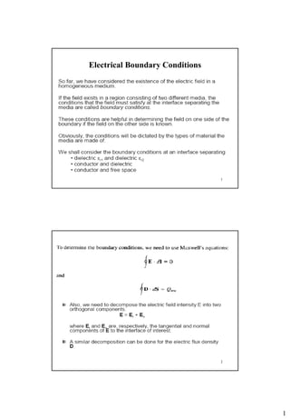
- 2. 2 3 an2 is a unit vector normal to the interface from region 2 to region1 4 Electric Field Boundary Conditions:
- 3. 3 5 Magnetic Field Boundary Conditions: 6 K=Js K=Js
- 4. 4 7 Dielectric- dielectric boundary conditions Dielectric materials are dominated by “bound” rather than “free’’ charges (E-fields causes +ve and –ve charges of molecules to separate and form dipoles throughout the material interior Therefore, the free charge density sand the surface current density Js are zero 1En1= 2En2 •The normal component of B is continuous across the interface while the tangential component of E is continuous across the interface 2 2 1 1 tt BB 8 Conductor-dielectric boundary conditions snDn 1
- 5. 5 9 Conductor-free space boundary conditions 01 1 0 t t ED snn ED 101 10
- 6. 6 11 12
- 7. 7 13 (Not Yet) 14 Electrodynamics • Electrostatic charges electrostatic fields • Steady currents (motion of electric charges with uniform velocity magnetostatic fields • Time varying currents electromagnetic fields
- 8. 8 15 Changing Magnetic Field Current and Voltage Current N S B, H 16 Faraday’s Law VLOOP = -E.dl Fmagnetic = total magnetic “flux” = B.ds Faraday’s Law : Rate of change of magnetic flux through a loop = emf (voltage) around the loop . .mag loop surface d d dt dt F B Edl ds B, H N S
- 9. 9 17 Lenz’s Law B, H Lenz’s Law emf appears and current flows that creates a magnetic field that opposes the change – in this case an increase – hence the negative sign in Faraday’s Law. B, H N S V-, V+ Iinduced 18 Lenz’s Law B, H Lenz’s Law emf appears and current flows that creates a magnetic field that opposes the change – in this case an decrease – hence the negative sign in Faraday’s Law. B, H N S V+, V- Iinduced
- 10. 10 Relative motion between magnet and the coil galvanometer shows deflection Relative motion faster more deflection No of turns of the coil increased greater deflection 19 20 In summary: Faraday’s Law- Integral Form
- 11. 11 21 Faraday’s Law-Differential Form -There are different methods to generate an Electric Field HW: How? (Use illustrations) - According to Faraday’s Law: how can you change the magnetic flux density? (Use illustrations) 22
- 12. 12 23 TMS: 24
- 13. 13 Faraday’s Law in increasing osteogenesis 25 HW • https://www.youtube.com/watch?v=V7vOgHqE_P4 • http://www.youtube.com/watch?v=XJtNPqCj-iA • From Basic Introduction to Bioelectromagnetics book: Read: - Inductive telemetry for communication with medical implants. -The difficulty in propagating through skin-fat- muscle-layers (you could find a question related to these topics in the exam). 26
- 14. 14 Telemetry • It is often useful to monitor body parameters such as temperature, pressure, oxygen content of blood, heart rate, etc. The transducers that measure these parameters must often be inside the human body. This poses two main problems: how to get the information of the measured parameter out of the body and how to power the circuit. 27 Wires through the skin? • Not a good idea: • Nasty wound • Mechanical stress could pull the wire out • Danger of electrocution • Discomfort Internal batteries? • Need surgery to replace battery • Dangerous chemicals could leak • Telemetry without internal batteries can use inductive coupling. 28
- 15. 15 29 The voltage induced in the second winding is given by V 2= −N2 dφ/dt If the flux varies as φ = φ0 sinωt then the induced voltage is V2 = N2 ωφ0 cosωt Increasing the number of turns increases the induced voltage - but also the size of the coil! Ferromagnetization of Target Tissues by Interstitial Injection of Ferrofluid • Magnetic Retraction versus graspers. • Ferromagnetic particles injected into submucosal layer of Porcine stomach. • Simple magnetic probe for tissue retraction and resection 30
- 16. 16 Spatial distribution of the electric field at the bottom of a petri dish placed at the center between two helmholtz coils (B field is perpendicular to the dish) –used to expose cells to low frequency EMFs Arrow plot (direction)of the electric field at the bottom of a petri dish placed at the center between two helmholtz coils (B field is perpendicular to the dish)
- 17. 17 33 Time Harmonic fields and their phasor representation 34 • In general, a phasor could be a scalar or vector. • If a vector E (x, y, z, t) is a time-harmonic field, the phasor form of E is Es (x, y, z); the two quantities are related as E = Re (Es e jt) If E = Eocos(t -x)ay, we can write E as: E = Re (Eoe -j x ay e jt ) Es = Eo e -j x ay phasor form Notice that j E tE Ej t E eEjeE tt E tj s tj s )Re()Re(
- 18. 18 35 • Maxwell’s equations in terms of vector field phasors (E, H) and source phasors (, J) in a simple linear, isotropic and homogeneous medium are: 00 dSHH dvdSEE dSEjdSJdlHEjJH dSHjdlEHjE S ss v vs S s vs s L s s ssssss L s ssss From the table, note that the time factor e jt disappears because it is associated with every term and therefore factors out, resulting in time independent equations 36
- 19. 19 37 Plane Wave Equations 38 Electromagnetic wave equation in free space (coupling between E and H)
- 20. 20 39 40 Waves in General • A wave is a function in both space and time. • The variation of E with both time and space variable z, we may plot E as a function of t by keeping z constant and vice versa.
- 21. 21 41 The possible solution in free space is of the form: )cos()cos( ]Re[ )Re(),( )()( ztEztE eEeE eEtzE omom ztj m ztj m tj xx oo A negative sign in (t oz) is associated with a wave propagating in the +z direction (forward traveling or positive going wave) whereas a positive sign indicates that a wave is traveling in the –z direction (backward traveling or negative going wave) 42
- 22. 22 43 A plane wave traveling in the positive z direction )cos( ]Re[ ])(Re[),( 0 )(0 ztEor eEor ezEtzE ox ztj x tj xx o 44 What do Faraday and Ampere mean? . . t dlE s B d . .C t sH D dl J d “a changing magnetic field causes an electric field” “a changing electric field/flux causes an magnetic field” Question : If we put these together, can we get electric and magnetic fields that, once created, sustain one another?
- 23. 23 45 Cross-breed Ampere and Faraday! C t t t t ... all in terms of E and H ... all in terms of D E E H J a B H E E nd H dt d t d t d t ... differentiate both sides ... curl of both E H E H E sides 2 2 d d d d dt dt d t d t H E H E E 2 2 d dt d dt E E E 46 Cross-breed Ampere and Faraday! C t t t t ... all in terms of E and H ... all in terms of D E E H J a B H E E nd H t t t ... curl of b H E oth sid s E E E e E H 2 2 t t H H H
- 24. 24 47 Now some simplifications … E = (0,EY,0) only x y z EY = EY0sin(ωt-βx) Align y-axis with electric field and the x-axis with the direction of (wave) propagation (a travelling wave propagating in the x- direction, with only a y-component of E-field) 48 Plane Wave We will also look for a plane wave solution – where the field EY is the same (at an instant in time) across the entire zy plane. Here is an animation to see what this means - looking at the yz plane, down the direction of travel Look down here E = (0,EY,0) only x y z EY = EY0sin(ωt-βx)
- 25. 25 49 Cross-breed Ampere and Faraday! ,0 , 0 0 y y y dE dEd d d dx dy dz dz dx E i j k E 2 2 2 2 2 2 , , 0 y y y y y y d E d E d E d Ed d d dx dy dz dxdy dzdydz dx dE dE dz dx i j k E And, as we have simplified down to E=(0,Ey,0), with |EY| constant in the zy plane, this reduces to … 2 2 y y d E dx E 50 Cross-breed Ampere and Faraday! • Plane wave equation for E – describes the variation in time and space of an electric plane wave • With a y-component only (we have aligned the y-axis with E) • propagating in the x-direction. • There is an exactly equivalent equation for H – Eliminate E, not H, from the combination of Ampere and Faraday. • rather a waste of our time. • We can, however, infer that whatever behaviour we get for Ey will apply to H, although we do not yet know the direction of H. 2 2 2 2 y y yd E dE d E dtdx dt Becomes the 1D equation 2 2 d d dt dt E E ESo (in 3D)
- 26. 26 51 What have we here? 2 2 2 2 y y yd E dE d E dtdx dt Variation of Ey in space (x=direction of propagation) Variation of Ey with time Magnetic permeability (4px107 in vacuum, larger in a magnet) Conductivity (0 in an insulator, much larger in a conductor) Dielectric constant (8.85x10⁻¹² in a vacuum, larger in a dielectric) 52 Start with an insulator to make life easy (=0) 2 2 2 2 y yd E d E dx dt ( ) 0 j t x y yE E e Look for a solution of the form Where and depend upon and … the characteristics of the insulator 2 2 2 2 y y yd E dE d E dtdx dt becomes 2 2 2 2 2 2 2 2 1 ,y y y y d E d E E E dx dt 2 2 1 , what does this mean?? ,2 2 2 2 Remember, = = waveleng f t requency d h an= f v f p p p p
- 27. 27 53 Still don’t know what it means … • Travelling wave of the form ( ) 0 0 cosj t x y y yE E e E t x 2 12 It travels with a velocity fv p p In a vacuum, =0=4px10-7, =0=8.85x10⁻¹² 8 0 0 1 3 10 / ... a familiar speed?v m s In (eg) glass, =0=4px10-7, =r0=5x8.85x10-12 8 0 0 1 1.43 10 / ... light slows down in glass r v m s 54 This is why lenses work … V=3x10⁸m/s V=1.43x10⁸m/s V=3x10⁸m/s
- 28. 28 55 What is H up to? ( ) (0, ,0)j t x yE e E ( ) 00,0 , 0,0, , j t x y ydE d j x E t e H Faraday says E E 0 0(0,0, ) , 0,0, H H j t jx z z z t x zH H H e t j H e So and if ( ) 0 0 j t x j t x z yH e E e H E time-phaand are in in a non-conduse ctor 0 0 0 0 1 1 Also, z y y yH E E E (0,0, ) (0, ,0)So and are at 90 to one another ... andz yH EH E iZ , the intrinsic impedance ( )of t realhe medium, is for an insulator 56 Summary so far : Insulator • H and E both obey ej(t-x) • H and E are in time-phase • |E|=Zi|H| is the characteristic impedance – Zi is real in an insulator – Zi = 377Ω in free space (air!) – Zi ≈ 150Ω in glass • Wave travels at a velocity v =1/√ – 3x10⁸ m/s in free space
- 29. 29 57 Now a conductor … • Fields lead to currents • Currents cause “Joule heating” (I2R) • Leads to loss of energy • Fields still oscillate, but they decay • Multiply the solution we have already by a term e-ax? e-ax e-ax sin(ωt-βx) HEAT ! HEAT! HEAT! 58 Now a conductor … • In general: the electric field in a conductor may be expressed in the form: )cos()cos( ))(Re(),( aa xteExteE exEtxE x m x m tj yy Where mm EandE were replaced in terms of their mag. and phases
- 30. 30 59 Now a conductor … >0 ( > ) 2 2 2 2 y y yd E dE d E dtdx dt ( ) 0 j t x y y x E E e e a Look for a solution of the form 0 j xj t y yE E e e a 2 2 2 0 0 0 0y y y yj E E j E Ea .j a For tidiness, write is called the propagation constant 2 ,j j j j 0 x j t y yE E e e 60 Example : Good Conductor f a v 6x10⁷ (S/m) 100MHz 6.28x10⁸ 8.85x10⁻¹² 1.26x10⁻⁶ 1.54x10⁵ 1.54x10⁵ 4x10³m/s 0 ,x j t y yE E e e j j 3 3 5 790 6 10 0.006 790 6 10 1.54 10 (1 )j x j x j x j Comments : a= , so E and H are 45° out of (time) phase v<< speed of light a = 1.54x10⁵ >>1 … rapid attenuation via e-ax Let’s have a look at e-ax …
- 31. 31 61 Example : Good Conductor e-ax 0 0.1 0.2 0.3 0.4 0.5 0.6 0.7 0.8 0μm 10μm 20μm 30μm 0.36=1/e Amplitude falls by 0.36=1/e in 6m i.e. the wave doesn’t get far in copper! Skin Depth : the depth of penetration into a good conductor (the wave will be attenuated by a factor pa f e 11 368.01 62 Example : Good Conductor, E=ZiH …. Intrinsic Impedance 0 0(0,0, ) , 0,0, So and if j t j t x z x z z z j H eH H H e t H H 00,0 , 0 ,, ,0 H Faraday says E E y j t x y d e E E dxt 0 0 0y z i z i j E H Z H j j j Z jj j
- 32. 32 63 Example : Good Conductor, E=Zi H…. Intrinsic Impedance 4 0 0 0 0 0 j y i z z z z j j E Z H H H e H j p 0 0 4 H E y z j E H e p So relates the magnitudes of and 0 0 4 y zE H p and leads by Recall Plane wave propagation: Reduction of plane wave amplitude in tissue (propagation along z) 22 22 0for0 EkE (Derive?)/11 2 2 mNpo a 377,0 )0medium(lossy1 )00,(1 a a Air conductor mediumlosslessinsulator mrado /11 2 2
- 33. 33 HW • For a frequency of 433 MHz, the muscle has r= 64.21, = 0.9695 S/m • If we use 2/3 muscle to represent the human body, then * r , by 2/3 to give r = 42.81 and σ = 0.6463 S/m. • Calculate α, β, λ = 2p/ β, velocity of propagation vp • If the electric field just inside the body Eo= 1 V/m, the field at z = 10 cm inside the 2/3 muscle material will be E0 e–αz =?. The power will be reduced by e–2αz to ? % of its original value. 65 Electromagnetic waves and the human body 66
- 34. 34 Can you generate both figures (calculate a, and substitute in E = Eo exp(- a z) 67 68 Similarities and differences between the propagation of uniform plane waves in free space and conductive medium Similarities: • In both cases, the electric and magnetic fields are uniform in the plane perpendicular to the direction of propagation. • The electric and magnetic fields are perpendicular to each other, and to the direction of propagation i.e.no component of either the electric or the magnetic field is in the direction of propagation.
- 35. 35 69 Differences: Free Space Conductive Medium • E, H vectors are in phase, the E, H vectors are not in phase, the intrinsic wave impedance ois a real intrinsic wave impedance is a com- number. plex number. • The phase velocity = c (speed of The phase velocity is less than the light. speed of light. • For a plane wave of a given freq., o The =2p/ is shorter than o is longer than in the material medium. • Does not attenuate in magnitude as it It exponentially attenuates, with propagates. the skin depth by = 1/a 70 Polarization of plane waves • For a wave propagating along the z axis, the electric field may be expressed as having two components in the x and y direction: E = (A ax + B ay) e -jz where the amplitudes A and B may be complex. 1. If A and B have the same phase angle (a = b). In this case, the x and y components of the electric field will be in phase jbja eBBeAA , )cos()( )( )( aztaBaAE eaBaAE yx azj yx The tip of the E vector follows a line Linear polarization
- 36. 36 71 2. If A and B have different phase angles. In this case, E will no longer remain in one plane: The locus of the end point of the electric field vector will trace out an ellipse once each cycle Elliptical polarization 3. If A and B are equal in magnitude and differ in phase angle by p/2, the ellipse becomes a circle Circular Polarization )cos( )cos( zbtBE zatAE y x 72 - If one takes a snapshot of a circularly polarized wave at any instant then he will see the picture below. - The E-field vector does not change in magnitude but its direction “twists” in space. - An observer sitting in the path of the wave will see the E- field vector rotate in a circular trajectory at his location as the wave passes by.
- 37. 37 73 74
- 39. 39 77 Reflection at a Boundary (reflection of EM waves from body tissues) 78 ET HTHI EI HR ER
- 40. 40 79 )j-(1 120 ue)human tissas(suchsdielectriclossyFor , 2 coeffontransmissiH 2 tcoefficienreflection 2 1 r 12 1 I 12 1 12 12 12 12 211 p H E H E E HH HHH HHHEEE T I R IR TRI TRITRI HW • The electric field associated with a uniform plane wave propagating in air is given by • If this wave is normally incident on a glass medium of the following electrical properties (g = 5 o , µg = µo and g =0, determine the following 1. in air and in glass. 2. Reflection Γ and transmission Τ coefficients 3. Amplitudes of reflected and transmitted electric fields 80 mVztE xo i /a)10cos(1000 8 p
- 41. 41 81 HW: Report 1. Cell phones and health ( Tumors and cell phone use ). You need to support your claims by summarizing recent published scientific research. You also need to state what type of experiments/models were used to reach conclusions. 2. Exposure to electromagnetic radiation emitted by cell tower base stations. You need to include an answer to the question we asked at the beginning of the EM class. You also need to support your claims by summarizing recent publications. 3. Choose at least 3 medical (therapeutic or diagnostic) applications of EMFs and summarize the most recent publications related to the design, implementation, modeling and was it FDA approved (it does not have to be). You need to also show how did the inventors or users of the idea benefit from studying the material we covered in class so far. If you need ideas, contact me. (Hint: TMS, but do not use it in your report) 82