The piezoelectric inchworm motor uses a cyclical six-step process to achieve precise linear motion using three piezoelectric actuators. It functions by alternately extending and relaxing the lateral and clutching piezos to grip and move a shaft in small increments. Inchworm motors are commonly used for nanoscale positioning in scanning tunneling microscopes and patch clamping of biological cells due to their precise, smooth, and drift-free motion. New designs use lever mechanisms and roller guides to improve displacement and positioning accuracy for demanding precision applications.
8th International Conference on Soft Computing, Mathematics and Control (SMC ...
Inchworm motor.pptx
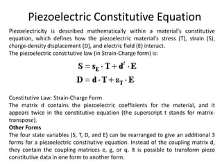
1. Piezoelectric Constitutive Equation
Piezoelectricity is described mathematically within a material's constitutive
equation, which defines how the piezoelectric material's stress (T), strain (S),
charge-density displacement (D), and electric field (E) interact.
The piezoelectric constitutive law (in Strain-Charge form) is:
Constitutive Law: Strain-Charge Form
The matrix d contains the piezoelectric coefficients for the material, and it
appears twice in the constitutive equation (the superscript t stands for matrix-
transpose).
Other Forms
The four state variables (S, T, D, and E) can be rearranged to give an additional 3
forms for a piezoelectric constitutive equation. Instead of the coupling matrix d,
they contain the coupling matrices e, g, or q. It is possible to transform piezo
constitutive data in one form to another form.
3. Hooke's Law and Dielectrics
• What is a constitutive equation? For mechanical problems, a constitutive
equation describes how a material strains when it is stressed, or vice-versa.
Constitutive equations exist also for electrical problems; they describe how
charge moves in a (dielectric) material when it is subjected to a voltage, or vice-
versa.
• Engineers are already familiar with the most common mechanical constitutive
equation that applies for everyday metals and plastics. This equation is known as
Hooke's Law and is written as:
• In words, this equation states: Strain = Compliance × Stress.
• However, since piezoelectric materials are concerned with electrical properties
too, we must also consider the constitutive equation for common dielectrics:
• In words, this equation states: ChargeDensity = Permittivity × ElectricField.
4. Coupled Equation
• Piezoelectric materials combine these two seemingly dissimilar constitutive
equations into one coupled equation, written as:
• The piezoelectric coupling terms are in the matrix d.
• In order to describe or model piezoelectric materials, one must have knowledge
about the material's mechanical properties (compliance or stiffness), its electrical
properties (permittivity), and its piezoelectric coupling properties.
Matrix Subscript Definitions
• The subscripts in piezoelectric constitutive equations have very important
meanings. They describe the conditions under which the material property data was
measured.
• For example, the subscript E on the compliance matrix sE means that the
compliance data was measured under at least a constant, and preferably a zero,
electric field.
• Likewise, the subscript T on the permittivity matrix eT means that the permittivity
data was measured under at least a constant, and preferably a zero, stress field.
10. Operation
• The actuation process of the inchworm motor is a six step
cyclical process after the initial relaxation and initialization
phase. Initially, all three piezos are relaxed and unextended. To
initialize the inchworm motor the clutching piezo closest to the
direction of desired motion (which then becomes the forward
clutch piezo) is electrified first then the six step cycle begins as
follows (see Figure):
• Step 1. Extension of the lateral piezo.
• Step 2. Extension of the aft clutch piezo.
• Step 3. Relaxation of the forward clutch piezo.
• Step 4. Relaxation of the lateral piezo.
• Step 5. Extension of the forward clutch piezo.
• Step 6. Relaxation of the aft clutch piezo.
11. • Electrification of the piezo actuators is accomplished by
applying a high bias voltage to the actuators in step according
to the "Six Step" process described above.
• To move long distances the sequence of six steps is repeated
many times in rapid succession. Once the motor has moved
sufficiently close to the desired final position, the motor may
be switched to an optional fine positioning mode.
• In this mode, the clutches receive constant voltage (one high
and the other low), and the lateral piezo voltage is then
adjusted to an intermediate value, under continuous feedback
control, to obtain the desired final position.
12. Applications
• The inchworm motor is commonly used in scanning tunneling
microscopes (STMs).
• An STM requires nanometer scale control of its scanning tip near
the material it is observing.
• This control can be accomplished by connecting the scanning tip
to the shaft of the inchworm motor.
• The inchworm motor, in turn, allows control in a direction normal
to the plane of the observed material's surface.
• Movement across the surface is commonly referred to as
movement in the x-y plane, whereas movement normal to the
surface is commonly referred to as movement in the z-direction.
• Movement of the scanning tip by the inchworm motor is either
manually controlled or automatically controlled by connecting the
motor to a feedback system.
13. Patch Clamping
• The inchworm motor can be used in the patch clamping of
biological cells.
• This technique is most often performed with an optical
microscope and micromanipulator holding a glass pipette.
• The inchworm motor is particularly ideal in patch clamping
because it provides the operator with virtually an
instantaneous, precise, smooth and predictable motion
without drift.
14. • Piezoelectric inchworm actuators have a wide application in the field
of nano-positioning and ultra-precision detecting instruments.
• Ultra-precision positioning equipments are urgently needed in the
field of precision optics.
• A new piezoelectric linear actuator, based on inchworm motion
principle, with a symmetry lever displacement amplification
mechanism has been designed.
• The whole structure adopts uniaxial-type double-notch right circular
flexible hinge as its main hinges, which offers the driving part a larger
displacement and makes clamping part have enough clamping force
at the same time.
• High-precision cross roller guide ways are utilized to improve the
positioning accuracy of the actuator. Both theoretical analysis and
finite element analysis of clamping mechanism and driving
mechanism have been carried out.
• An experimental test platform has been built, and a controlling
program of the actuator is compiled by LabVIEW.
• The experimental results show that the working stroke of the
actuator is ± 25 mm, resolution is 60 nm, the clamping force is 17 N,
and the bearing capacity is 11 N; the actuator has a highest speed of
1.259 mm/s at the driving voltage 150 V.