
Download as PDF, PPTX
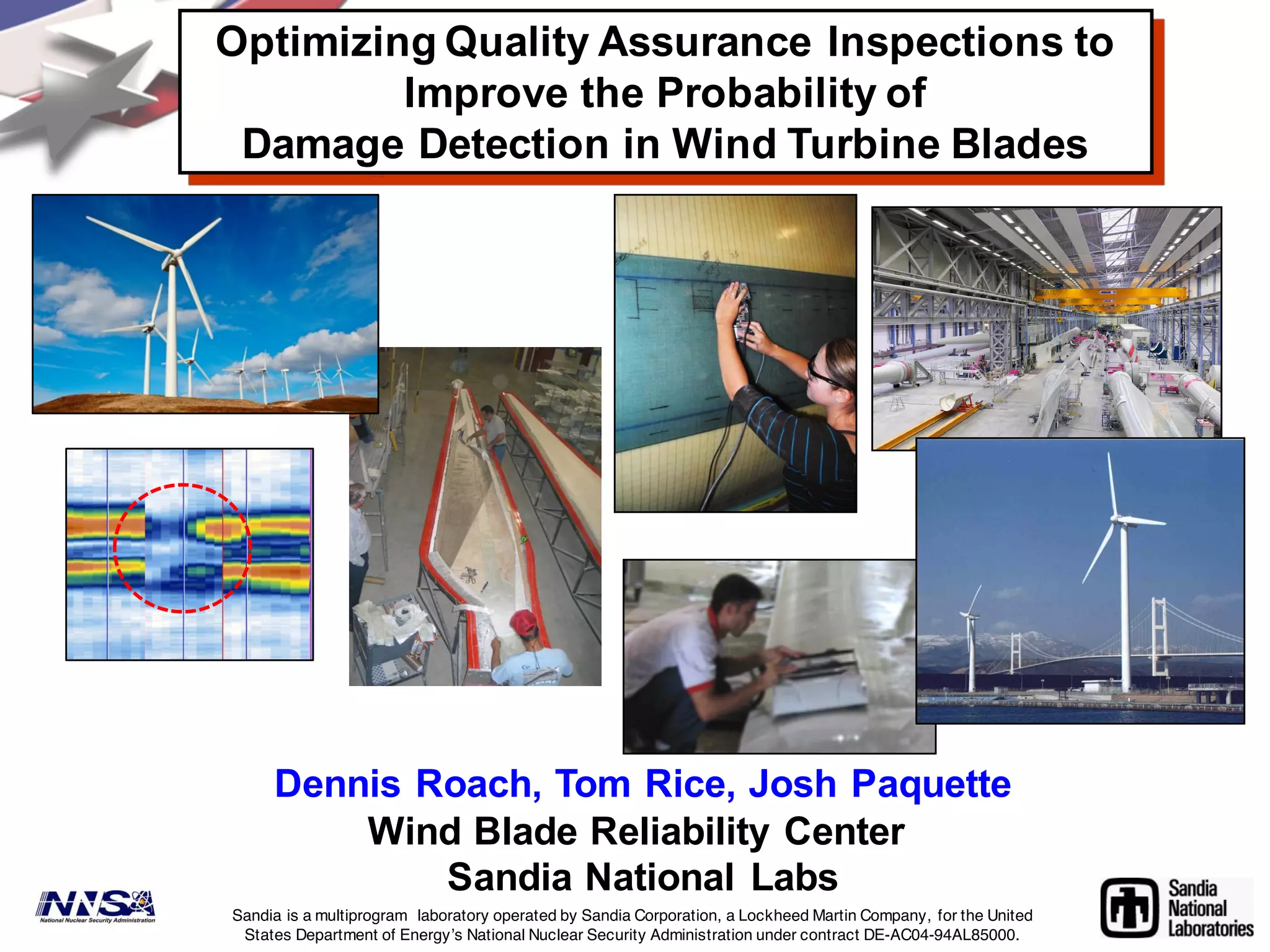
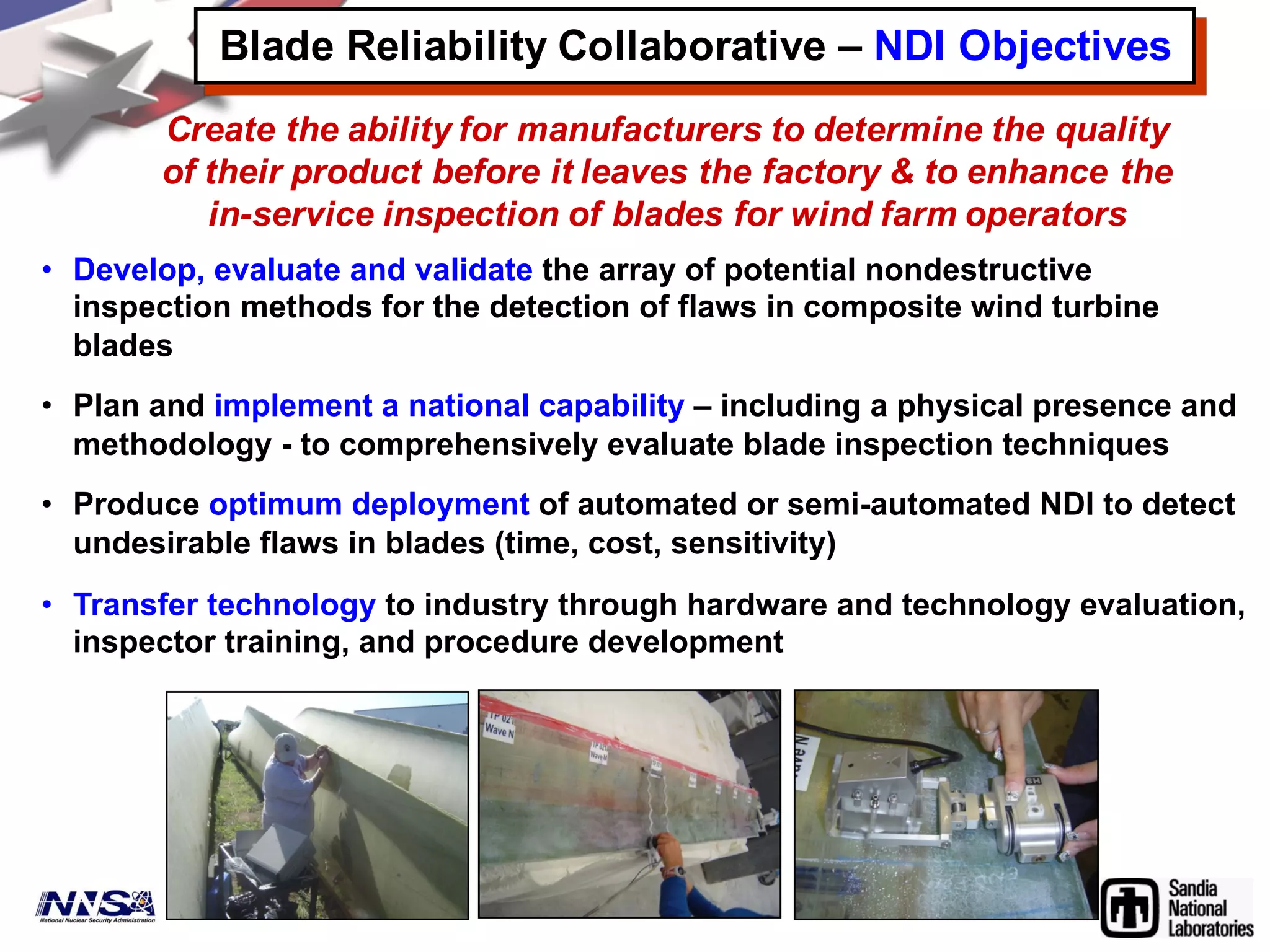
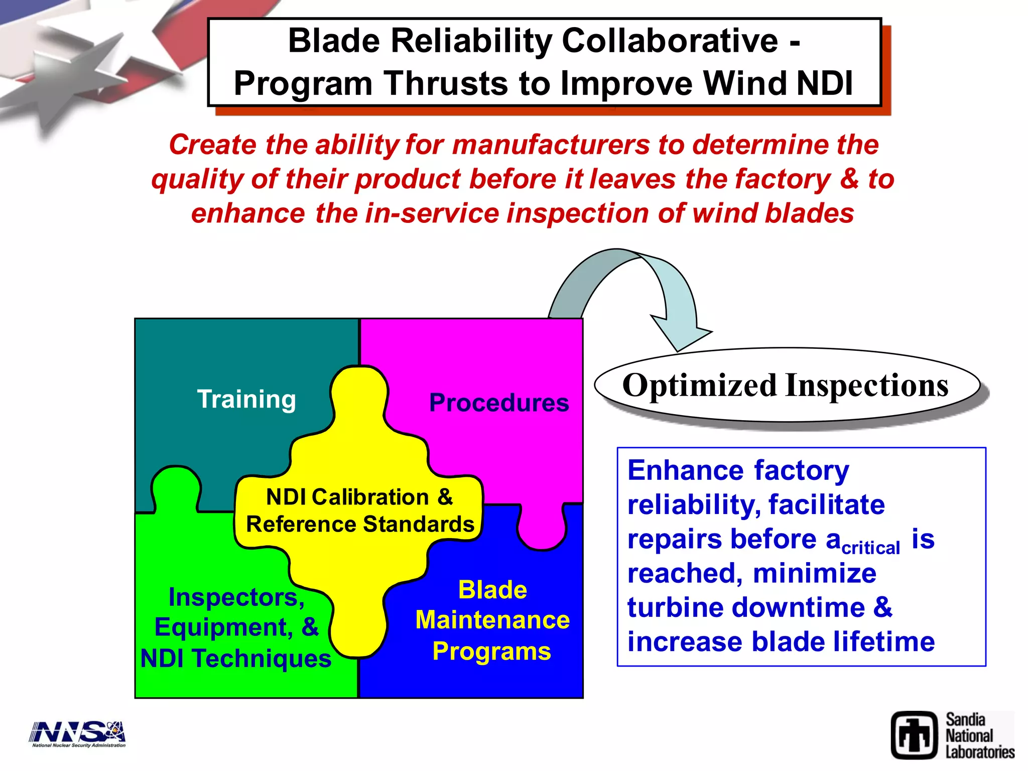
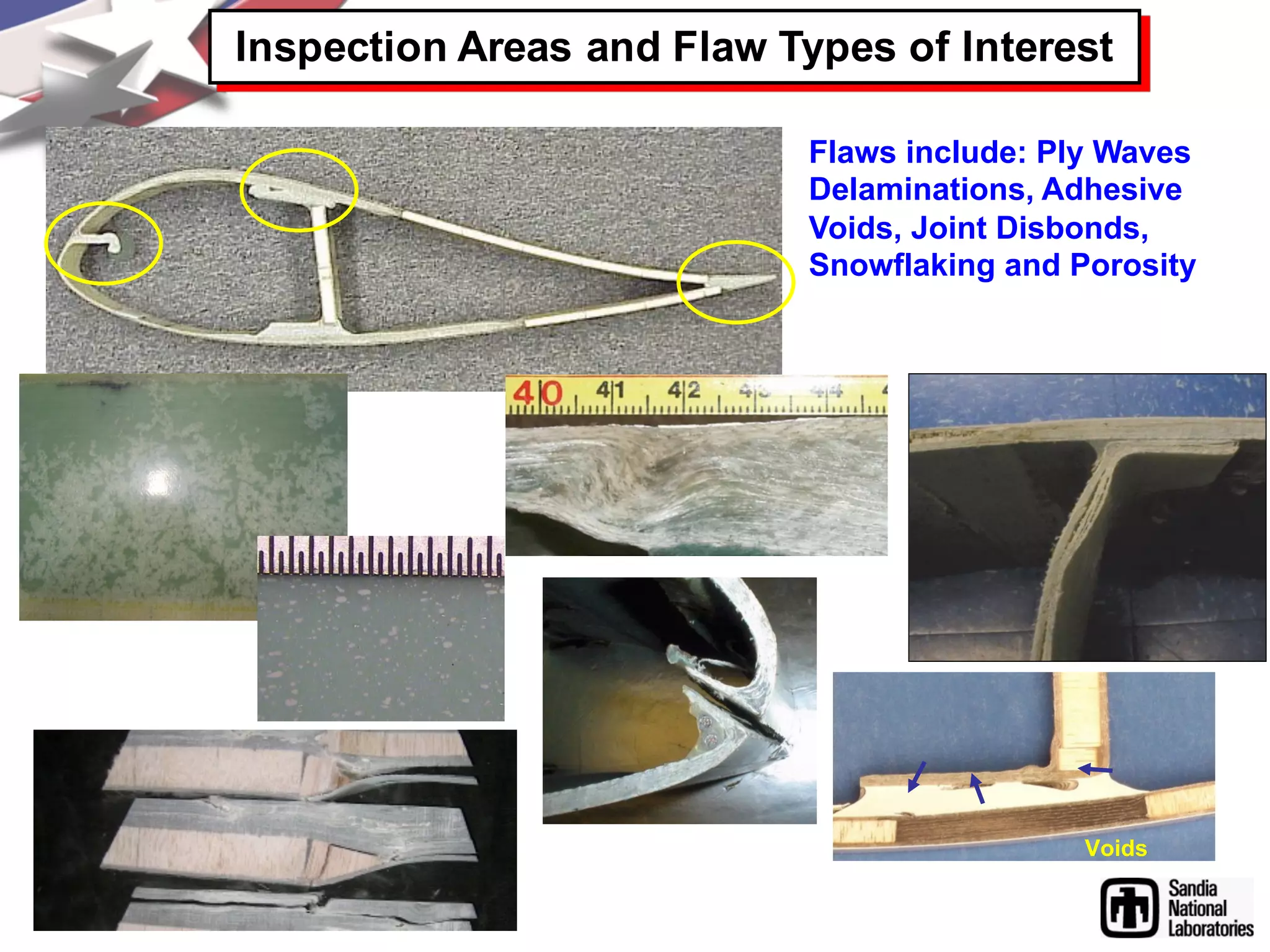
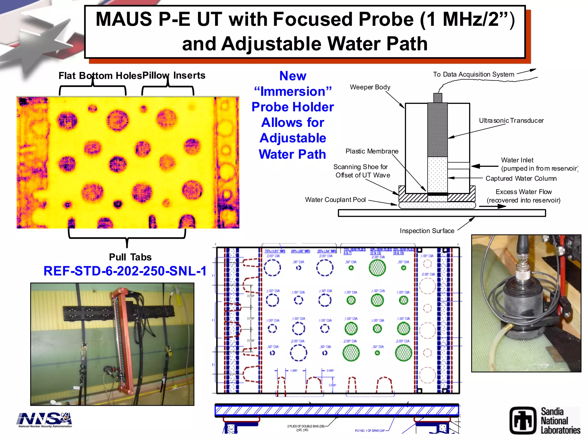
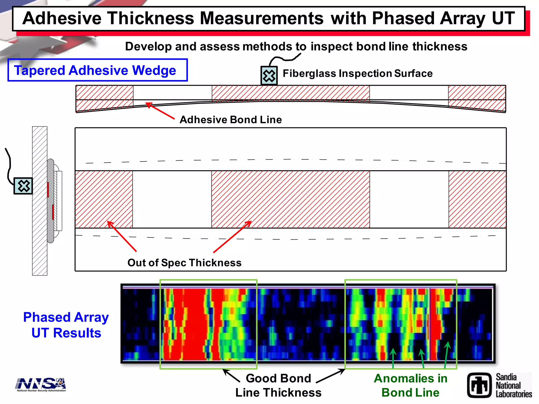
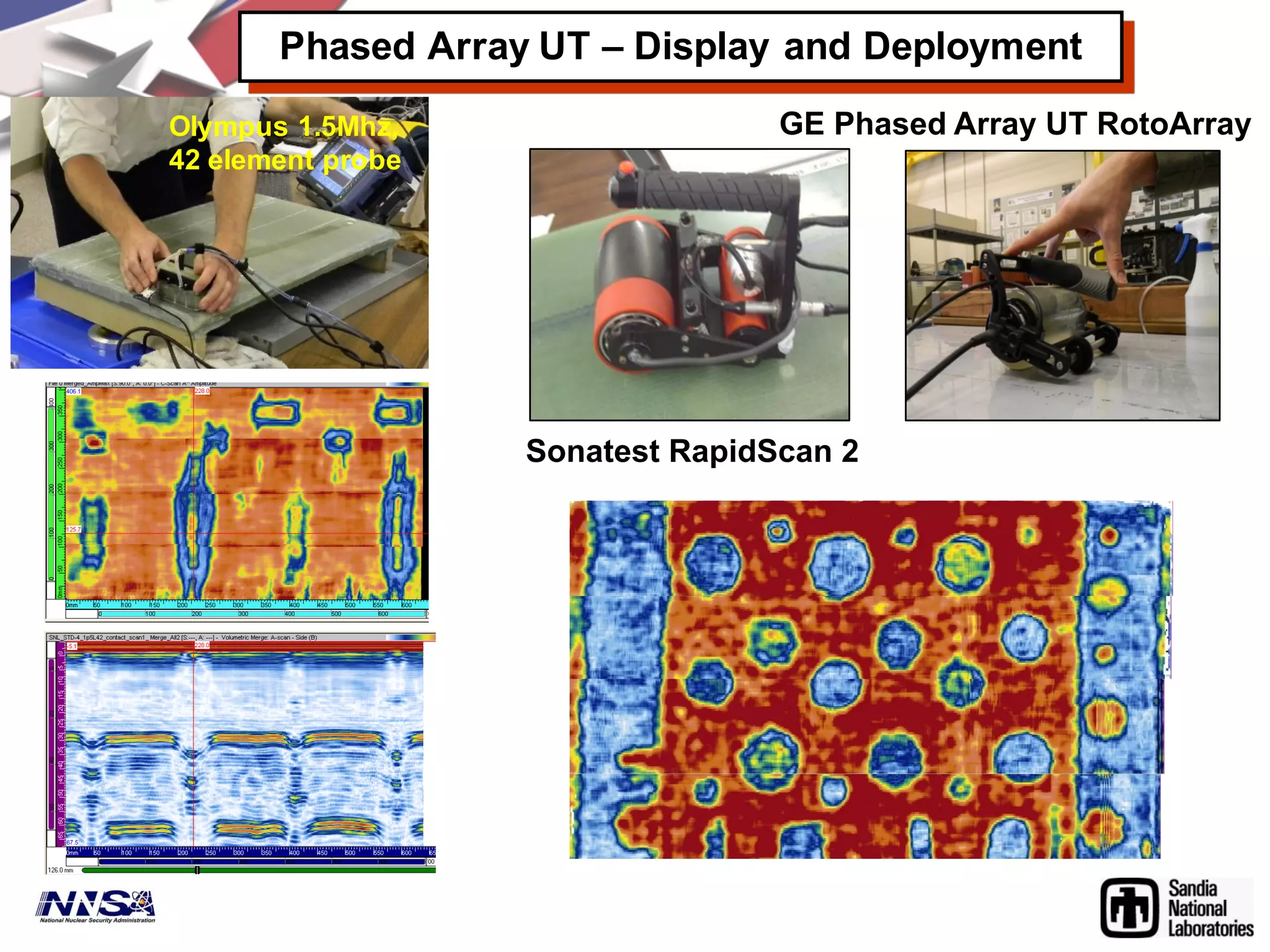
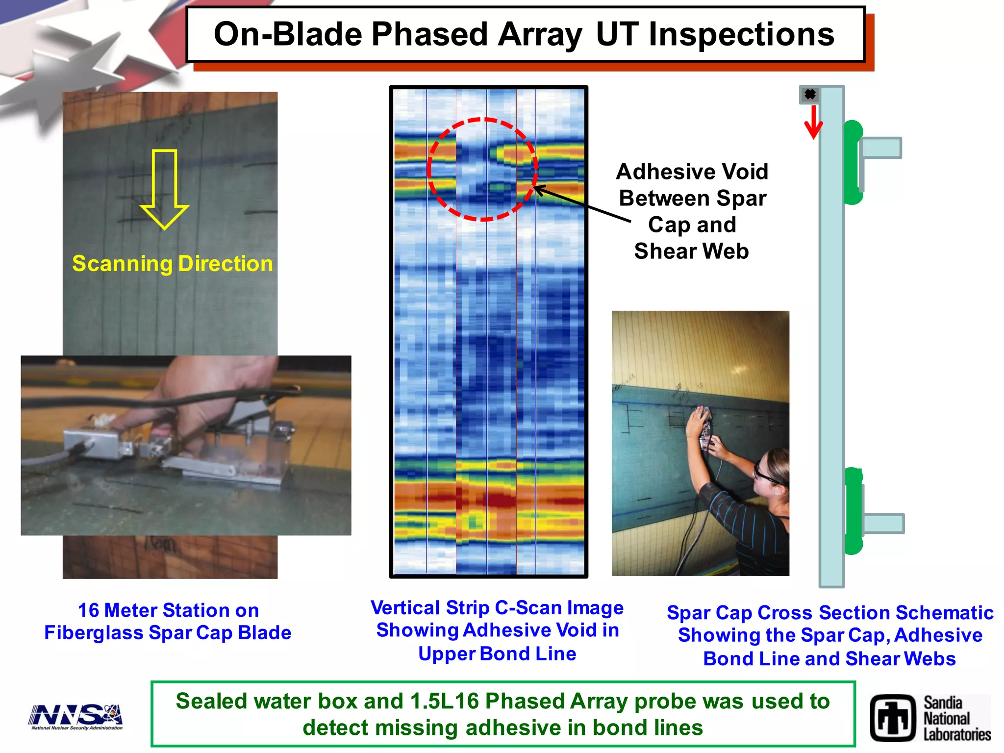
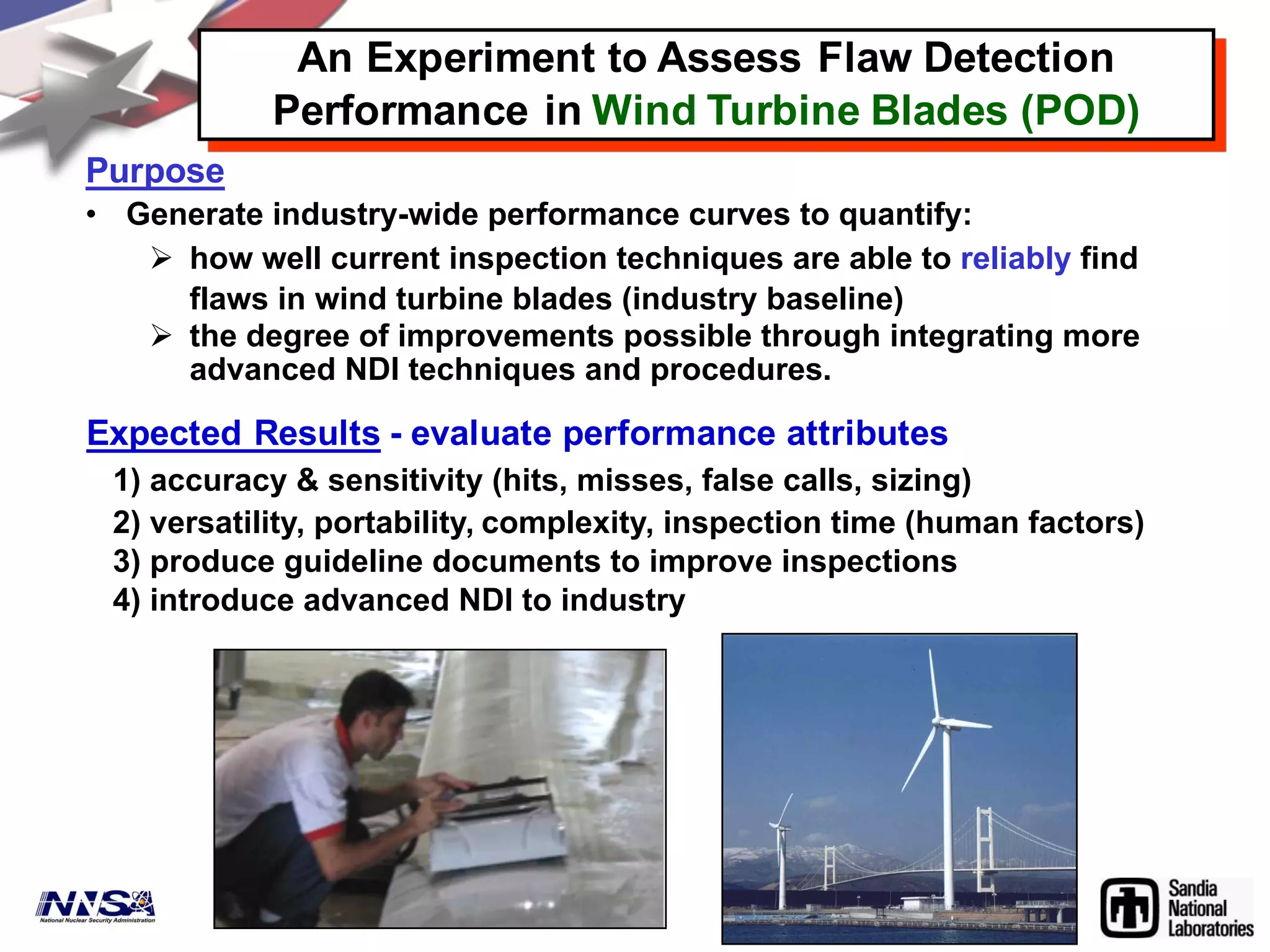
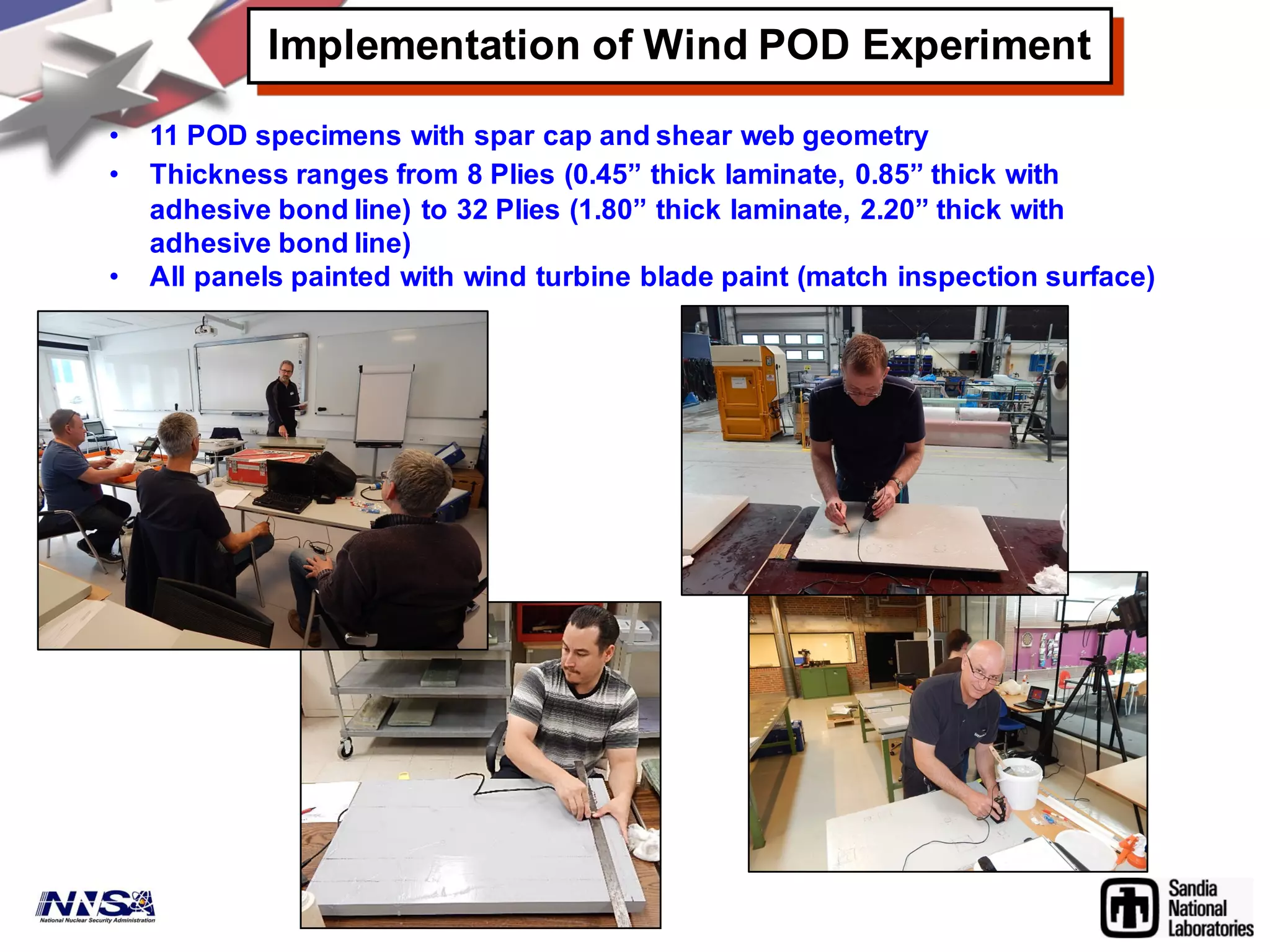
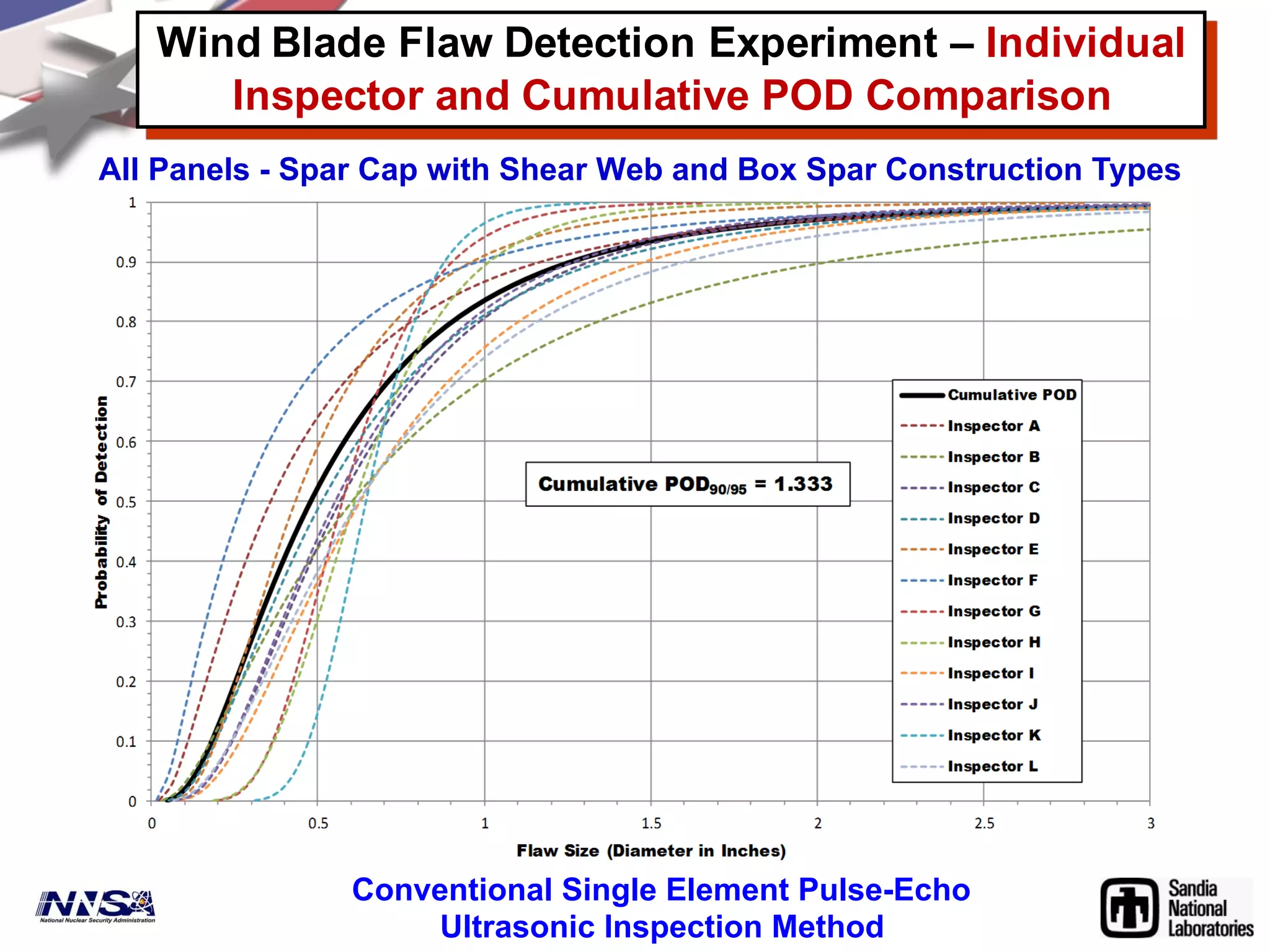
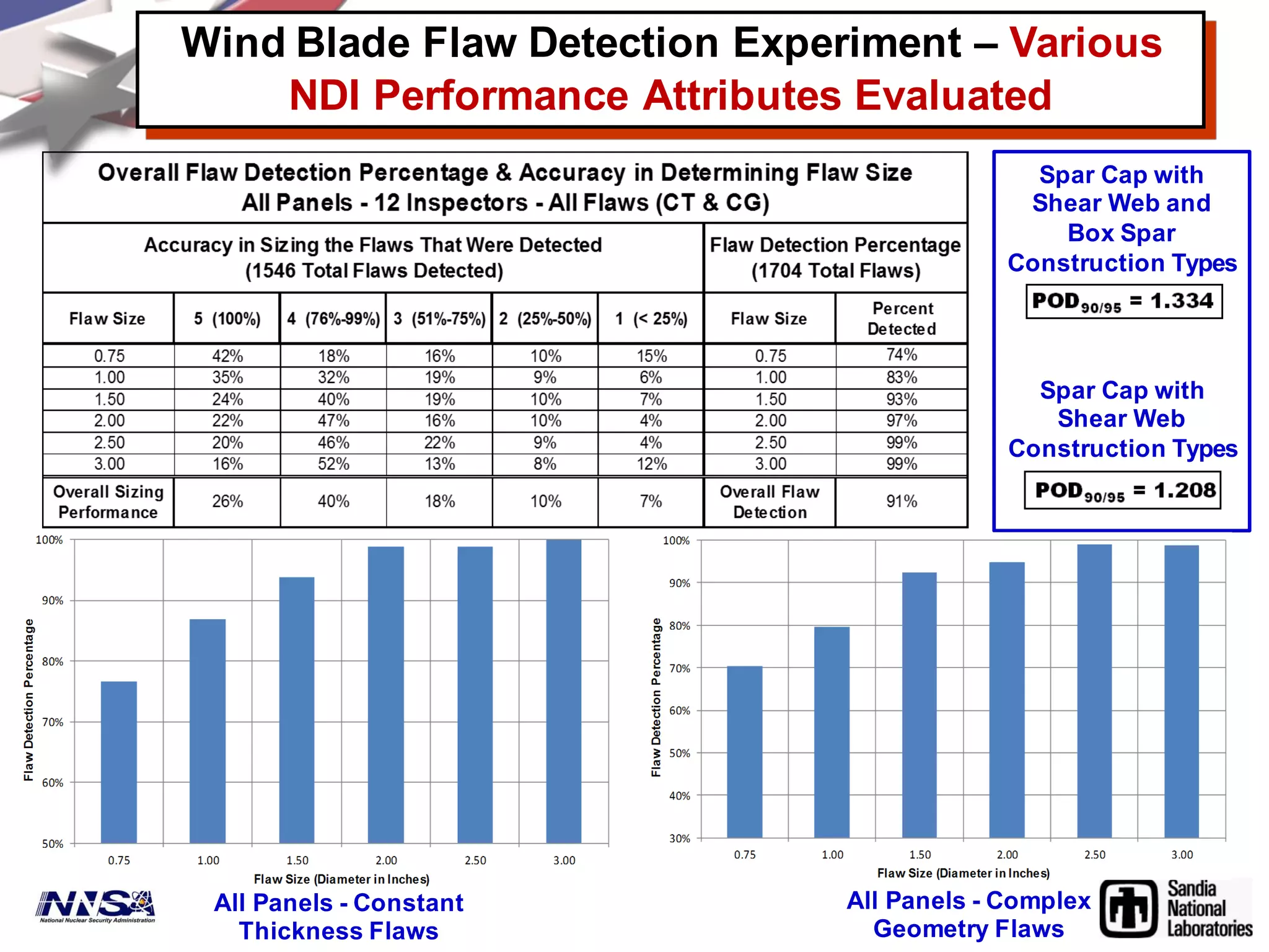
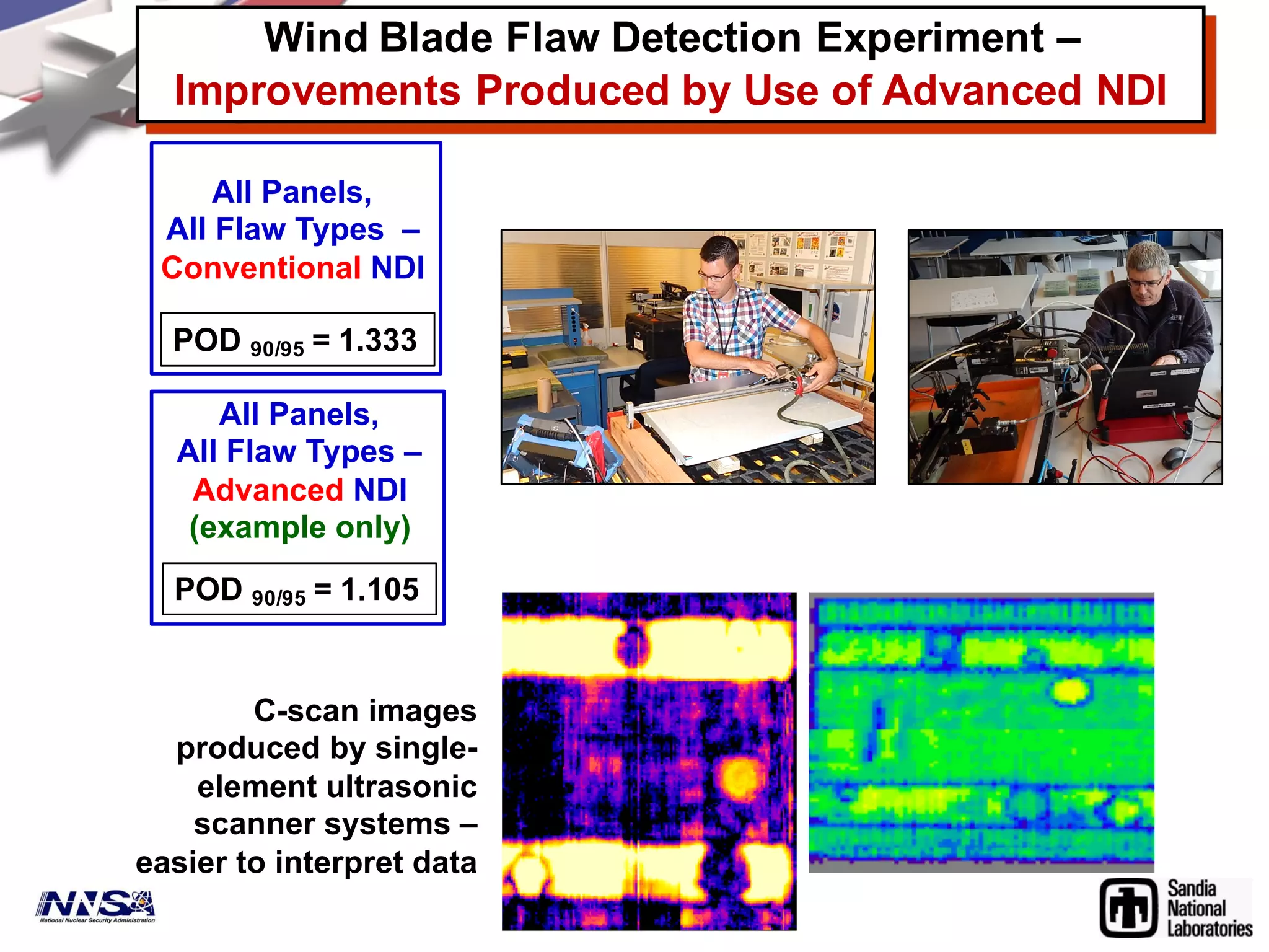
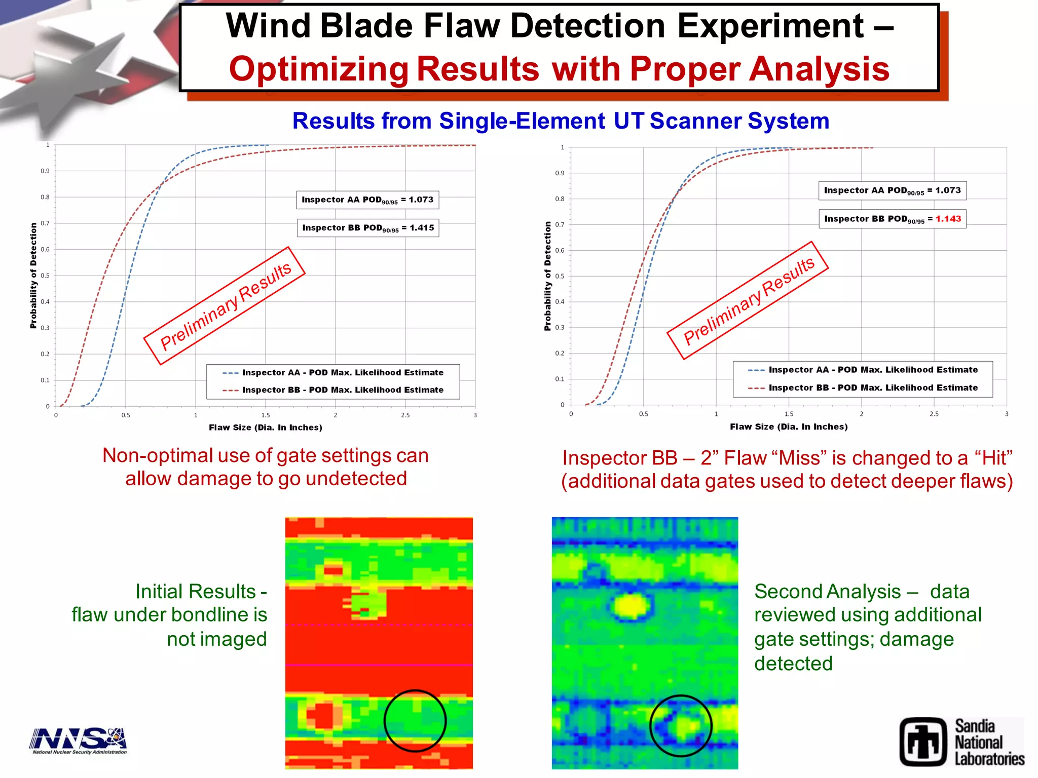
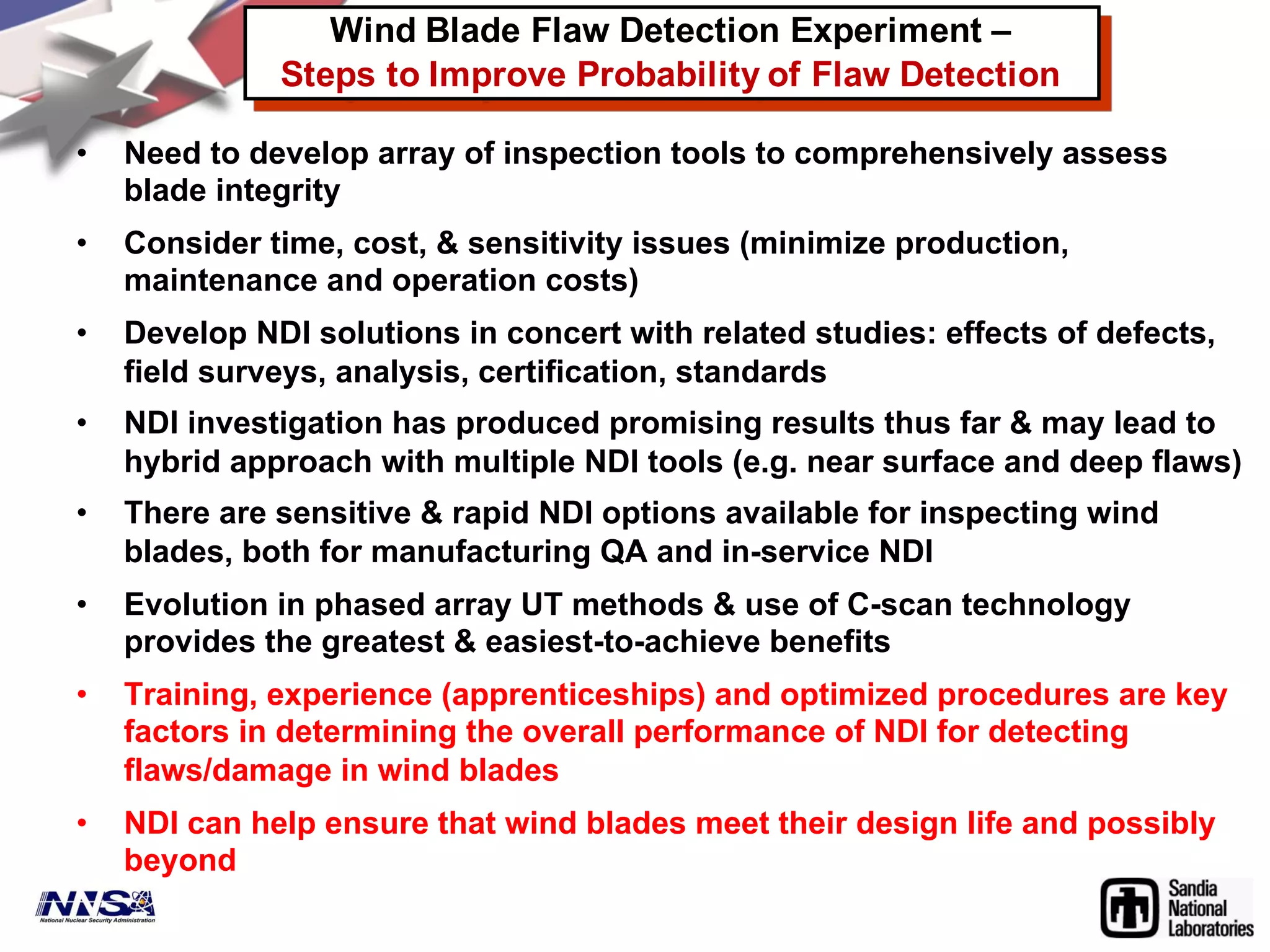
Sandia National Laboratories is working with industry partners to develop and validate nondestructive inspection methods for detecting flaws in wind turbine blades. They conducted an experiment using representative blade samples containing realistic flaws to evaluate current inspection techniques and identify ways to improve flaw detection rates. The results showed that inspections could miss flaws but advanced techniques like phased array ultrasound offered improvements over conventional ultrasound. Optimizing factors like inspector training and standardized procedures was also important to ensure reliable inspections.


