© Hyprotech 2002
Introduction to Heat Exchangers
Course objectives
What are exchangers for?
Exchanger types
How are they specified?
The design task
© Hyprotech 2002
Objectives
By the end of the course you will
• be familiar with the main exchanger types
• know which is likely to be the best type for a given
application
• understand what are the key factors in exchanger
design
• be able to estimate the size and cost of key exchanger
types
• have the background necessary to start using
commercial exchanger design software
• be an informed purchaser of heat exchangers
© Hyprotech 2002
Lecture series
• Introduction to heat
exchangers
• Selection of the best
type for a given
application
• Selection of right
shell and tube
• Design of shell and
tube
Q = U A ∆T
© Hyprotech 2002
Contents
• Why we need heat exchangers
• The basics of their design
• Some general features of exchangers
• Different types of exchanger
• The design process
© Hyprotech 2002
Example of an exchanger
Bundle for shell-and-tube exchanger
© Hyprotech 2002
What are heat exchangers for?
• To get fluid streams to the right temperature
for the next process
– reactions often require feeds at high temp.
• To condense vapours
• To evaporate liquids
• To recover heat to use elsewhere
• To reject low-grade heat
• To drive a power cycle
© Hyprotech 2002
Feed-effluent exchanger
Feed-effluent
exchanger
Exothermic reaction
Heat recovery
© Hyprotech 2002
Distillation
Bottom product
Feed
Top product
Reflux condenser
Reboiler
Column
© Hyprotech 2002
Typical crude oil distillation
E2
E1
E3
E4
E5 E6
E2
E5
Storage
Kerosene
Desalter
Top pump
around
Top pump
around
Naphtha
and gases
Kerosene
Furnace
Reduced crude
Light
gas oil
Heavy
gas oil
Reduced
crude
Heavy gas oil
Light gas oil
Bottom pump
around
Distillationtower
Bottom
pump
around
© Hyprotech 2002
Power cycle
Boiler Condenser
Steam turbine
Feedwater
heater
© Hyprotech 2002
Q = U A ∆T
We have thermal resistances in series
Thot
Tcold
1 1 1
U
r
y
r
cold
cold
w
w
hot
hot
= + + + +
α λ α
yw
© Hyprotech 2002
Heat utilities
• Hot utilities
– Boiler generating service steam (maybe a
combined heat and power plant)
– Direct fired heaters (furnace)
– Electric heaters
• Cold utilities
– Cooling tower (wet or dry) providing service
cooling water
– Direct air-cooled heat exchanger
© Hyprotech 2002
Thermal integration
or process integration
• Reducing the hot and cold utility needs by
interchanging heat between process
streams
• If the plant needs are primarily heat,
thermal integration is usually by “pinch
technology” - Software HX-Net
• If the plant is concerned with heat and
work, pinch technology is supplemented
with “exergy analysis”
© Hyprotech 2002
Local and mean values
• “Overall” means from the hot side to the
cold side including all resistances
• However it is still at a particular point in the
exchanger: i.e. it is local
• Hence you can have a local, overall
coefficient
LOCALLY
FOR WHOLE EXCHANGER
mTmT TAUQ
TUq
∆=
∆=


© Hyprotech 2002
Integrating over the exchanger area
Local equation
Rearranging
and integrating





q
dQ
dA
U T
dQ
T
UdA
dQ
T
UdA
Q AT T
= =
=
=∫ ∫
∆
∆
∆
dQ
dA
Total area AT
© Hyprotech 2002
Definitions of mean values
From previous slides
Comparing the two sides


Q
T
U A
dQ
T
UdA
T
m
m T
Q AT T
∆
∆
=
=∫ ∫
1 1
∆ ∆T Q
dQ
Tm T Q
= ∫

U
A
UdAm
T AT
= ∫
1
© Hyprotech 2002
Special case where Ts are linear with Q
• Eqn. integrates to
give log. mean
temperature
difference - LMTD ∆Ta
∆ ∆
∆ ∆
∆ ∆
T T
T T
T T
m LM
a b
a b
= =
−
ln( / ) ∆Tb
QTemperature
© Hyprotech 2002
Multipass exchangers
• For single-phase duties,
theoretical correction
factors, FT, have been
derived
• FT values are less than 1
• Do not design for FT less
than 0.8
Q
Temp.
T1
T2
t1
t2
∆ ∆T F Tm T LM=
© Hyprotech 2002
Typical FT correction factor curves
For shell and tube with 2 or more tube-side passes
T, t = Shell / tube side
1, 2 = inlet / outlet
P
t t
T t
R
T T
t t
=
−
−
=
−
−
2 1
1 1
1 2
2 1
;
Curves are for different values of R
© Hyprotech 2002
Thermal effectiveness
ε =
−
−
T T
T T
in out
in in
1 1
1 2
, ,
, ,
Stream temperature rise divided by the
theoretically maximum possible
temperature rise
T1,in T1,out
T2,out
T2,in
© Hyprotech 2002
Compactness
• Can be measured by the heat-transfer area
per unit volume or by channel size
• Conventional exchangers (shell and tube)
have channel size of 10 to 30 mm giving
about 100m2
/m3
• Plate-type exchangers have typically 5mm
channel size with more than 200m2
/m3
• More compact types available
© Hyprotech 2002
Compactness
m2
/m3
100 1000 10 000
Hydraulic diameter, mm
60 10 1 0.1
Shell-&-tube
Plate
Plate fin
Car radiator
Special
Human lungs
© Hyprotech 2002
Main categories of exchanger
Heat exchangers
Recuperator
s
Regenerators
Wall separating streamsWall separating streams Direct contact
Most heat exchangers have two streams, hot
and cold, but some have more than two
© Hyprotech 2002
Recuperators/regenerators
RecuperativeRecuperative
Has separate flow paths for each
fluid which flow simultaneously
through the exchanger
transferring heat between the
streams
RegenerativeRegenerative
Has a single flow path which the hot
and cold fluids alternately pass
through.
Rotating wheel
© Hyprotech 2002
Double Pipe
Simplest type has one tube inside another - inner
tube may have longitudinal fins on the outside
However, most have a
number of tubes in the outer
tube - can have very many
tubes thus becoming a shell-
and-tube
© Hyprotech 2002
Shell and Tube
Typical shell and tube exchanger as used in the
process industry
© Hyprotech 2002
Shell-side flow
© Hyprotech 2002
Complete shell-and-tube
© Hyprotech 2002
Plate and frame
• Plates hung vertically and
clamped in a press or frame.
• Gaskets direct the streams
between alternate plates and
prevent external leakage
• Plates made of stainless steel or
higher quality material
• Plates corrugated to give points
of support and increase heat
transfer
© Hyprotech 2002
Chevron Washboard
Plate types
Corrugations on plate
improve heart transfer
give rigidity
Many points of
contact and a
tortuous flow path
© Hyprotech 2002
General view of
plate exchanger
“Plate exchanger”
normally refers to
a gasketted plate-
and-frame
exchanger
© Hyprotech 2002
Flow Arrangement within a PHE
Alternate plates (often same plate types inverted)
Gaskets
arranged for
each stream to
flow between
alternate plates
© Hyprotech 2002
Air-cooled exchanger
• Air blown across finned tubes (forcedAir blown across finned tubes (forced
draught type)draught type)
• Can suck air across (induced draught)Can suck air across (induced draught)
Finned tubes
© Hyprotech 2002
ACHE bundle
© Hyprotech 2002
Plate-fin exchanger
• Made up of flat plates (parting sheets) and
corrugated sheets which form fins
• Brazed by heating in vacuum furnace
© Hyprotech 2002
Can have many streams
7 or more streams are typical
© Hyprotech 2002
Typical plate-fin
© Hyprotech 2002
Spiral (plate)
Good for streams with large solids
© Hyprotech 2002
Cooling Towers
• Large shell with packing at the bottom over
which water is sprayed
• Cooling by air flow and evaporation
• Air flow driven by forced or natural
convection
• Need to continuously make up the cooling
water lost by evaporation
© Hyprotech 2002
Agitated Vessel• Used for batch
heating or cooling
of fluids
• An agitator and
baffles promote
mixing
• A range of
agitators are used
• Often used for
batch chemical
reaction
© Hyprotech 2002
Proprietary types
• Types described so far are generic types
• These can be made by any company with
necessary skills (no real patent protection)
• There are now many special, proprietary
exchangers made by one company or a
small number of companies under licence
• One example is the “printed circuit
exchanger” by Heatric
© Hyprotech 2002
Printed circuit heat exchanger
• Plates are etched to
give flow channels
• Stacked to form
exchanger block
• Block diffusion welded
under high pressure
and temperature
• Bond formed is as
strong as the metal
itself
© Hyprotech 2002
Printed circuit exchanger
Note that “compact” does not
mean small but means large
surface area per unit volume
© Hyprotech 2002
Distribution of types
in terms of market value in Europe
Shell & Tube
42%
Other Tubular
5%
Plate & Frame
13%
Other Plate
4%
Other Proprietary
2%
Air Coolers
10%
Cooling Towers
9%
Waste Heat
Boilers
5%
Other Heat
Recovery
10%
© Hyprotech 2002
Preliminary points on selection
• Tubes and cylinders can withstand higher
pressures than plates
• If exchangers can be built with a variety of
materials, then it is more likely that you can
find a metal which will cope with extreme
temperatures or corrosive fluids
• More specialist exchangers have fewer
suppliers, longer delivery times and must be
repaired by experts
• S&Ts cannot normally give high thermal
effectiveness, ε
© Hyprotech 2002
Design sequence
• Design the process flow flow-sheet
• Specify the heat exchanger requirements
• Select the best exchanger type for the job
• Thermal design of exchanger
• Mechanical design of exchanger
Looping back may be necessary at any
stage but can be difficult because of the
project timetable
© Hyprotech 2002
Who does what?
• Design the process flow flow-
sheet
• Specify the heat exchanger
requirements
• Select the best exchanger type
for the job
• Thermal design of exchanger
• Mechanical design of exchanger
Processor/
end user
Contractor
Manufacturer
© Hyprotech 2002
Exchanger specification
• Heat load (duty) along with the terminal
temperatures of the streams
• Maximum pressure drop each streams
– liquids - 0.5 bar
– gases/vapours below 2bar - 10% of inlet pressure
• Design pressures and temperatures
• Size/weight constraints
• Standards to apply
– General standards like ISO, TEMA, ASME etc
– Companies own standards
• Other requirements
© Hyprotech 2002
The designer must supply an
exchanger which
• Meets the stated specification
• Has reasonable initial costs and operating
costs (most exchangers are bought on the
basis of the cheapest tender)
• Has a reasonable lifetime
– no damaging vibration
– no thermal fatigue
– no unexpected fouling or corrosion

Introduction to heat_exchangers

  • 1.
    © Hyprotech 2002 Introductionto Heat Exchangers Course objectives What are exchangers for? Exchanger types How are they specified? The design task
  • 2.
    © Hyprotech 2002 Objectives Bythe end of the course you will • be familiar with the main exchanger types • know which is likely to be the best type for a given application • understand what are the key factors in exchanger design • be able to estimate the size and cost of key exchanger types • have the background necessary to start using commercial exchanger design software • be an informed purchaser of heat exchangers
  • 3.
    © Hyprotech 2002 Lectureseries • Introduction to heat exchangers • Selection of the best type for a given application • Selection of right shell and tube • Design of shell and tube Q = U A ∆T
  • 4.
    © Hyprotech 2002 Contents •Why we need heat exchangers • The basics of their design • Some general features of exchangers • Different types of exchanger • The design process
  • 5.
    © Hyprotech 2002 Exampleof an exchanger Bundle for shell-and-tube exchanger
  • 6.
    © Hyprotech 2002 Whatare heat exchangers for? • To get fluid streams to the right temperature for the next process – reactions often require feeds at high temp. • To condense vapours • To evaporate liquids • To recover heat to use elsewhere • To reject low-grade heat • To drive a power cycle
  • 7.
    © Hyprotech 2002 Feed-effluentexchanger Feed-effluent exchanger Exothermic reaction Heat recovery
  • 8.
    © Hyprotech 2002 Distillation Bottomproduct Feed Top product Reflux condenser Reboiler Column
  • 9.
    © Hyprotech 2002 Typicalcrude oil distillation E2 E1 E3 E4 E5 E6 E2 E5 Storage Kerosene Desalter Top pump around Top pump around Naphtha and gases Kerosene Furnace Reduced crude Light gas oil Heavy gas oil Reduced crude Heavy gas oil Light gas oil Bottom pump around Distillationtower Bottom pump around
  • 10.
    © Hyprotech 2002 Powercycle Boiler Condenser Steam turbine Feedwater heater
  • 11.
    © Hyprotech 2002 Q= U A ∆T We have thermal resistances in series Thot Tcold 1 1 1 U r y r cold cold w w hot hot = + + + + α λ α yw
  • 12.
    © Hyprotech 2002 Heatutilities • Hot utilities – Boiler generating service steam (maybe a combined heat and power plant) – Direct fired heaters (furnace) – Electric heaters • Cold utilities – Cooling tower (wet or dry) providing service cooling water – Direct air-cooled heat exchanger
  • 13.
    © Hyprotech 2002 Thermalintegration or process integration • Reducing the hot and cold utility needs by interchanging heat between process streams • If the plant needs are primarily heat, thermal integration is usually by “pinch technology” - Software HX-Net • If the plant is concerned with heat and work, pinch technology is supplemented with “exergy analysis”
  • 14.
    © Hyprotech 2002 Localand mean values • “Overall” means from the hot side to the cold side including all resistances • However it is still at a particular point in the exchanger: i.e. it is local • Hence you can have a local, overall coefficient LOCALLY FOR WHOLE EXCHANGER mTmT TAUQ TUq ∆= ∆=  
  • 15.
    © Hyprotech 2002 Integratingover the exchanger area Local equation Rearranging and integrating      q dQ dA U T dQ T UdA dQ T UdA Q AT T = = = =∫ ∫ ∆ ∆ ∆ dQ dA Total area AT
  • 16.
    © Hyprotech 2002 Definitionsof mean values From previous slides Comparing the two sides   Q T U A dQ T UdA T m m T Q AT T ∆ ∆ = =∫ ∫ 1 1 ∆ ∆T Q dQ Tm T Q = ∫  U A UdAm T AT = ∫ 1
  • 17.
    © Hyprotech 2002 Specialcase where Ts are linear with Q • Eqn. integrates to give log. mean temperature difference - LMTD ∆Ta ∆ ∆ ∆ ∆ ∆ ∆ T T T T T T m LM a b a b = = − ln( / ) ∆Tb QTemperature
  • 18.
    © Hyprotech 2002 Multipassexchangers • For single-phase duties, theoretical correction factors, FT, have been derived • FT values are less than 1 • Do not design for FT less than 0.8 Q Temp. T1 T2 t1 t2 ∆ ∆T F Tm T LM=
  • 19.
    © Hyprotech 2002 TypicalFT correction factor curves For shell and tube with 2 or more tube-side passes T, t = Shell / tube side 1, 2 = inlet / outlet P t t T t R T T t t = − − = − − 2 1 1 1 1 2 2 1 ; Curves are for different values of R
  • 20.
    © Hyprotech 2002 Thermaleffectiveness ε = − − T T T T in out in in 1 1 1 2 , , , , Stream temperature rise divided by the theoretically maximum possible temperature rise T1,in T1,out T2,out T2,in
  • 21.
    © Hyprotech 2002 Compactness •Can be measured by the heat-transfer area per unit volume or by channel size • Conventional exchangers (shell and tube) have channel size of 10 to 30 mm giving about 100m2 /m3 • Plate-type exchangers have typically 5mm channel size with more than 200m2 /m3 • More compact types available
  • 22.
    © Hyprotech 2002 Compactness m2 /m3 1001000 10 000 Hydraulic diameter, mm 60 10 1 0.1 Shell-&-tube Plate Plate fin Car radiator Special Human lungs
  • 23.
    © Hyprotech 2002 Maincategories of exchanger Heat exchangers Recuperator s Regenerators Wall separating streamsWall separating streams Direct contact Most heat exchangers have two streams, hot and cold, but some have more than two
  • 24.
    © Hyprotech 2002 Recuperators/regenerators RecuperativeRecuperative Hasseparate flow paths for each fluid which flow simultaneously through the exchanger transferring heat between the streams RegenerativeRegenerative Has a single flow path which the hot and cold fluids alternately pass through. Rotating wheel
  • 25.
    © Hyprotech 2002 DoublePipe Simplest type has one tube inside another - inner tube may have longitudinal fins on the outside However, most have a number of tubes in the outer tube - can have very many tubes thus becoming a shell- and-tube
  • 26.
    © Hyprotech 2002 Shelland Tube Typical shell and tube exchanger as used in the process industry
  • 27.
  • 28.
  • 29.
    © Hyprotech 2002 Plateand frame • Plates hung vertically and clamped in a press or frame. • Gaskets direct the streams between alternate plates and prevent external leakage • Plates made of stainless steel or higher quality material • Plates corrugated to give points of support and increase heat transfer
  • 30.
    © Hyprotech 2002 ChevronWashboard Plate types Corrugations on plate improve heart transfer give rigidity Many points of contact and a tortuous flow path
  • 31.
    © Hyprotech 2002 Generalview of plate exchanger “Plate exchanger” normally refers to a gasketted plate- and-frame exchanger
  • 32.
    © Hyprotech 2002 FlowArrangement within a PHE Alternate plates (often same plate types inverted) Gaskets arranged for each stream to flow between alternate plates
  • 33.
    © Hyprotech 2002 Air-cooledexchanger • Air blown across finned tubes (forcedAir blown across finned tubes (forced draught type)draught type) • Can suck air across (induced draught)Can suck air across (induced draught) Finned tubes
  • 34.
  • 35.
    © Hyprotech 2002 Plate-finexchanger • Made up of flat plates (parting sheets) and corrugated sheets which form fins • Brazed by heating in vacuum furnace
  • 36.
    © Hyprotech 2002 Canhave many streams 7 or more streams are typical
  • 37.
  • 38.
    © Hyprotech 2002 Spiral(plate) Good for streams with large solids
  • 39.
    © Hyprotech 2002 CoolingTowers • Large shell with packing at the bottom over which water is sprayed • Cooling by air flow and evaporation • Air flow driven by forced or natural convection • Need to continuously make up the cooling water lost by evaporation
  • 40.
    © Hyprotech 2002 AgitatedVessel• Used for batch heating or cooling of fluids • An agitator and baffles promote mixing • A range of agitators are used • Often used for batch chemical reaction
  • 41.
    © Hyprotech 2002 Proprietarytypes • Types described so far are generic types • These can be made by any company with necessary skills (no real patent protection) • There are now many special, proprietary exchangers made by one company or a small number of companies under licence • One example is the “printed circuit exchanger” by Heatric
  • 42.
    © Hyprotech 2002 Printedcircuit heat exchanger • Plates are etched to give flow channels • Stacked to form exchanger block • Block diffusion welded under high pressure and temperature • Bond formed is as strong as the metal itself
  • 43.
    © Hyprotech 2002 Printedcircuit exchanger Note that “compact” does not mean small but means large surface area per unit volume
  • 44.
    © Hyprotech 2002 Distributionof types in terms of market value in Europe Shell & Tube 42% Other Tubular 5% Plate & Frame 13% Other Plate 4% Other Proprietary 2% Air Coolers 10% Cooling Towers 9% Waste Heat Boilers 5% Other Heat Recovery 10%
  • 45.
    © Hyprotech 2002 Preliminarypoints on selection • Tubes and cylinders can withstand higher pressures than plates • If exchangers can be built with a variety of materials, then it is more likely that you can find a metal which will cope with extreme temperatures or corrosive fluids • More specialist exchangers have fewer suppliers, longer delivery times and must be repaired by experts • S&Ts cannot normally give high thermal effectiveness, ε
  • 46.
    © Hyprotech 2002 Designsequence • Design the process flow flow-sheet • Specify the heat exchanger requirements • Select the best exchanger type for the job • Thermal design of exchanger • Mechanical design of exchanger Looping back may be necessary at any stage but can be difficult because of the project timetable
  • 47.
    © Hyprotech 2002 Whodoes what? • Design the process flow flow- sheet • Specify the heat exchanger requirements • Select the best exchanger type for the job • Thermal design of exchanger • Mechanical design of exchanger Processor/ end user Contractor Manufacturer
  • 48.
    © Hyprotech 2002 Exchangerspecification • Heat load (duty) along with the terminal temperatures of the streams • Maximum pressure drop each streams – liquids - 0.5 bar – gases/vapours below 2bar - 10% of inlet pressure • Design pressures and temperatures • Size/weight constraints • Standards to apply – General standards like ISO, TEMA, ASME etc – Companies own standards • Other requirements
  • 49.
    © Hyprotech 2002 Thedesigner must supply an exchanger which • Meets the stated specification • Has reasonable initial costs and operating costs (most exchangers are bought on the basis of the cheapest tender) • Has a reasonable lifetime – no damaging vibration – no thermal fatigue – no unexpected fouling or corrosion

Editor's Notes

  • #2 This first lecture is mainly qualitative as a lead in to the later lectures. It is very helpful to obtain samples from exchanger manufacturers to show the students. Possibilities are 
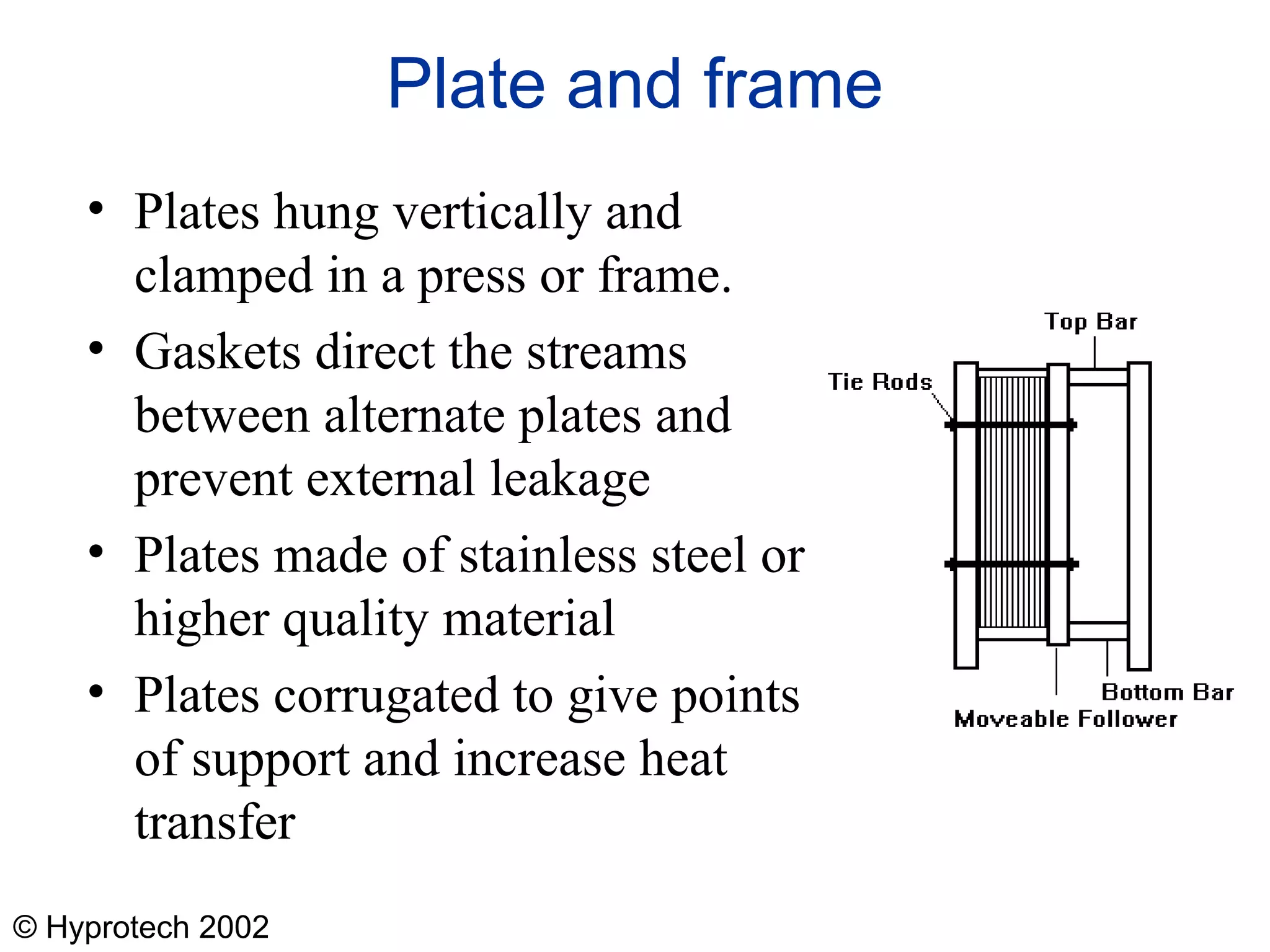
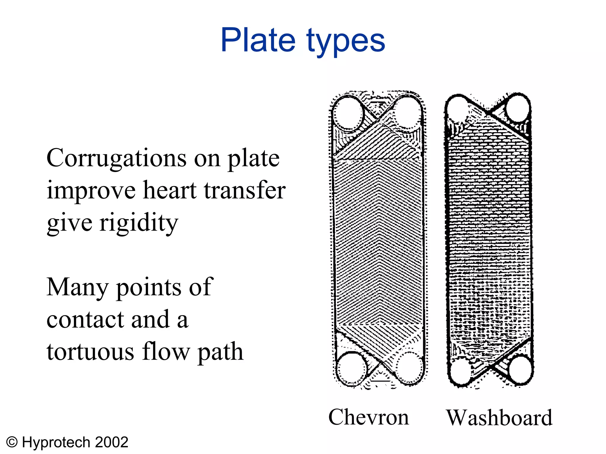
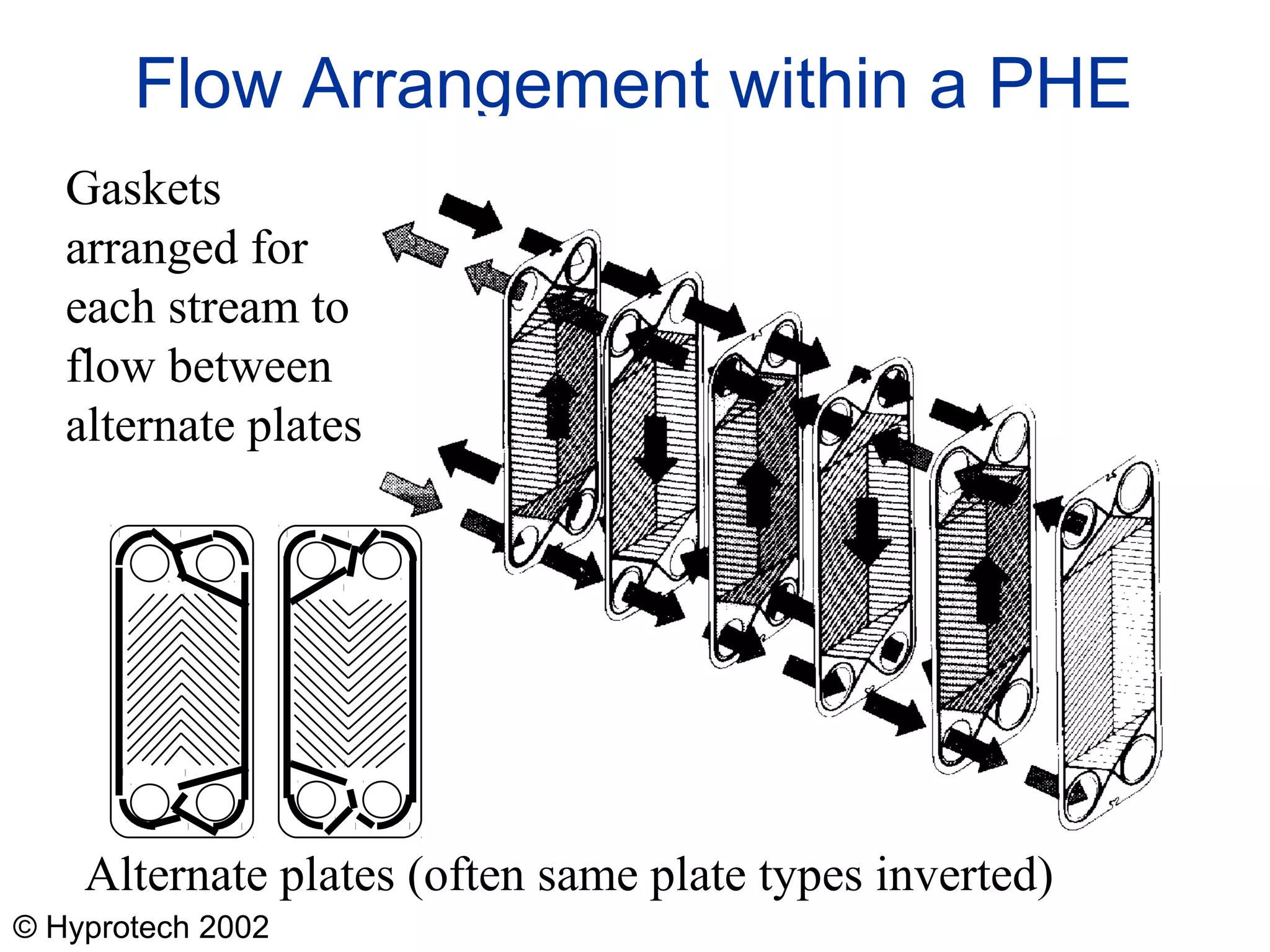
A small, chevron-type plate for a plate and frame exchanger 
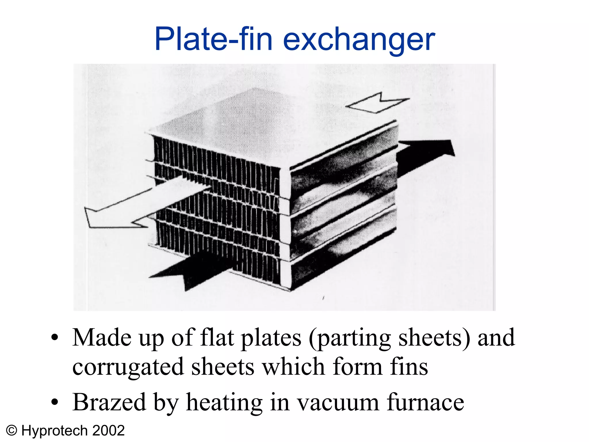
Various fin types for a plate-fin exchanger 
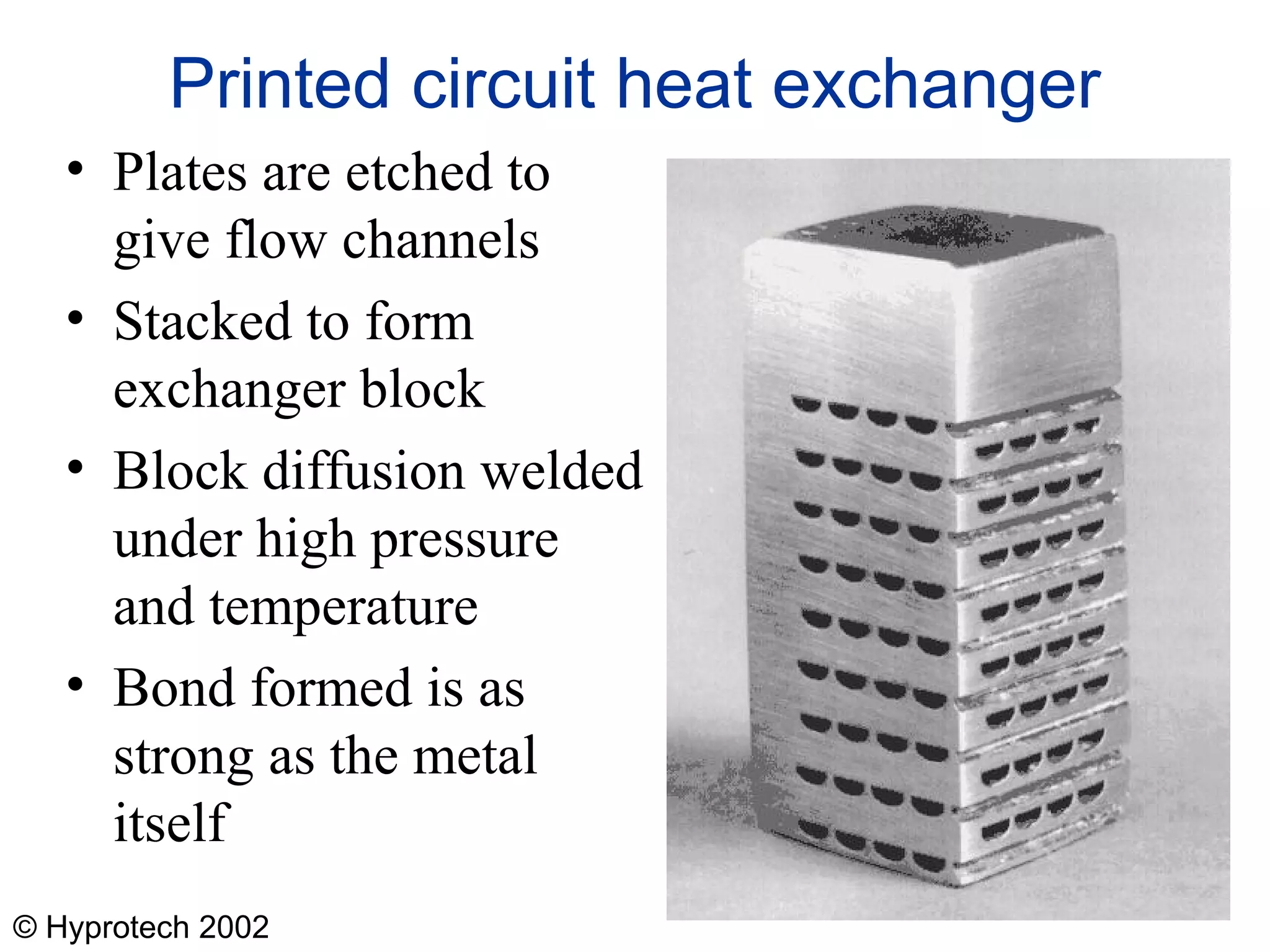
Etched plates and a sample block for a plate of a printed-circuit exchanger 
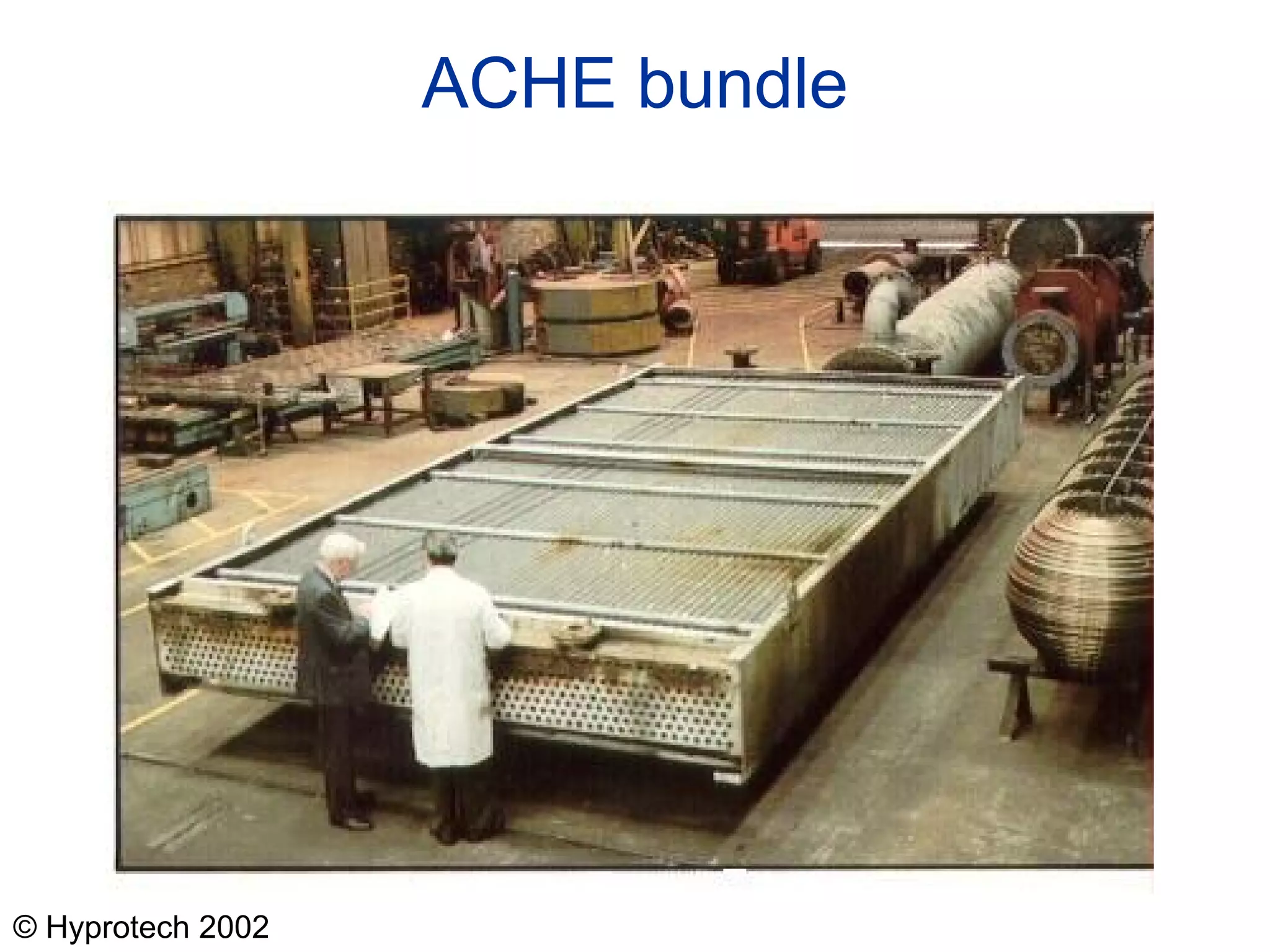
High-finned tube of the type used in air-cooled heat exchangers Samples of fins used in plate-fin exchangers Copyright Hyprotech UK Ltd holds the copyright to these lectures. Lecturers have permission to use the slides and other documents in their lectures and in handouts to students provided that they give full acknowledgement to Hyprotech. The information must not be incorporated into any publication without the written permission of Hyprotech.
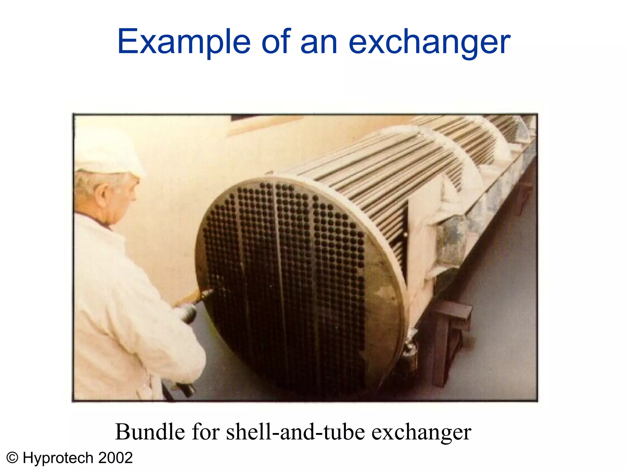
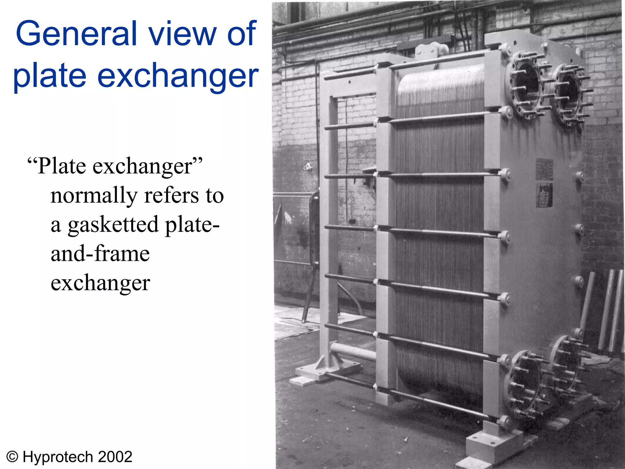
  • #6 Exchanger from Motherwell Bridge Thermal, Scotland Picture just to introduce a real exchanger early on.
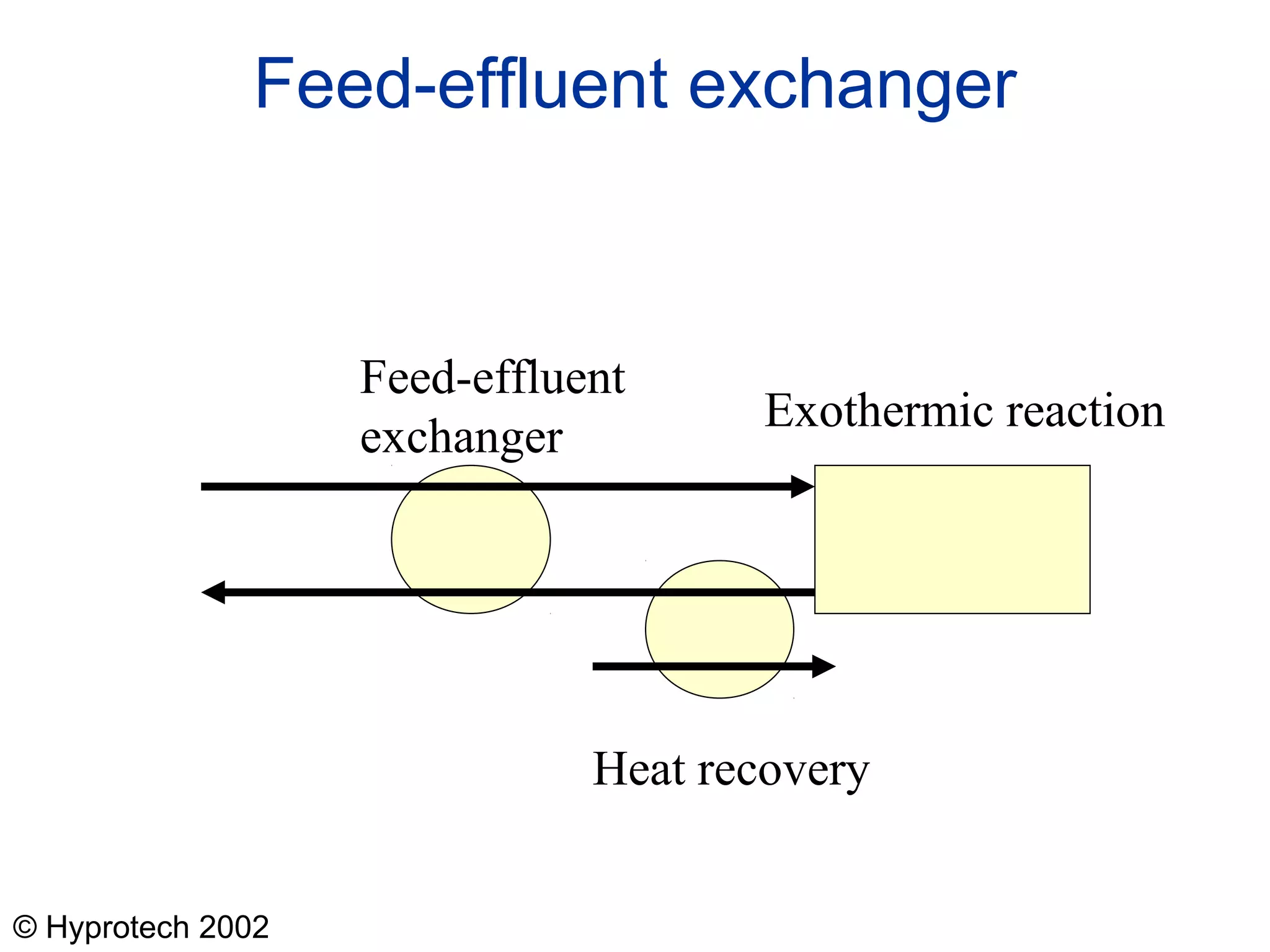
  • #8 Worth emphasising on this case that the feed-effluent exchanger needs a temperature difference to drive it, so there is a limit to what can be removed by the heat recovery exchanger exchanger. Typically. Feed-effluent exchangers involve a number of exchangers in series so that the picture is a simple case.
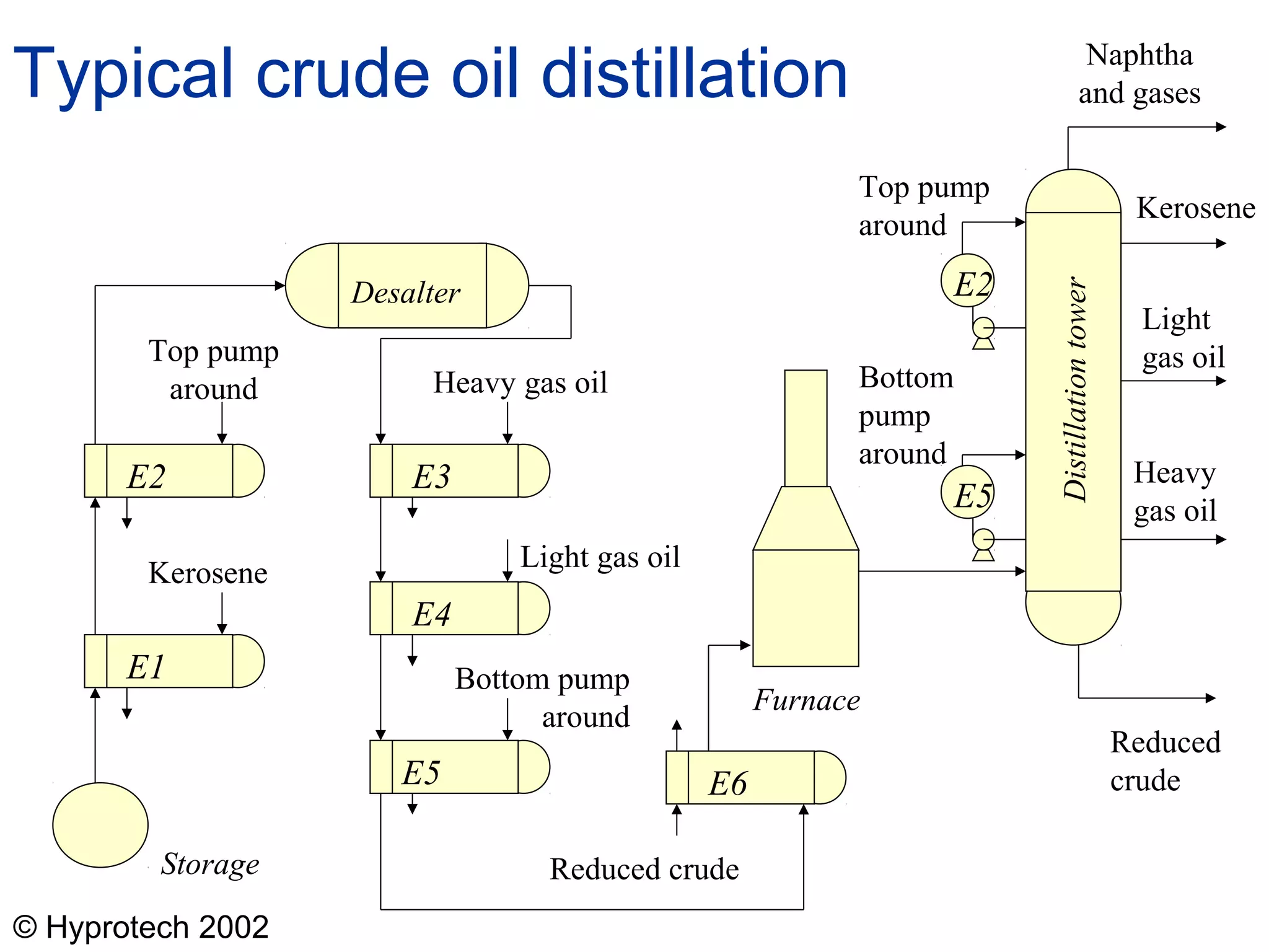
  • #10 This illustrates that real flow-sheets are much more complicated than the idealised cases shown previously. The many exchangers are to heat up streams to the required temperature for distillation. The main heat input is from the furnace or fired heater shown. Also, as much heat as possible is recovered when the refined streams are cooled down. As if this were not complicated enough, many of the exchangers shown would actually be groups of exchangers.
  • #11 There, in practice, many more heat exchangers in a real plant.
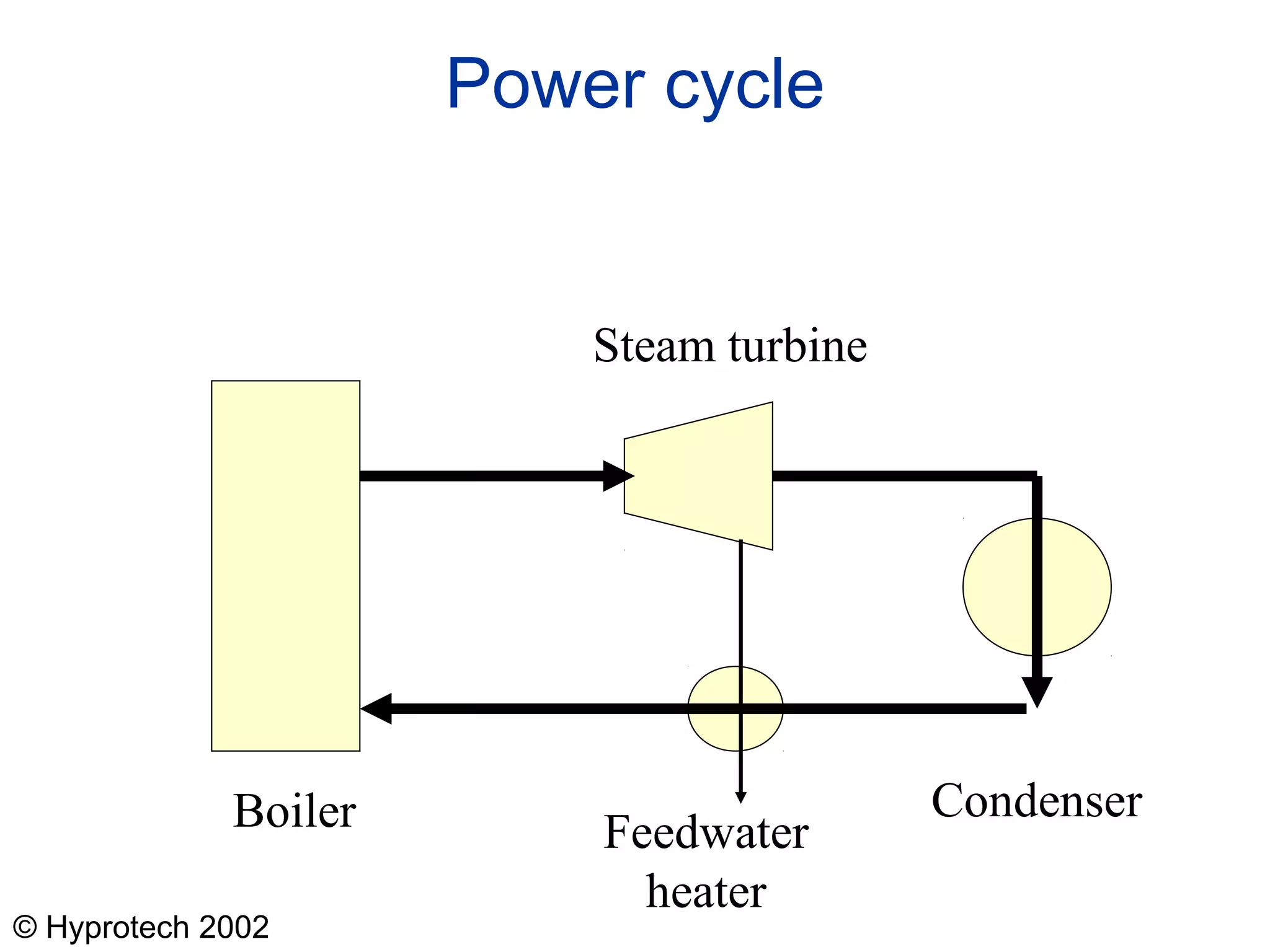
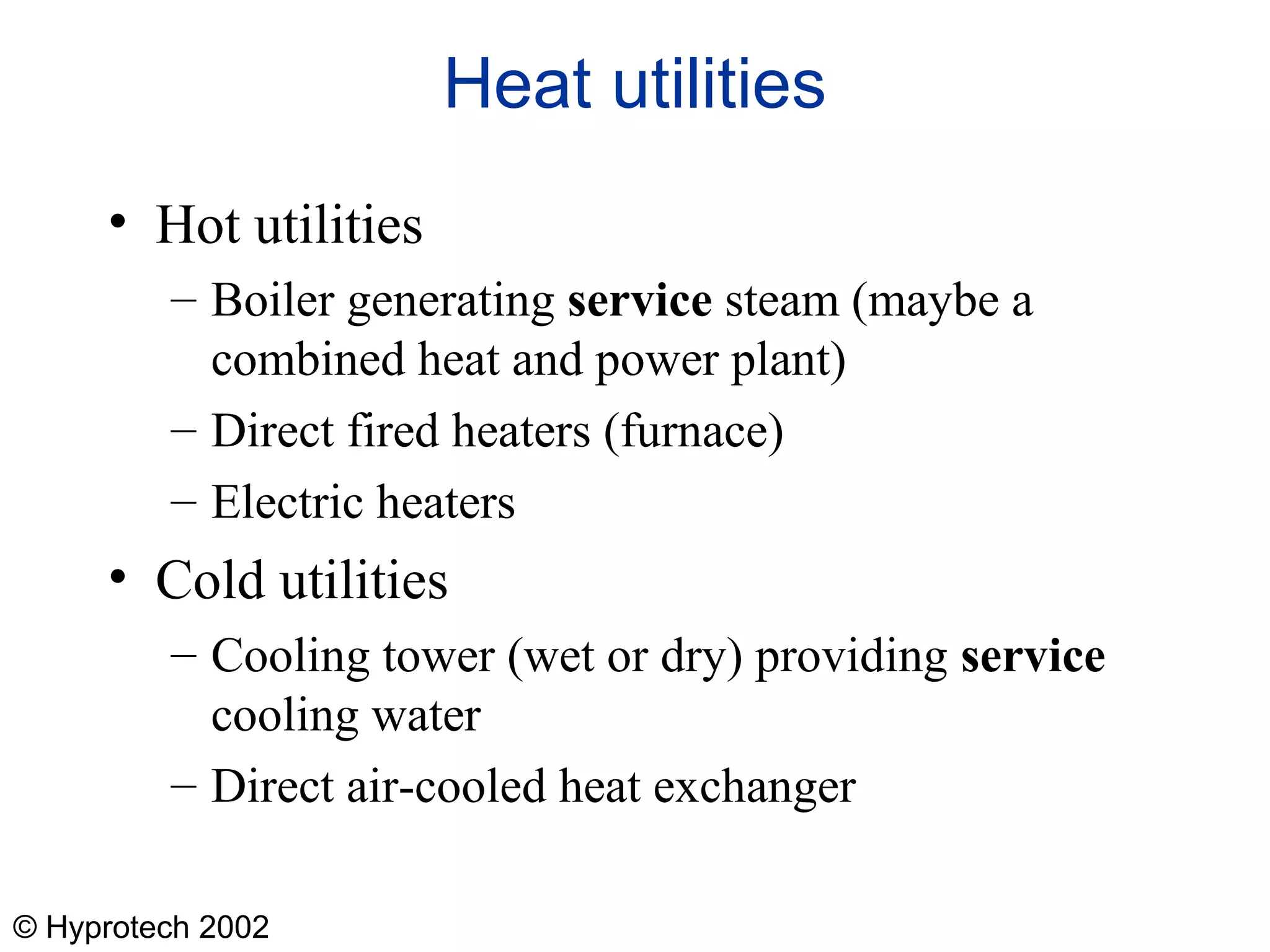
  • #13 The refinery example shown previously, the hot utility is the furnace.
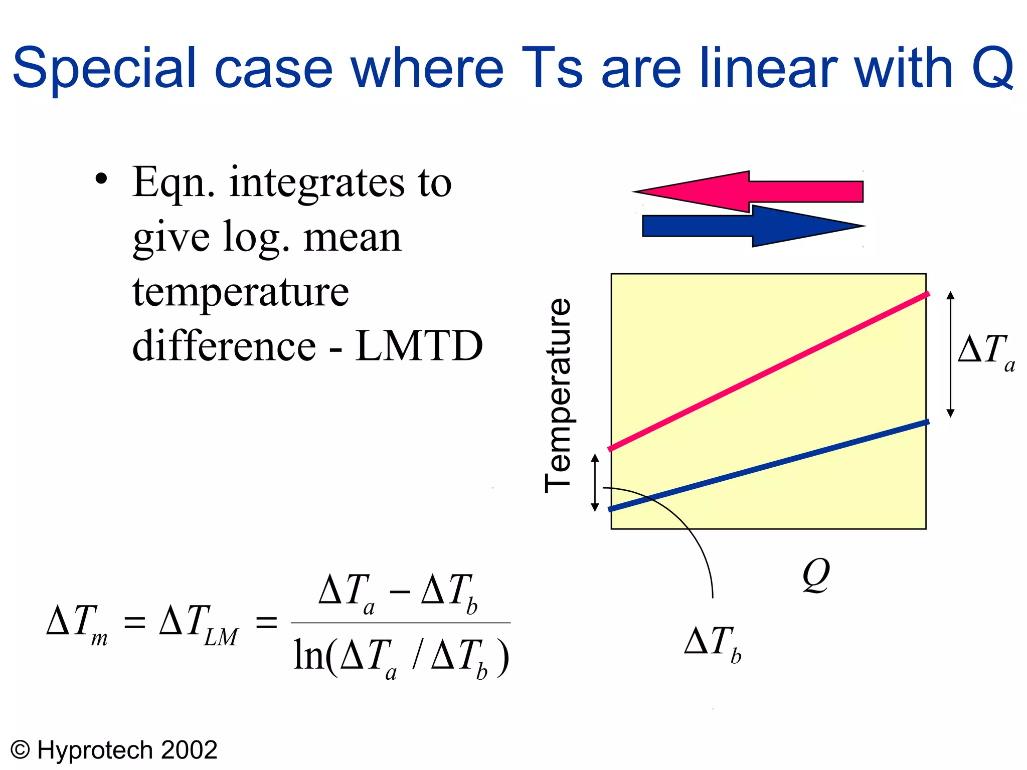
  • #18 It is worth mentioning that the log mean becomes the arithmetic mean when the two end temperature differences become the same. Students could try the derivation. The starting point is a simple change of variables. Given that T varies as a straight line with Q, the equation from the last slide may be rewritten as
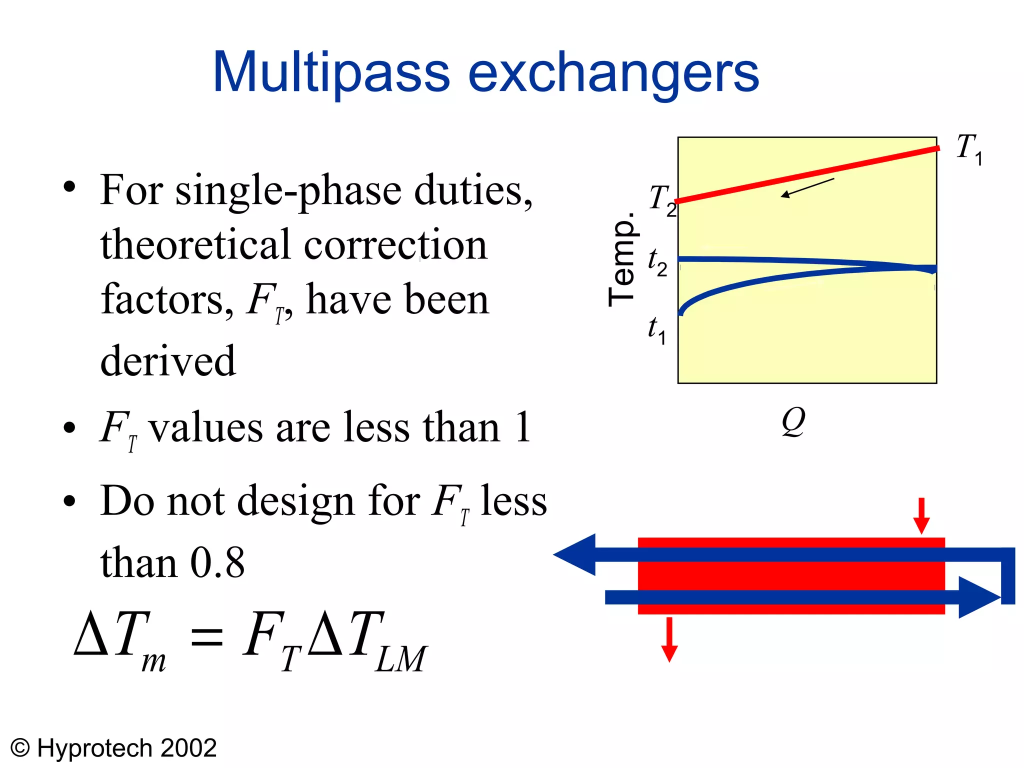
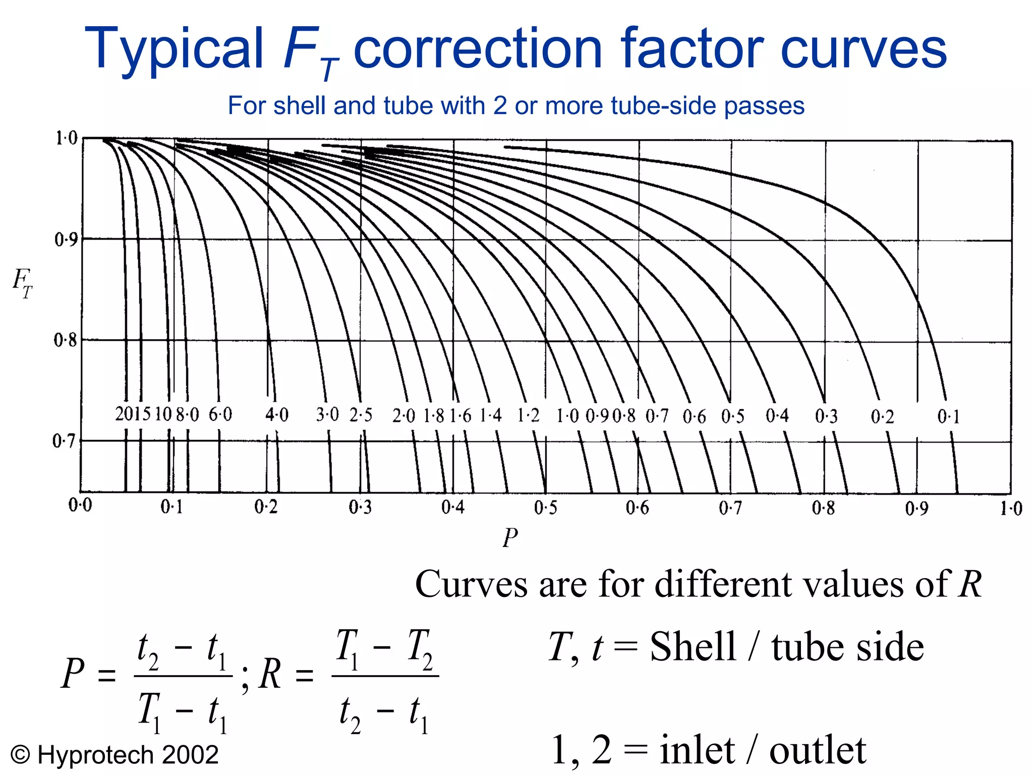
  • #19 It should be stressed that modern design software does not use these correction factors because their derivation involves too many assumptions that are not realised in practice. In stead, modern software carries out numerical intigrateions to obtain the results.
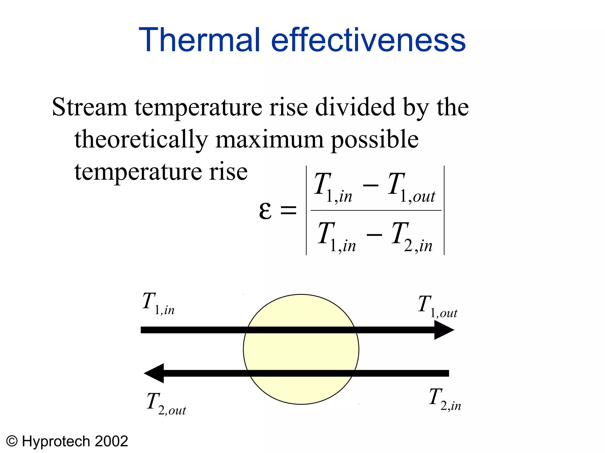
  • #21 There are two values of  depending on which stream is taken as stream 1. We are concerned with the higher of the two in this lecture series.
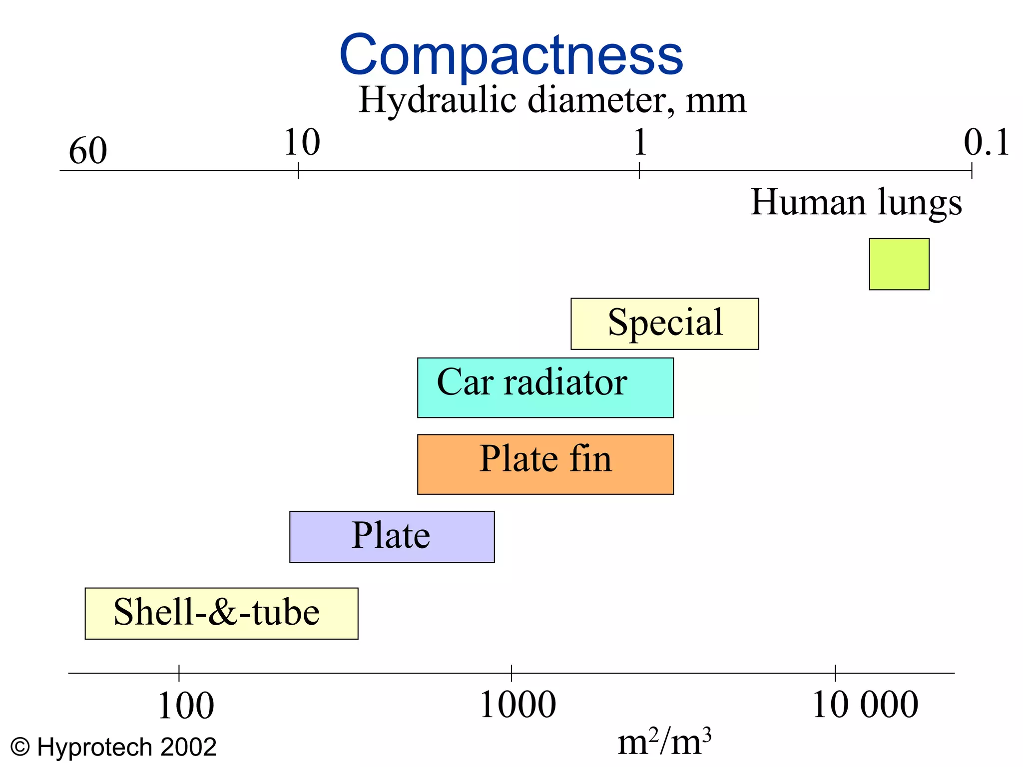
  • #23 The human lung is included to put mans designs into the context of what nature achieves. However, our lungs are mainly mass transfer devices which transfers oxygen to the blood and removes carbon dioxide. Nevertheless, the lungs have an important heat transfer function. The air we breath in is relatively cold and must be heated to blood heat before making close contact with the blood. The air is therefore heated as it is taken in, thus cooling the various passage ways through which it flows. These passage ways are reheated as we breath out the stale air. The is a form of “regenerative heat exchanger”.
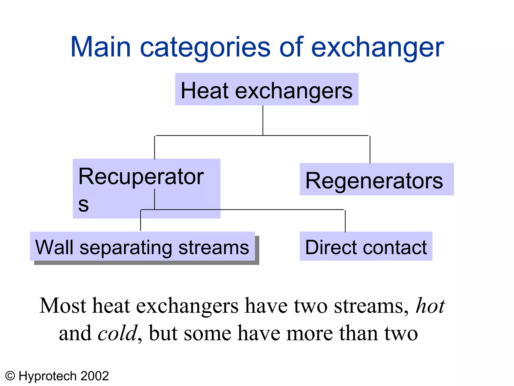
  • #24 The case of recuperators with the wall separating the streams is highlighted. It is the most important and the main subject of these lectures.
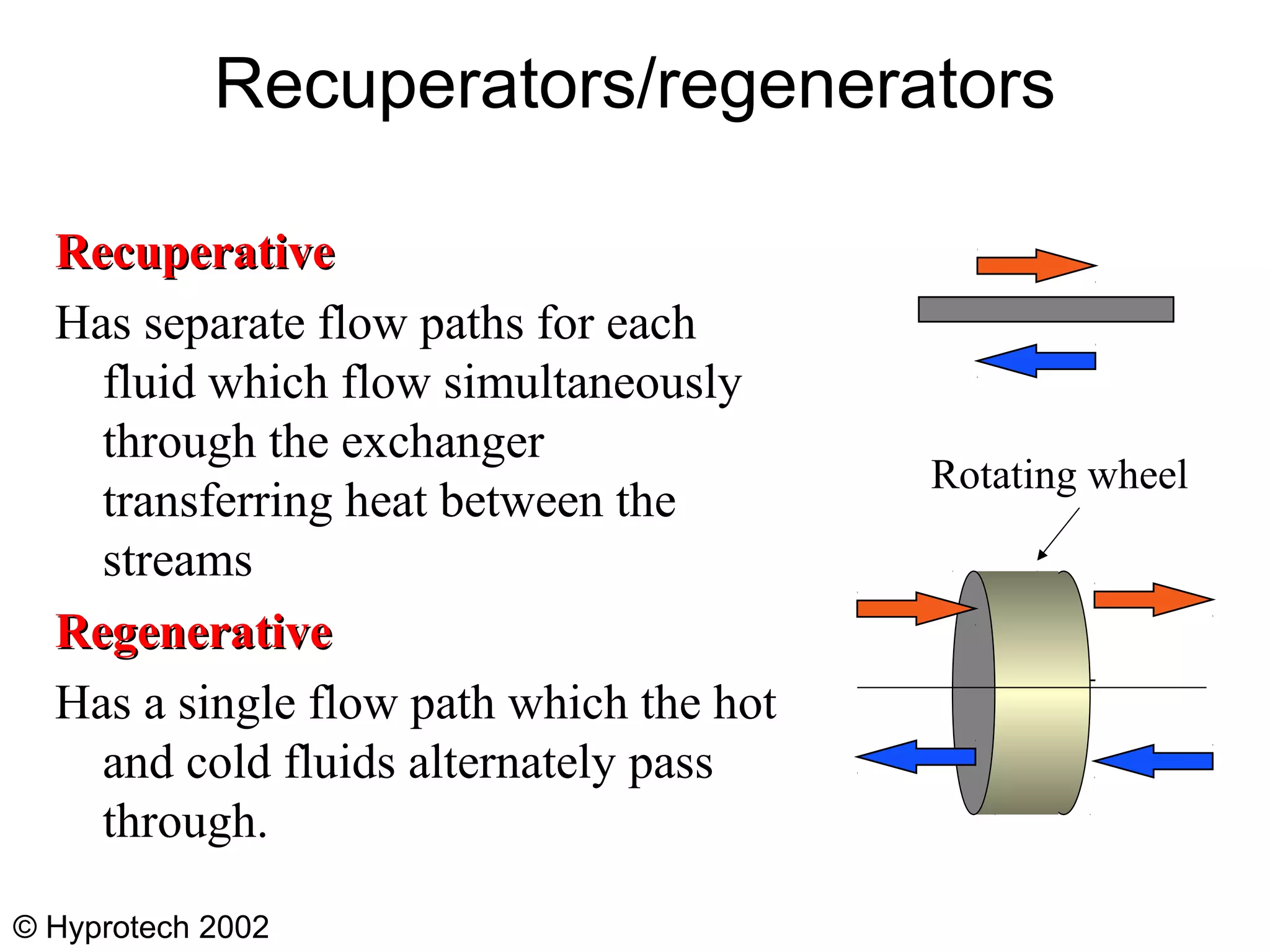
  • #25 As has been noted, the human lung acts as a regenerator because the cold stream (the incoming air) passes through the same passages as the hot stream (the outgoing stale air). The regenerator shown above is a heat wheel.
  • #32 Photograph from APV
  • #34 Forced draught most common because it is easier then to service the fan motor and also the fan motor runs cooler
  • #35 Picture from Motherwell Bridge Thermal
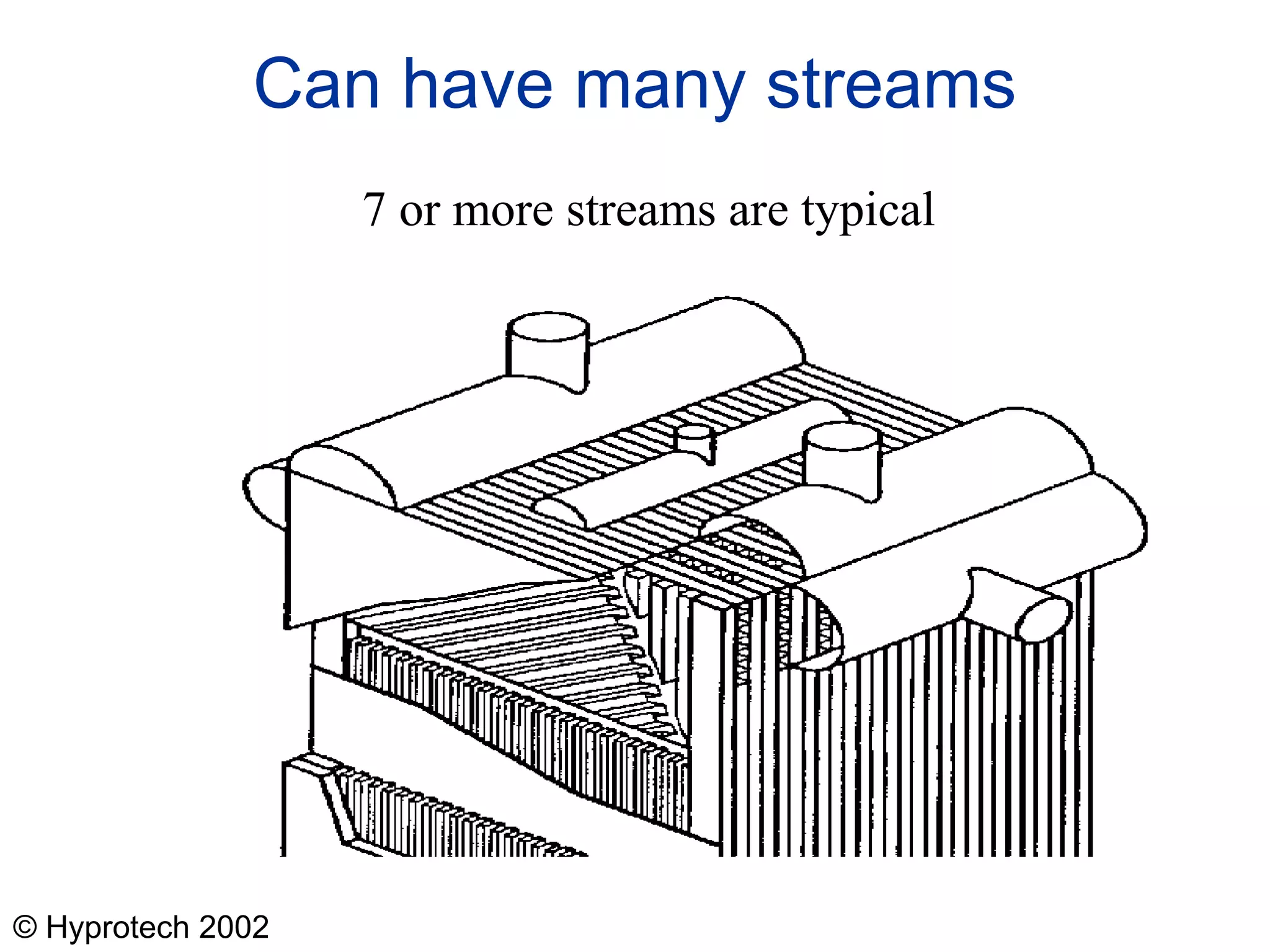
  • #37 Figure shows a number of interesting points The way headers are arranged The way gaps are left at appropriate places to allow flow between the layer and the header The use of low frequency finning to distribute the flow across the channel
  • #38 Photograph from Chart Heat Exchangers Ltd
  • #43 Photograph from Heatric Ltd
  • #44 Photograph from Heatric Ltd
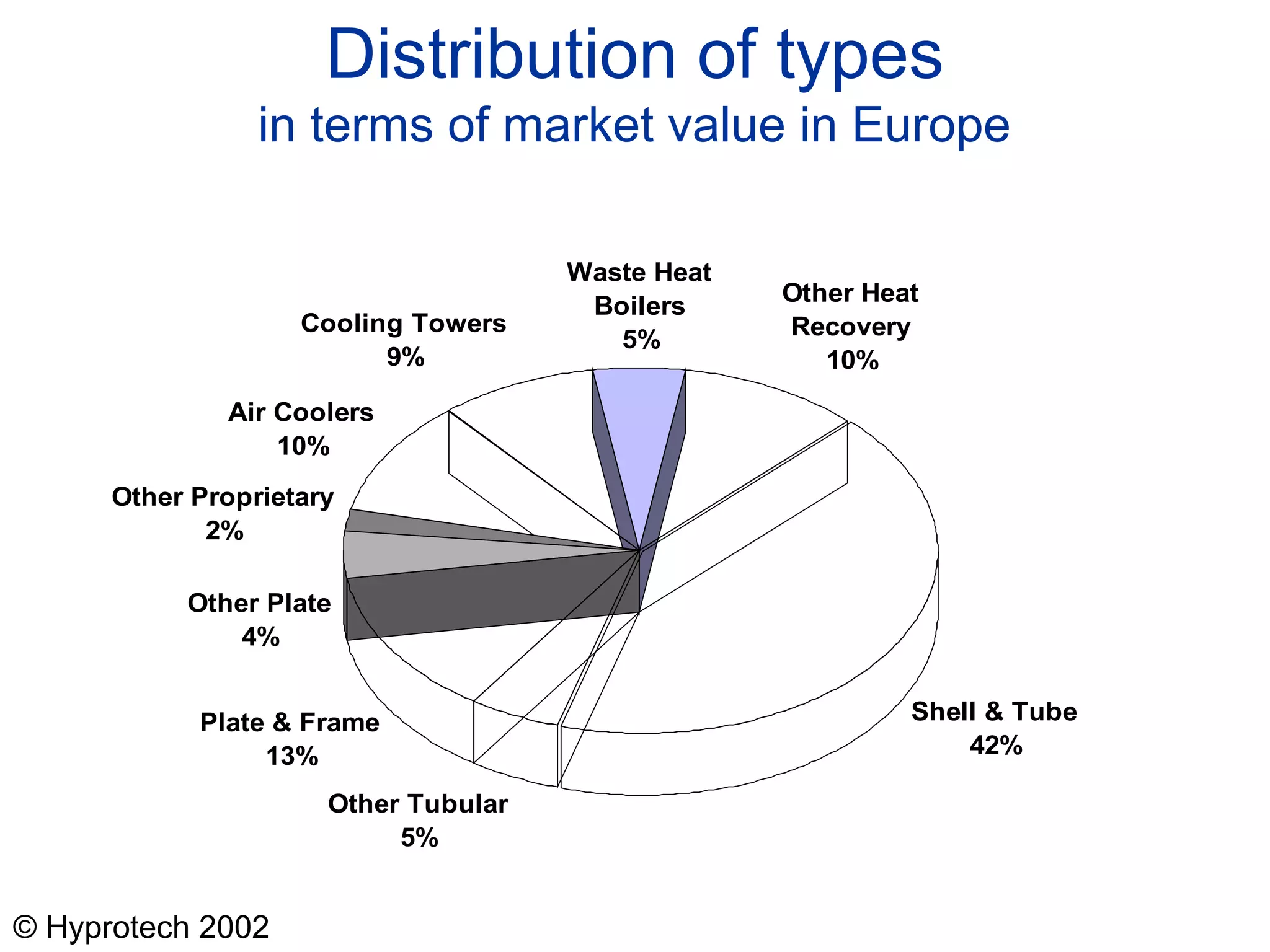
  • #45 This is for a wide range of industrial heat exchangers. If we look at chemical and refinery applications, the shell and tube type predominates (see lecture 3).