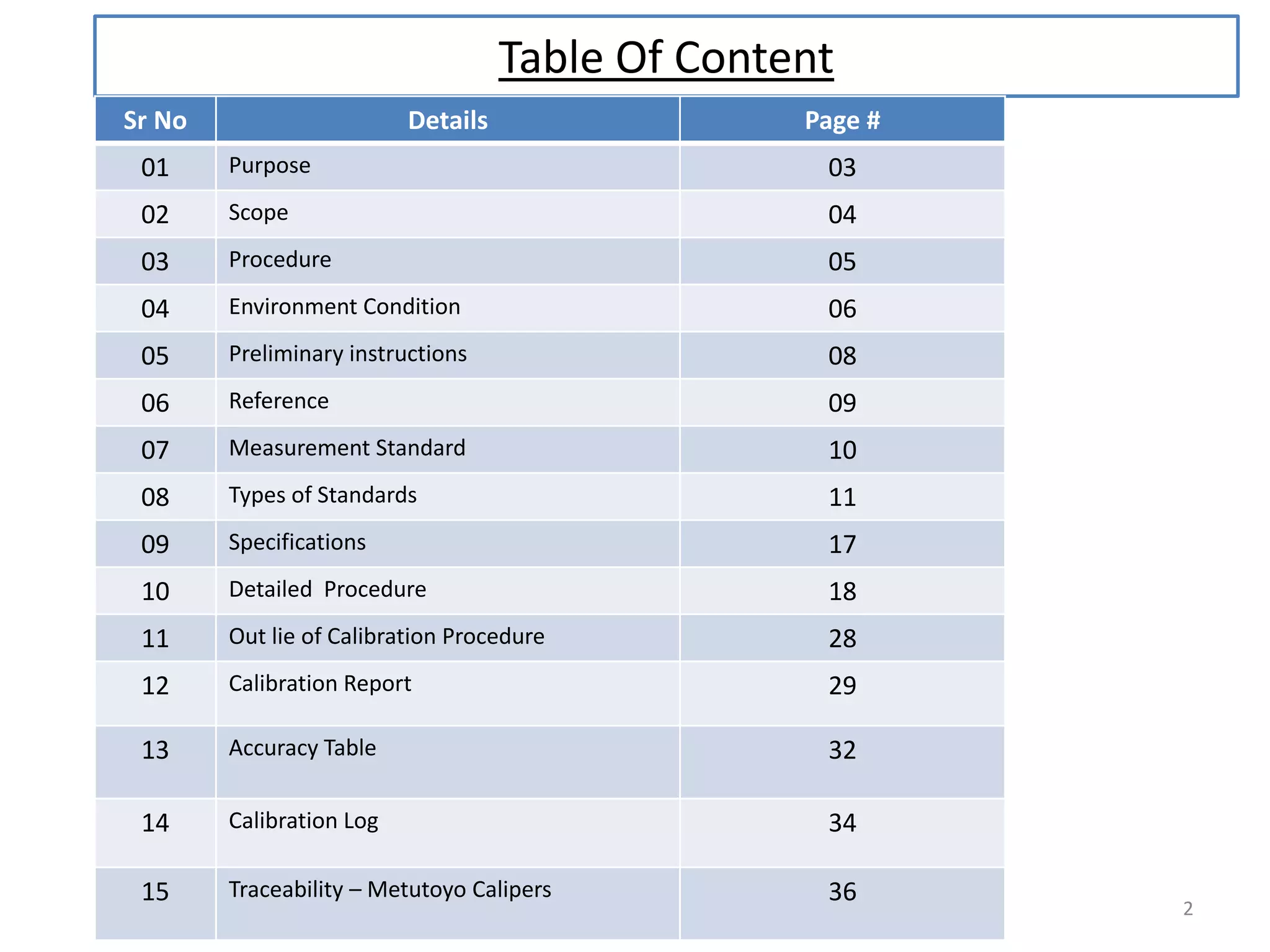
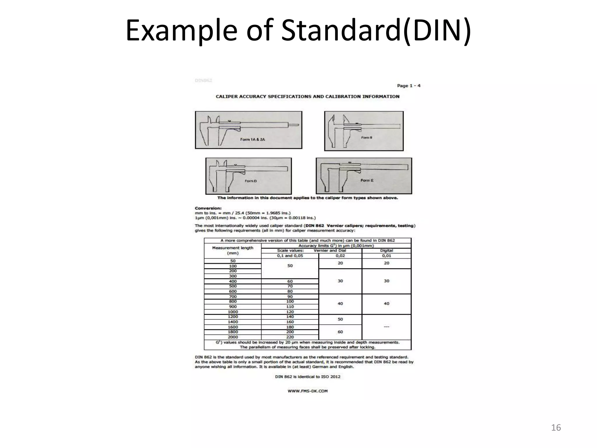
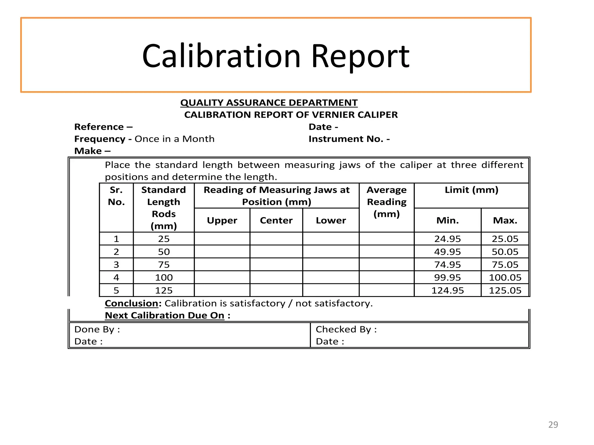
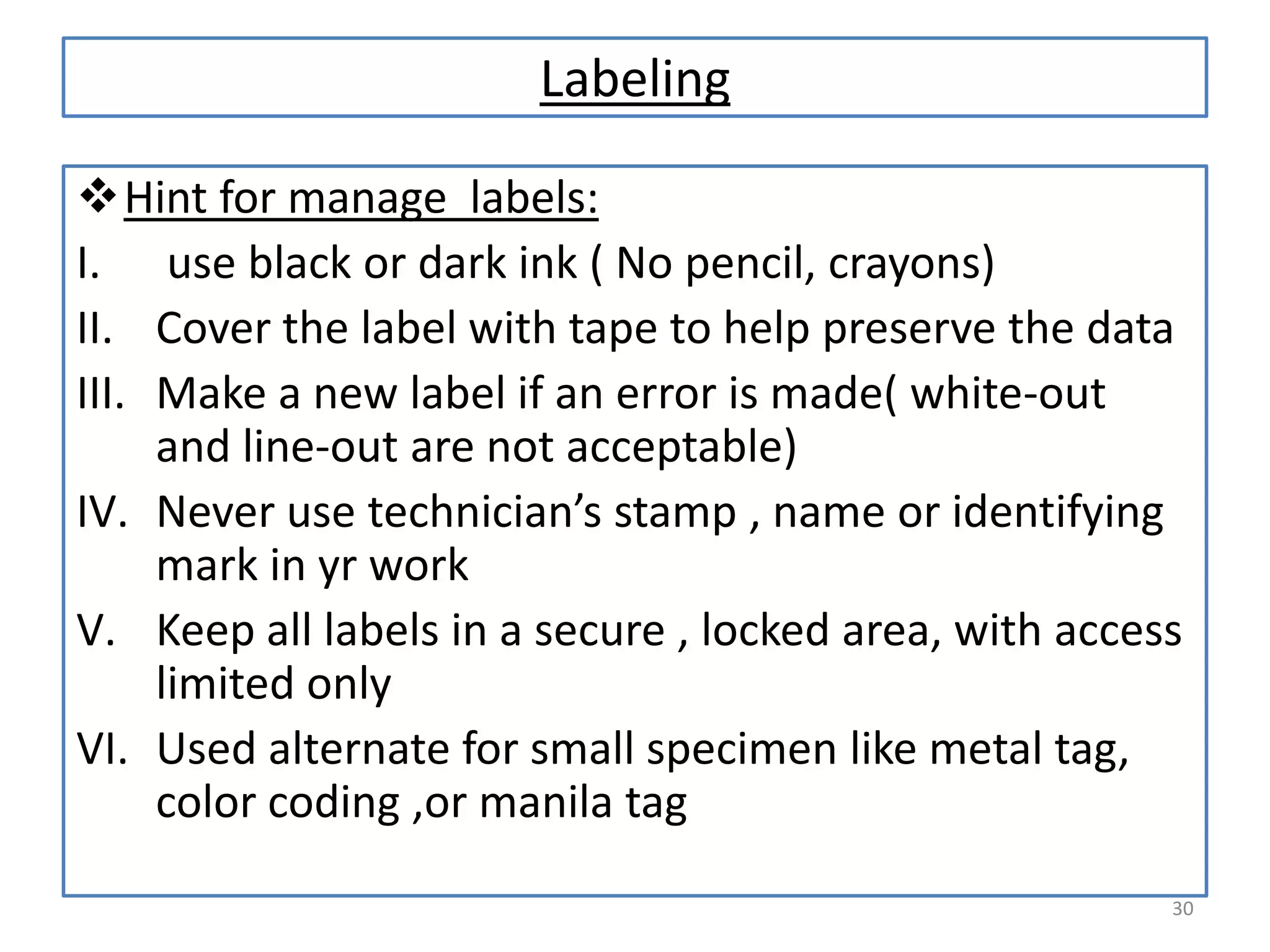
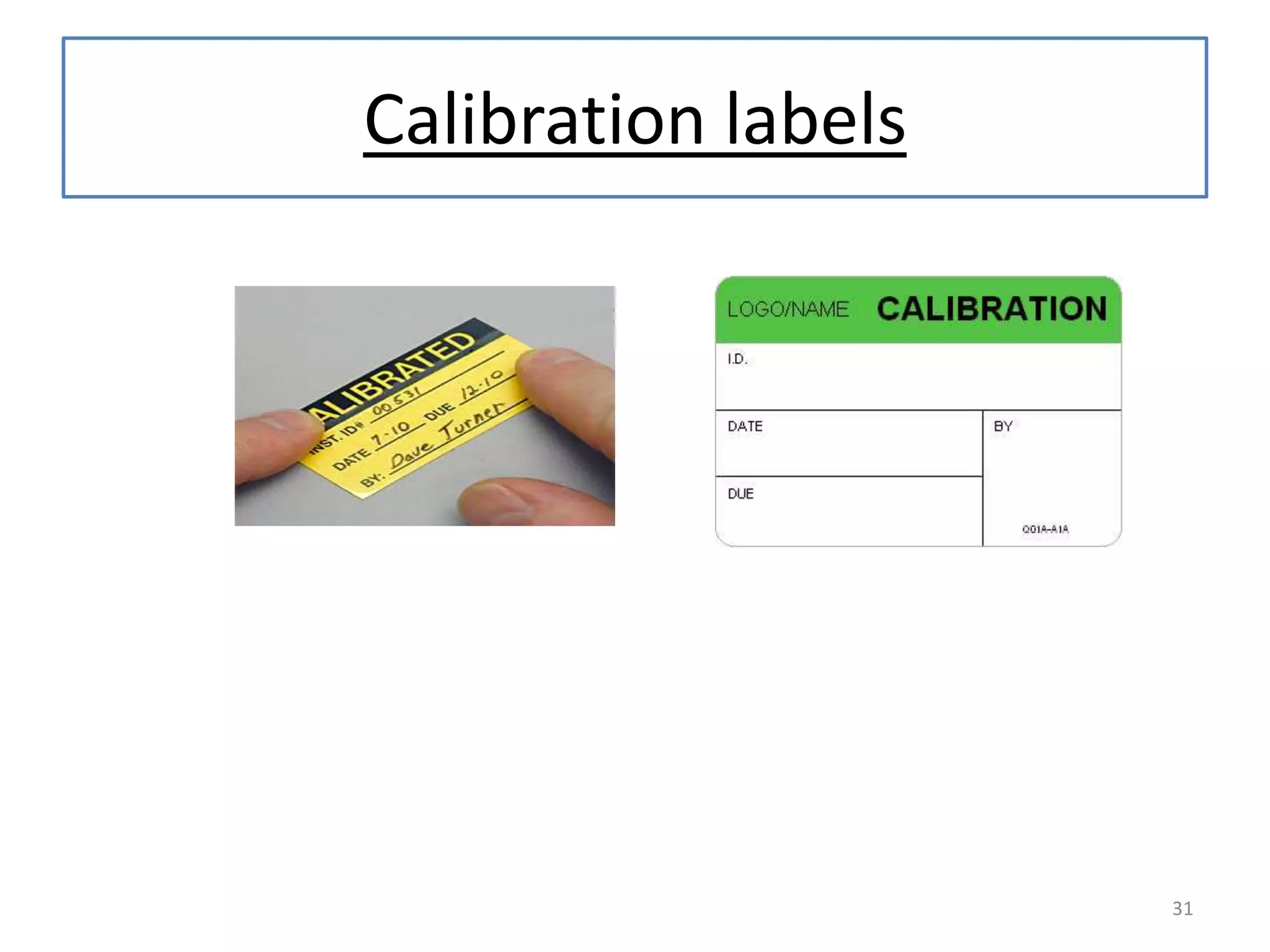
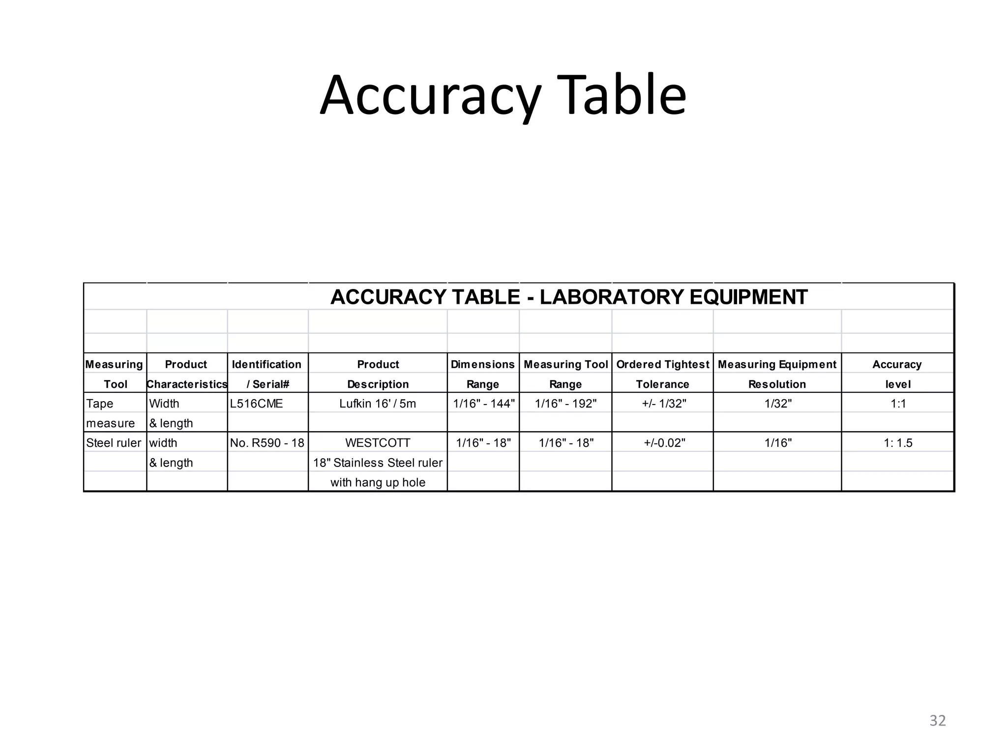
CALIPERS
CALIBRATION
By:Mukesh Jeswani

1
Table Of Content
Sr No

Details

Page #

01

Purpose

03

02

Scope

04

03

Procedure

05

04

Environment Condition

06

05

Preliminary instructions

08

06

Reference

09

07

Measurement Standard

10

08

Types of Standards

11

09

Specifications

17

10

Detailed Procedure

18

11

Out lie of Calibration Procedure

28

12

Calibration Report

29

13

Accuracy Table

32

14

Calibration Log

34

15

Traceability – Metutoyo Calipers

36

2
PURPOSE
• Provide general instruction for calibration of calipers
• Types of calipers
1. Vernier
2. Dial
3. Digital

3
Scope
• All calipers used to measure ,gage,test,inspect and
control part compliance to customer specifications
and drawings.
• Principle measuring surfaces of calipers should be
calibrated.

4
Procedure
• Priliminary Instructions and notes.
1. Calibration shall be performed in an environment
condition specified by manufactures manuals
• Impact of environment like temperature, humidity,
radio frequency ,vibration and dust control to
make accurate measurement for calibration of
calipers
• As per ISO/IEC17025 laboratory shall monitor,cotrol
and record environmental condition at the time of
calibration
5
Environment Condition
• Following things to remember for maintaining a laboratory
environment.
1. 45 % relative humidity is maximum for dimensional areas
to prevent rust
2. 20% minimum for preventing equipment from static
discharge
3. Temp must be measured at work surface height
4. Temp must be measured at several point at working
surface height.
5. Air pressure should be heigher then surrounding area to
reduce dust
6. Temp. must be 20 ± 0.3°C and humidity 20 to 45 % in
calibration laboratory
6
Environment Condition
7.The temp. control necessary depends on item which
to be calibrated and uncertainties required .
8.For controlled temperature for item which calibrated
may allow to soak in liquied.Temperature difference
between equipment,standareds and the item being
measured are as small as possible.

7
Priliminary instructions
2
3
4
5
6

The caliper will hereafter be referred to as the
instrument under test (IUT)
Verify that IUT is clean and visually examine .
Refer to manufacture manual if any of the requirement
cannot be meet for calibration of calipers.
If defect observed while calibration continue then
discontinue calibration and necessary corrective action
should be taken.
Use extreme care when removing dirt, fingerprints and
other foreign substances so that cleaning solutions do
not enter internal portions of the IUT

8
Reference
• Manufacturers Manual
• Its defined as materials whose property value are
sufficiently homogenous and well established to be
used for calibration of apparatus and assessment of
measurement method.
• Materials whose property value are traceable to
procedure that establishes traceability to accurate
realization of the unit in which property values are
expressed. It is called certified reference material
9
Measurement Standard

• It is defined as a materials measure measuring
instrument ,reference materials or measuring system
intended to define ,realize, conserve or reproduce a
unit of one or more values of a quantity to serve as a
reference.

10
Types Of Standards
1. International
• It recognized by international agreement to serve
internationally as the basis for fixing the value of all
other standard
• Example : Prototype of kilogram maintain at the
international Bureau of weight and Measures(
BIPM) is an international standard for Mass

11
Types Of Standards
2 . National
•

•

A standard recognized by an official national
decision to serve in a country as the basis for
fixing the value of all other standards of quantity
concerned. It is primary standard to which
others standard are traceable.
Example: Identical prototype of national
kilogram to prototype with international
prototype, are maintain national standard of
mass in various NMIs
12
Types Of Standards
3. Primary
• Having highest metrological quality.
• Values accepted without reference to other standard
of the same quality.
• National standard are generally primary standard.

13
Types Of Standards
4. Secondary
• Standard whose value is based on comparison with
some primary standard.
• Once its value establish then it become primary
standard for other users.
5. Reference
• Having highest metrological quality available at
given location from which the measurement made
at that location are derived.

14
Types Of Standards
6. Working:
A measurement standard not specifically reserved as
a reference standard which is intended to verify
measuring equipment of lower accuracy.
7. Transfer
Standard same as reference standard except that it
is used to transfer a measurement parameter from
one organization to another for traceability
purposes.
15
Example of Standard(DIN)

16
Specifications
•

•

•
•
1.
2.
3.
4.
5.
6.

Its determined by calipers manufacturer’s documentation.
Standards listed below should be selected on the basis of
their higher accuracy level when compared to the unit
under test.
Equivalent Standards must be equal to or better than the
minimum –use-specification.
Minimum-Use-Specification for standards listed are ¼ the
accuracy required by the IUT
Cleaning solution
Hard arkansas stone
Lint free cloth
Gage block set
Fine wire or nylon brush
Guage oil
17
Detailed Procedure
1. Carefully examine all gauging surfaces for
nicks,burrs,sratches,wear or other signs of
mishandling that may affect accuracy of the
instrument.Remove any positive imperfections
utilizing a hard arkansas stone.
2. Apply sufficient amounts of cleaning solution to
dampen a lint free cloth. Carefully clean all exposed
surfaces removing all foreign material and
particulate matter by using brush on pinion track if
neccessary.lightly apply gauge oil to clean surfaces.
18
Detailed Procedure(Conti..)
3. Check O.D jaws when in the closed position. Hold
calipers to light source and visually examine for light
between the jaws.Light will not be seen if jaws are
parallel.
4. Check I.D. Knife –edge jaws for wear when in the close
position.Caliper must be positioned squarely in line of
sight to detect air gaps or surface imperfections
between jaws.

19
Detailed Procedure(Conti..)
5. Verify zero setting of caliper by observing the
indicated reading with jaws in the closed position.If
calipers does not read 0.000,Dial caliper can be easily
adjusted to zero by loosening the bezel lock screw
,then rotating bezel to align the zero graduation to
the pointer.
6. Check depth measuring feature using gage
block.Note dial reading when checked at zero and at
the measured value of the gage block.
20
Detailed Procedure(Conti..)
7.Check depth measuring feature using gage block.Note
reading when checked at zero and at the measured
value of the gage block.
8. If any defects have been found at this point that
would affect accuracy or function of the
gage,discontinue calibration and refer for remedial
action.
9. Check four quadrants equally spaced throughout the
entire measurement range of the caliper e.g
1.000”,3.000”,4.000”,6.000”
21
Detailed Procedure(Conti..)
10.Align the beam of the caliper to be as nearly parallel to
the line of measurement as possible.
11.Tighten clamp screw on the movable jaw without
disturbing “feel” between the caliper and gage block to
ensure precision measurement.The clamp screw must
be tightened due to the “play” within the sliding
member on the movable jaw.
12.Read caliper without disturbing placement. If not
carefully remove caliper to obtain reading.

22
Detailed Procedure(Conti..)
13.Repeat the measurement steps a sufficient number of
times to rule out any obviously incorrect reading.
14. Record all above reading on the Equipment
Calibration Record.
15.Label each instrument with calibration date,
due date and person performing calibration.

23
Calibration Interval
• Calibration interval depend on how often used of
calipers ,types of environment and to what extent
the user expects it to repeat measurement
• Company is monitoring how often each calibration
performed met or did not meet specification by which
it give pass result and fail result as per specification.
• Pass rate = number of times passed calibration –
number of time failed calibration/total number of
calibration
24
Detailed Procedure(Conti..)
• If pass rate varied between 98 to 100 % then interval
were double ,95 to 98 % then interval were increased
by 50% and for below 95 % then interval should be
reduce or monitored for another round of
calibration.
• Calibration interval analysis methods are categorized
by their effectiveness ,cost to implement , their
suitability for large and small inventories and others
factors.
• Two group for analysis of calibration interval
1. Use statistical test 2. without statistical test
25
Detailed Procedure
• Next due date calculate by date, month and years
from day the equipment was last calibrated . Others
used only month and year.
• More flexible when used only day and month by
doing calibration when production shutdown for
maintenance and repair used for calibration of
equipment.
• In day/month/years system exact interval is applied
to each calipers equipment.

26
Detailed Procedure
• Subset of interval analysis is Delay Dating
• It is a practice of lengthening the calibration interval
by amount of time after calibration that equipment is
not in use and kept in storage under controlled
condition.
• Benefit for saving time and money

27
Out Line Of Calibration Procedure
PROCEDURE:
• Place the standard Lengths of 25 mm between the measuring jaws of the
caliper at three different positions and determine the length.
• Determine the average length and record the observations.
• Repeat the above procedure for the remaining standard lengths (50 mm,
75 mm, 100 mm and 125mm).
• Tolerance: + 0.05 mm
• Frequency: Once in a month
• Maintenance & repairs:
• When the instrument does not comply with the requirement specified
above; the instrument should be labelled as “Out of Calibration” and
should get repaired / serviced.
• After repairing / servicing the instrument before taking for use, the
instrument must be calibrated as per the above-mentioned procedure.

28
Calibration Report
QUALITY ASSURANCE DEPARTMENT
CALIBRATION REPORT OF VERNIER CALIPER
Reference –
Date Frequency - Once in a Month
Instrument No. Make –
Place the standard length between measuring jaws of the caliper at three different
positions and determine the length.
Sr.
Standard
Reading of Measuring Jaws at
Average
Limit (mm)
No.
Length
Position (mm)
Reading
Rods
(mm)
Upper
Center
Lower
Min.
Max.
(mm)
1
25
24.95
25.05
2
50
49.95
50.05
3
75
74.95
75.05
4
100
99.95
100.05
5
125
124.95
125.05
Conclusion: Calibration is satisfactory / not satisfactory.
Next Calibration Due On :
Done By :
Checked By :
Date :
Date :

29
Labeling
Hint for manage labels:
I. use black or dark ink ( No pencil, crayons)
II. Cover the label with tape to help preserve the data
III. Make a new label if an error is made( white-out
and line-out are not acceptable)
IV. Never use technician’s stamp , name or identifying
mark in yr work
V. Keep all labels in a secure , locked area, with access
limited only
VI. Used alternate for small specimen like metal tag,
color coding ,or manila tag
30
Calibration labels

31
Accuracy Table

ACCURACY TABLE - LABORATORY EQUIPMENT

Measuring

Product

Tool

Characteristics

Tape

Width

measure

Identification
/ Serial#

Dim ensions Measuring Tool Ordered Tightest Measuring Equipm ent

Accuracy

Description

Range

Range

Tolerance

Resolution

level

Lufkin 16' / 5m

1/16" - 144"

1/16" - 192"

+/- 1/32"

1/32"

1:1

WESTCOTT

1/16" - 18"

1/16" - 18"

+/-0.02"

1/16"

1: 1.5

& length

Steel ruler width
& length

L516CME

Product

No. R590 - 18

18" Stainless Steel ruler
with hang up hole

32
Accuracy Table Of different Calipers used at
company

Accuracy Table of diffent Calipers uesd at Company:
Inch/Metric

Part #
500-159-20*
500-160-20*
500-163-20*
500-164-20*
500-165*
500-166*
500-167
500-168
500-170-20
500-171-20
500-172-20

Range Accuracy LCD Resolution
0-6in
0-150mm
0-6in
0-150mm
0-8in
0-200mm
0-8in
0-200mm
0-12in
0-300mm
0-12in
0-300mm
0-12in
0-300mm
0-12in
0-300mm
0-4in
0-100mm
0-6in
0-150mm
0-8in

±.001in
±.001in
±.001in
±.001in
±.0015in
±.0015in
±.0015in
±.0015in
±.001in
±.001in
±.001in

.0005in
0.01mm
.0005in
0.01mm
.0005in
0.01mm
.0005in
0.01mm
.0005in
0.01mm
.0005in
0.01mm
.0005in
0.01mm
.0005in
0.01mm
.0005in
0.01mm
.0005in
0.01mm
.0005in

Remarks
Carbide-tipped jaws for OD measurement
Carbide-tipped jaws for OD and ID measurement
Carbide-tipped jaws for OD measurement
Carbide OD/ID Jaws
Carbide-tipped jaws for OD measurement
Carbide-tipped jaws for OD and ID measurement
Carbide-tipped jaws for OD measurement
Carbide-tipped jaws for OD and ID measurement
.075" Round depth bar
-

33
Calibration Log
Current
date

QA EQUIPMENT CALIBRATION LOG

Item

Equipmen
t
Identificati
Descriptio on / Serial
n
#
Location

Gram
Scale
Weight

ACCULAB Serial#
QA Lab Vicon
19356069 tabel

Digital
force
gauge

Mar-10
Corp

Model#
MG50 SN#
59908

Calibratio
n
Frequenc YR 2006 Calibrated YR 2007 Calibrated YR 2008 Calibrated YR 2009 Calibrated YR 2010 Calibrated
y
Date by
Date by
Date by
Date by
Date by

Annually

Nov/3/06

Calibrated
by
Interweigh
Systems
Inc.

Interweigh
Interweigh
Systems
Systems
4-Dec-07 Inc.
16-Mar-09 Inc.

Annually

Interweigh
Interweigh
Systems
Systems
6-Mar-09 Inc.
18-Mar-10 Inc.

18-Mar-10 In-House

20-Jun-13

Due date

18-Mar-11

18-Mar-11

Production Weight Scales

Gram
Weight
Scale
Mettler
Toledo
Weight
Scale

Serial #
Scout Pro- 71232621
SP 202
12
Lost

Serial #
Scale #1- 0016008PTHK
6DF
Reclaim

Oct/27/0
Annually 6

Oct/27/0
Annually 6

Calibrated
by
Interweigh
Systems
Inc.
Calibrated
by
Interweigh
Systems
Inc.

Lost
Interwei
gh
Systems
4-Dec-07 Inc.

Interwei
gh
Systems
3-Jun-08 Inc

Interwei
gh
Systems
1-Jun-09 Inc
########

Interwei
gh
Systems
Inc

18-Mar-11

34
35
Traceability – Metutoyo Calipers

36

Calipers presentation mukesh

  • 1.
  • 2.
    Table Of Content SrNo Details Page # 01 Purpose 03 02 Scope 04 03 Procedure 05 04 Environment Condition 06 05 Preliminary instructions 08 06 Reference 09 07 Measurement Standard 10 08 Types of Standards 11 09 Specifications 17 10 Detailed Procedure 18 11 Out lie of Calibration Procedure 28 12 Calibration Report 29 13 Accuracy Table 32 14 Calibration Log 34 15 Traceability – Metutoyo Calipers 36 2
  • 3.
    PURPOSE • Provide generalinstruction for calibration of calipers • Types of calipers 1. Vernier 2. Dial 3. Digital 3
  • 4.
    Scope • All calipersused to measure ,gage,test,inspect and control part compliance to customer specifications and drawings. • Principle measuring surfaces of calipers should be calibrated. 4
  • 5.
    Procedure • Priliminary Instructionsand notes. 1. Calibration shall be performed in an environment condition specified by manufactures manuals • Impact of environment like temperature, humidity, radio frequency ,vibration and dust control to make accurate measurement for calibration of calipers • As per ISO/IEC17025 laboratory shall monitor,cotrol and record environmental condition at the time of calibration 5
  • 6.
    Environment Condition • Followingthings to remember for maintaining a laboratory environment. 1. 45 % relative humidity is maximum for dimensional areas to prevent rust 2. 20% minimum for preventing equipment from static discharge 3. Temp must be measured at work surface height 4. Temp must be measured at several point at working surface height. 5. Air pressure should be heigher then surrounding area to reduce dust 6. Temp. must be 20 ± 0.3°C and humidity 20 to 45 % in calibration laboratory 6
  • 7.
    Environment Condition 7.The temp.control necessary depends on item which to be calibrated and uncertainties required . 8.For controlled temperature for item which calibrated may allow to soak in liquied.Temperature difference between equipment,standareds and the item being measured are as small as possible. 7
  • 8.
    Priliminary instructions 2 3 4 5 6 The caliperwill hereafter be referred to as the instrument under test (IUT) Verify that IUT is clean and visually examine . Refer to manufacture manual if any of the requirement cannot be meet for calibration of calipers. If defect observed while calibration continue then discontinue calibration and necessary corrective action should be taken. Use extreme care when removing dirt, fingerprints and other foreign substances so that cleaning solutions do not enter internal portions of the IUT 8
  • 9.
    Reference • Manufacturers Manual •Its defined as materials whose property value are sufficiently homogenous and well established to be used for calibration of apparatus and assessment of measurement method. • Materials whose property value are traceable to procedure that establishes traceability to accurate realization of the unit in which property values are expressed. It is called certified reference material 9
  • 10.
    Measurement Standard • Itis defined as a materials measure measuring instrument ,reference materials or measuring system intended to define ,realize, conserve or reproduce a unit of one or more values of a quantity to serve as a reference. 10
  • 11.
    Types Of Standards 1.International • It recognized by international agreement to serve internationally as the basis for fixing the value of all other standard • Example : Prototype of kilogram maintain at the international Bureau of weight and Measures( BIPM) is an international standard for Mass 11
  • 12.
    Types Of Standards 2. National • • A standard recognized by an official national decision to serve in a country as the basis for fixing the value of all other standards of quantity concerned. It is primary standard to which others standard are traceable. Example: Identical prototype of national kilogram to prototype with international prototype, are maintain national standard of mass in various NMIs 12
  • 13.
    Types Of Standards 3.Primary • Having highest metrological quality. • Values accepted without reference to other standard of the same quality. • National standard are generally primary standard. 13
  • 14.
    Types Of Standards 4.Secondary • Standard whose value is based on comparison with some primary standard. • Once its value establish then it become primary standard for other users. 5. Reference • Having highest metrological quality available at given location from which the measurement made at that location are derived. 14
  • 15.
    Types Of Standards 6.Working: A measurement standard not specifically reserved as a reference standard which is intended to verify measuring equipment of lower accuracy. 7. Transfer Standard same as reference standard except that it is used to transfer a measurement parameter from one organization to another for traceability purposes. 15
  • 16.
  • 17.
    Specifications • • • • 1. 2. 3. 4. 5. 6. Its determined bycalipers manufacturer’s documentation. Standards listed below should be selected on the basis of their higher accuracy level when compared to the unit under test. Equivalent Standards must be equal to or better than the minimum –use-specification. Minimum-Use-Specification for standards listed are ¼ the accuracy required by the IUT Cleaning solution Hard arkansas stone Lint free cloth Gage block set Fine wire or nylon brush Guage oil 17
  • 18.
    Detailed Procedure 1. Carefullyexamine all gauging surfaces for nicks,burrs,sratches,wear or other signs of mishandling that may affect accuracy of the instrument.Remove any positive imperfections utilizing a hard arkansas stone. 2. Apply sufficient amounts of cleaning solution to dampen a lint free cloth. Carefully clean all exposed surfaces removing all foreign material and particulate matter by using brush on pinion track if neccessary.lightly apply gauge oil to clean surfaces. 18
  • 19.
    Detailed Procedure(Conti..) 3. CheckO.D jaws when in the closed position. Hold calipers to light source and visually examine for light between the jaws.Light will not be seen if jaws are parallel. 4. Check I.D. Knife –edge jaws for wear when in the close position.Caliper must be positioned squarely in line of sight to detect air gaps or surface imperfections between jaws. 19
  • 20.
    Detailed Procedure(Conti..) 5. Verifyzero setting of caliper by observing the indicated reading with jaws in the closed position.If calipers does not read 0.000,Dial caliper can be easily adjusted to zero by loosening the bezel lock screw ,then rotating bezel to align the zero graduation to the pointer. 6. Check depth measuring feature using gage block.Note dial reading when checked at zero and at the measured value of the gage block. 20
  • 21.
    Detailed Procedure(Conti..) 7.Check depthmeasuring feature using gage block.Note reading when checked at zero and at the measured value of the gage block. 8. If any defects have been found at this point that would affect accuracy or function of the gage,discontinue calibration and refer for remedial action. 9. Check four quadrants equally spaced throughout the entire measurement range of the caliper e.g 1.000”,3.000”,4.000”,6.000” 21
  • 22.
    Detailed Procedure(Conti..) 10.Align thebeam of the caliper to be as nearly parallel to the line of measurement as possible. 11.Tighten clamp screw on the movable jaw without disturbing “feel” between the caliper and gage block to ensure precision measurement.The clamp screw must be tightened due to the “play” within the sliding member on the movable jaw. 12.Read caliper without disturbing placement. If not carefully remove caliper to obtain reading. 22
  • 23.
    Detailed Procedure(Conti..) 13.Repeat themeasurement steps a sufficient number of times to rule out any obviously incorrect reading. 14. Record all above reading on the Equipment Calibration Record. 15.Label each instrument with calibration date, due date and person performing calibration. 23
  • 24.
    Calibration Interval • Calibrationinterval depend on how often used of calipers ,types of environment and to what extent the user expects it to repeat measurement • Company is monitoring how often each calibration performed met or did not meet specification by which it give pass result and fail result as per specification. • Pass rate = number of times passed calibration – number of time failed calibration/total number of calibration 24
  • 25.
    Detailed Procedure(Conti..) • Ifpass rate varied between 98 to 100 % then interval were double ,95 to 98 % then interval were increased by 50% and for below 95 % then interval should be reduce or monitored for another round of calibration. • Calibration interval analysis methods are categorized by their effectiveness ,cost to implement , their suitability for large and small inventories and others factors. • Two group for analysis of calibration interval 1. Use statistical test 2. without statistical test 25
  • 26.
    Detailed Procedure • Nextdue date calculate by date, month and years from day the equipment was last calibrated . Others used only month and year. • More flexible when used only day and month by doing calibration when production shutdown for maintenance and repair used for calibration of equipment. • In day/month/years system exact interval is applied to each calipers equipment. 26
  • 27.
    Detailed Procedure • Subsetof interval analysis is Delay Dating • It is a practice of lengthening the calibration interval by amount of time after calibration that equipment is not in use and kept in storage under controlled condition. • Benefit for saving time and money 27
  • 28.
    Out Line OfCalibration Procedure PROCEDURE: • Place the standard Lengths of 25 mm between the measuring jaws of the caliper at three different positions and determine the length. • Determine the average length and record the observations. • Repeat the above procedure for the remaining standard lengths (50 mm, 75 mm, 100 mm and 125mm). • Tolerance: + 0.05 mm • Frequency: Once in a month • Maintenance & repairs: • When the instrument does not comply with the requirement specified above; the instrument should be labelled as “Out of Calibration” and should get repaired / serviced. • After repairing / servicing the instrument before taking for use, the instrument must be calibrated as per the above-mentioned procedure. 28
  • 29.
    Calibration Report QUALITY ASSURANCEDEPARTMENT CALIBRATION REPORT OF VERNIER CALIPER Reference – Date Frequency - Once in a Month Instrument No. Make – Place the standard length between measuring jaws of the caliper at three different positions and determine the length. Sr. Standard Reading of Measuring Jaws at Average Limit (mm) No. Length Position (mm) Reading Rods (mm) Upper Center Lower Min. Max. (mm) 1 25 24.95 25.05 2 50 49.95 50.05 3 75 74.95 75.05 4 100 99.95 100.05 5 125 124.95 125.05 Conclusion: Calibration is satisfactory / not satisfactory. Next Calibration Due On : Done By : Checked By : Date : Date : 29
  • 30.
    Labeling Hint for managelabels: I. use black or dark ink ( No pencil, crayons) II. Cover the label with tape to help preserve the data III. Make a new label if an error is made( white-out and line-out are not acceptable) IV. Never use technician’s stamp , name or identifying mark in yr work V. Keep all labels in a secure , locked area, with access limited only VI. Used alternate for small specimen like metal tag, color coding ,or manila tag 30
  • 31.
  • 32.
    Accuracy Table ACCURACY TABLE- LABORATORY EQUIPMENT Measuring Product Tool Characteristics Tape Width measure Identification / Serial# Dim ensions Measuring Tool Ordered Tightest Measuring Equipm ent Accuracy Description Range Range Tolerance Resolution level Lufkin 16' / 5m 1/16" - 144" 1/16" - 192" +/- 1/32" 1/32" 1:1 WESTCOTT 1/16" - 18" 1/16" - 18" +/-0.02" 1/16" 1: 1.5 & length Steel ruler width & length L516CME Product No. R590 - 18 18" Stainless Steel ruler with hang up hole 32
  • 33.
    Accuracy Table Ofdifferent Calipers used at company Accuracy Table of diffent Calipers uesd at Company: Inch/Metric Part # 500-159-20* 500-160-20* 500-163-20* 500-164-20* 500-165* 500-166* 500-167 500-168 500-170-20 500-171-20 500-172-20 Range Accuracy LCD Resolution 0-6in 0-150mm 0-6in 0-150mm 0-8in 0-200mm 0-8in 0-200mm 0-12in 0-300mm 0-12in 0-300mm 0-12in 0-300mm 0-12in 0-300mm 0-4in 0-100mm 0-6in 0-150mm 0-8in ±.001in ±.001in ±.001in ±.001in ±.0015in ±.0015in ±.0015in ±.0015in ±.001in ±.001in ±.001in .0005in 0.01mm .0005in 0.01mm .0005in 0.01mm .0005in 0.01mm .0005in 0.01mm .0005in 0.01mm .0005in 0.01mm .0005in 0.01mm .0005in 0.01mm .0005in 0.01mm .0005in Remarks Carbide-tipped jaws for OD measurement Carbide-tipped jaws for OD and ID measurement Carbide-tipped jaws for OD measurement Carbide OD/ID Jaws Carbide-tipped jaws for OD measurement Carbide-tipped jaws for OD and ID measurement Carbide-tipped jaws for OD measurement Carbide-tipped jaws for OD and ID measurement .075" Round depth bar - 33
  • 34.
    Calibration Log Current date QA EQUIPMENTCALIBRATION LOG Item Equipmen t Identificati Descriptio on / Serial n # Location Gram Scale Weight ACCULAB Serial# QA Lab Vicon 19356069 tabel Digital force gauge Mar-10 Corp Model# MG50 SN# 59908 Calibratio n Frequenc YR 2006 Calibrated YR 2007 Calibrated YR 2008 Calibrated YR 2009 Calibrated YR 2010 Calibrated y Date by Date by Date by Date by Date by Annually Nov/3/06 Calibrated by Interweigh Systems Inc. Interweigh Interweigh Systems Systems 4-Dec-07 Inc. 16-Mar-09 Inc. Annually Interweigh Interweigh Systems Systems 6-Mar-09 Inc. 18-Mar-10 Inc. 18-Mar-10 In-House 20-Jun-13 Due date 18-Mar-11 18-Mar-11 Production Weight Scales Gram Weight Scale Mettler Toledo Weight Scale Serial # Scout Pro- 71232621 SP 202 12 Lost Serial # Scale #1- 0016008PTHK 6DF Reclaim Oct/27/0 Annually 6 Oct/27/0 Annually 6 Calibrated by Interweigh Systems Inc. Calibrated by Interweigh Systems Inc. Lost Interwei gh Systems 4-Dec-07 Inc. Interwei gh Systems 3-Jun-08 Inc Interwei gh Systems 1-Jun-09 Inc ######## Interwei gh Systems Inc 18-Mar-11 34
  • 35.
  • 36.