This document provides a training module on rotary absolute encoders, specifically the AMT203 absolute encoder produced by CUI Inc. It describes the functional theory of encoders, the benefits of absolute encoders over incremental encoders, and the key components and features of the AMT203 including its capacitive sensing technology, flexible shaft and mounting options, serial interface, and purchasing options. The training objectives are to familiarize the reader with encoder technology and highlight the capabilities and advantages of CUI's AMT203 absolute encoder.
In this document
Powered by AI
Introduction to CUI's AMT203 Absolute Encoder training, covering objectives and benefits.
Overview of encoders functionality, types, rotational directions, position, speed, distance calculations, and absolute vs incremental encoders.
Applications of encoders across various industries, and types such as mechanical, optical, magnetic, capacitive.
Features of AMT203 including high resolution, broad temperature range, low current consumption, and flexible mounting options.
Details on the easy assembly and installation process, versatile mounting options, and shaft adaptations of the AMT203.
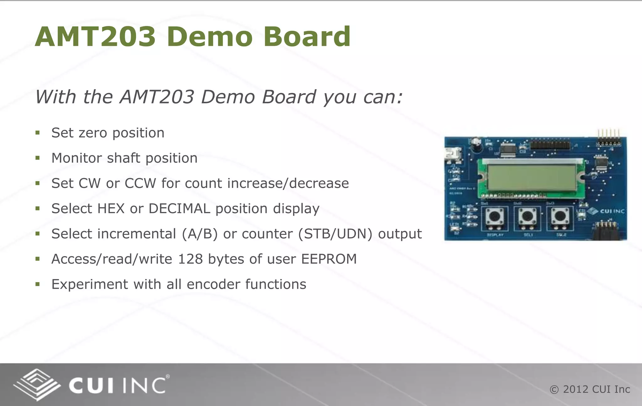
Utilization of AMT203 demo board for setting zero position and monitoring functions, including serial peripheral interface advantages.
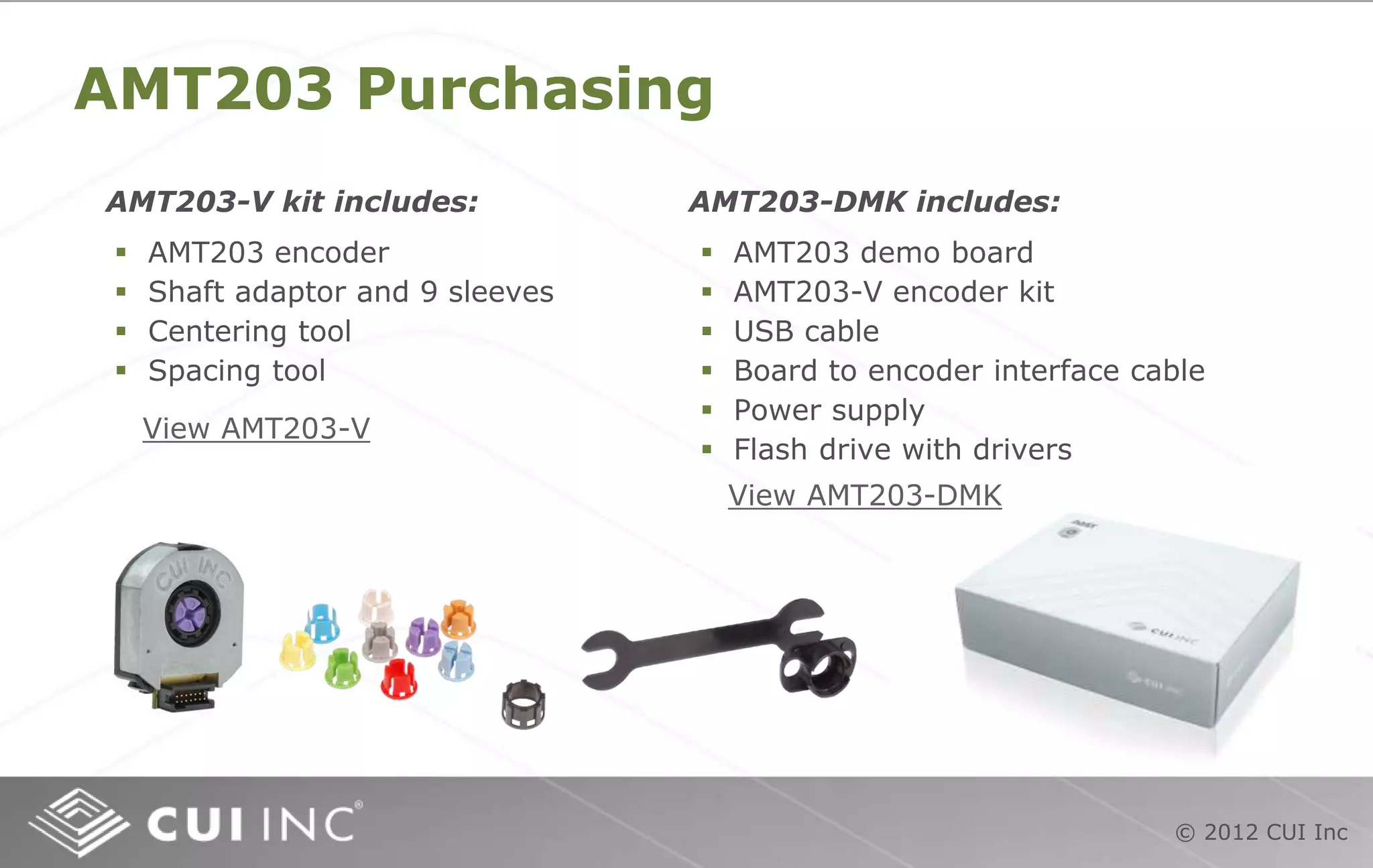
Details on purchasing the AMT203 encoder and associated kits, along with available resources.
#3 Welcome to the CUI Inc training module for the AMT203 absolute encoder. This module will discuss how encoders function, what makes the AMT203 unique and the various parts that make up this revolutionary modular encoder.
#4 An encoder is a device that senses mechanical motion. It translates motion such as speed, direction, and shaft angle into electrical signals. There are many different shapes and kinds of encoders. Most encoders generate square waves, making them ideal for use in digital circuits. For this training module we will consider only rotary encoders although encoders are also available in linear configurations.
#5 Inside an encoder there is a disc fixed to a shaft that is free to rotate. On one side of the disc is signal source, on the other side a receiver. As the disc turns, the signal source is alternately allowed to pass and be blocked. When the signal is passed through the disc, an output pulse is generated.
In the illustration, the signal transmitted in Channel A passes through the disc generating an output pulse. At the same time the signal transmitted in Channel B is blocked and no output pulse is generated. The dotted line represents the position of the disc relative to the output pulses.
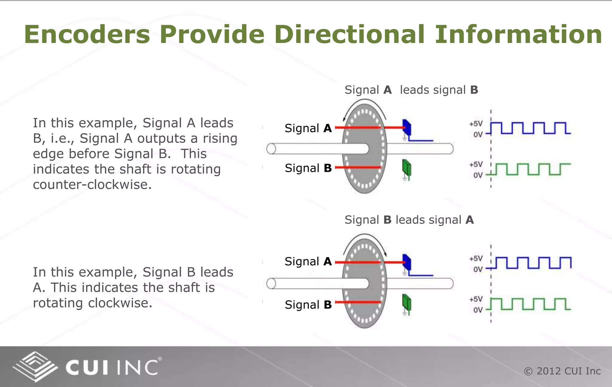
#6 Detection of shaft direction is very useful and even critical to some applications. In a radio, the rotational direction of the volume knob tells the receiving circuit whether to increase or decrease the volume with each square wave. In automation equipment, the rotational direction is detected and other operations are initiated when a pre-set number of pulses for that direction has been achieved. An elaborate and sophisticated set of movements can be executed automatically to perform tasks like placing components on a pc board, welding seams in an automobile body, moving the flaps of a jumbo jet or just about anything that involves a set of precise motions. In the first illustration above, signal A leads B, i.e., signal A outputs a rising edge before signal B. This indicates the shaft is rotating counter-clockwise. In the second illustration, signal B leads A. This indicates the shaft is rotating clockwise.
information can be obtained.
#7 Each pulse from Channel A or B increases the counter in a user’s system by one when the encoder is turning counter-clockwise and reduces by one for each pulse from the encoder when it is turning clockwise. The pulse count can be converted into distance based on the relationship between the shaft the encoder is coupled to and the mechanics that convert rotary encoder motion to linear travel.
The index channel pulse occurs only once per revolution. Often the index channel is used to initialize the position of the shaft the encoder is attached to. A motor turns the encoder until the index channel is detected as a zero or starting point and an automated process can begin. The number of complete revolutions the encoder shaft has moved can be read and recorded. The counter adds one revolution when the index occurs during counter-clockwise rotation and subtracts one turn when it occurs during clockwise rotation. By adding the turns count to the pulse count, complete and accurate rotation information can be maintained as long as the encoder is powered.
#8 Encoders can detect speed when output pulses are counted in a specified time span. The time element is typically provided by an oscillator or clock in a microcontroller. The number of pulses in one revolution must also be known. In the equation above, S represents speed, C represents the number of pulses counted, PPR the resolution of the encoder, and t represents the time interval in seconds during which the pulses were counted. The second equation shows that if 60 pulses are counted in a time interval of 10 seconds using a 360 CPR encoder, the shaft speed is 1 RPM.
#9 Encoders can detect distance traveled based on the number of pulses counted. In most applications, rotary motion is converted to linear travel by mechanical components like pulleys, drive gears and friction wheels. In this illustration of a cutting table, if the diameter of the friction wheel and the CPR of the encoder are known, linear travel can be calculated.
In the equation, C = encoder pulse count, L = desired cut length in inches, D = friction wheel diameter in inches, and PPR = total pulses per one revolution of the encoder. The second equation is based desired cut length of 12". Assuming the friction wheel diameter is 8" and encoder PPR is 2,000 we can calculate that 955 pulses must be counted to achieve a cut length of 12".
#10 Quadrature decoding is a means of increasing the accuracy of the encoder by counting every state change from both channels in one cycle. Both channel A and channel B produce two state changes per square wave cycle. The quadrature decoder circuit detects both state changes in each cycle for both channels. You can see that two quad A pulses and two quad B pulses, i.e., 4 pulses are obtained from the encoder for every 1 square wave cycle. The AMT203 has an option for incremental output, a feature not available on other absolute encoders in the industry. When the AMT203 is programmed by the user to generate incremental output, it can be quadrature decoded by the same receiving electronics that are used for other types of position encoders.
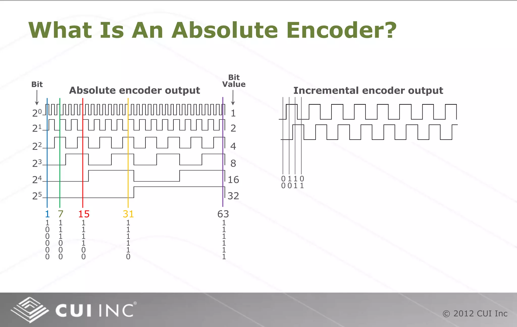
#11 Unlike incremental encoders that generate a simple chain of square waves, the absolute encoder generates a unique, digital ‘word’ for each position in its stated resolution. Because it is a digital device, resolution is expressed as an exponent of 2, i.e., 28, 210, 212, etc. The numbers on the right of the absolute output illustration represent the numeric value of the bit when it is ‘on’ or ‘high’. A 6 bit (26) absolute encoder, as illustrated above, can generate 64 unique, digital ‘words’ that represent 64 positions in one revolution. Five positions are illustrated above: At the blue line, only the 20 bit is high, so the output is 1. At the green line, the 20, 21 & 22 bits are all high; 1+2+4 = 7. At the red line, the 20, 21 & 22 and 23 bits are high; 1+2+4+8 = 15.
A major advantage that absolute encoders have over standard incremental encoders is that they offer much higher resolutions such as 212 (4,096)~216 (65,536), allowing for extremely fine position information which is required for high-precision operations. You will notice the illustration of the incremental encoder shows a repetitive train of 0s and 1s. No absolute position can be obtained.
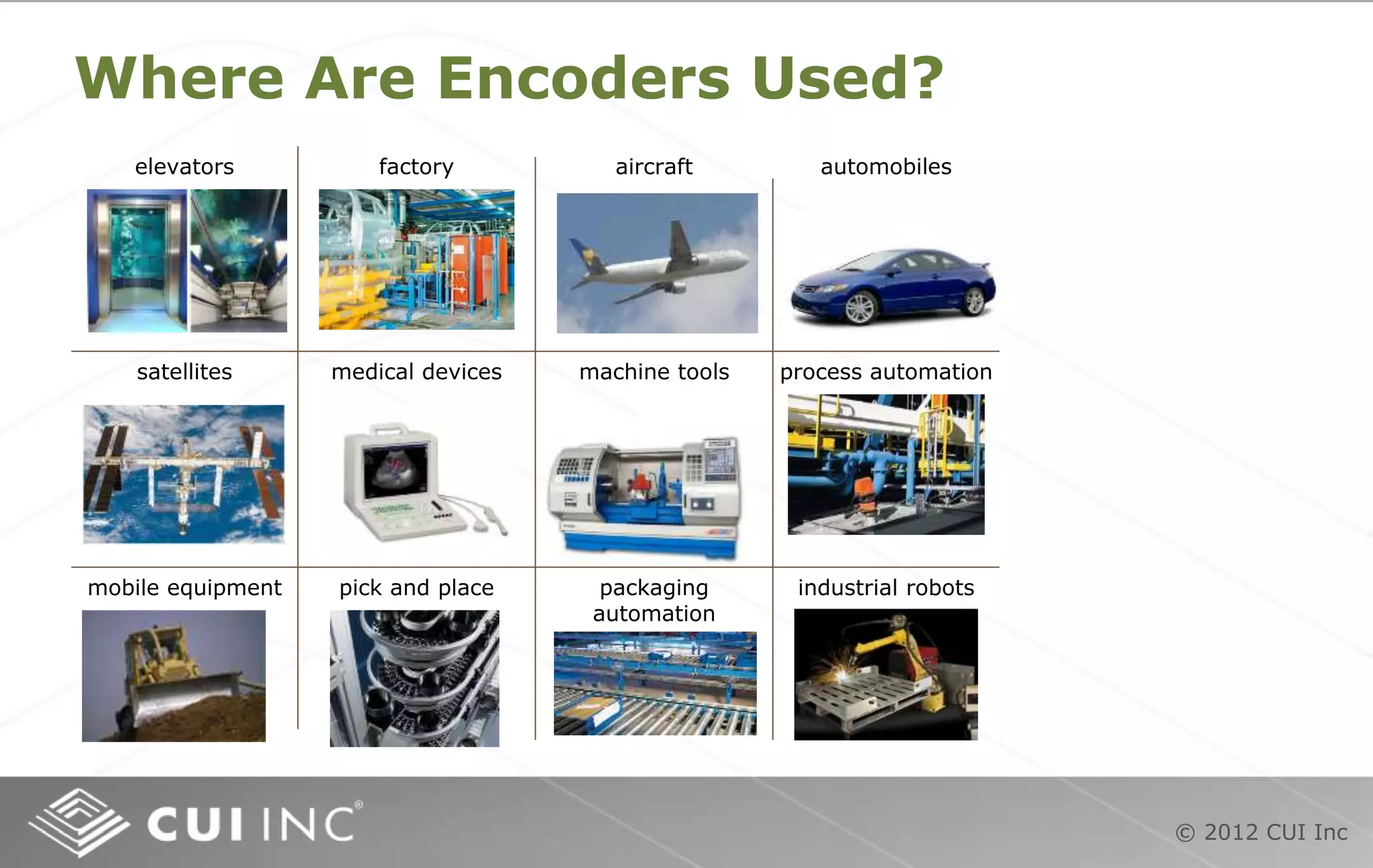
#12 These are just a few of the many devices that absolute encoders are used in. Absolute encoders are typically used for repetitive operations, in applications where exact position must be known even if power is lost and regained, in life-critical devices and devices that aren’t often used. Aerospace, medical devices, material handling, robotics, heavy machinery, and manufacturing are just a few of the market sectors that use absolute encoders.
#13 There are a handful of technology platforms currently in use today to provide absolute positioning information. Mechanical encoders are very low cost, low resolution encoders that generate output code by making and breaking circuits. They are most often used as panel controls such as the volume control on a stereo. Optical absolute encoders are mid-range to high cost and use infrared LEDs and phototransistors to generate output code. Magnetic absolutes can be low to high cost, low to medium resolution and generate output code by detecting changes in magnetic flux fields. Fiber optic absolutes are typically used in explosion-proof applications and are extremely expensive. They use a laser and phototransistor to generate output code. The AMT203 is a low cost, high resolution absolute that generates output code by detecting changes in the frequency of a signal modulated by capacitive reactance. Although capacitive encoders are relatively new, the code generation technology has been used reliably in digital calipers for over two decades.
#14 The revolutionary AMT203 consists of three basic parts as shown in the photograph. The ac field transmitter emits a signal that is modulated by the metal pattern on the rotor as it turns. The sinusoidal metal pattern on the rotor creates a signal modulation that is repetitive and predictable. This occurs as a result of varying capacitive reactance between the signal generated by the transmitter and the metal on the rotor. The field receiver uses a proprietary ASIC to convert the modulated signal into output pulses that can be read by the same circuits used to receive optical encoder output.
If you have ever used digital calipers, you are already familiar with capacitive encoding. The code generation used in digital calipers for decades is the same technology built into the AMT203. This capacitive code-generation technology has been shown to be reliable, accurate, economical and rugged enough to outlast other types of absolute encoders.
#15 The AMT203 is unique among modular, absolute encoders because it utilizes capacitive instead of optical technology. This eliminates handling of the sensitive optical disk and issues related to LED burnout or lens contamination. It also simplifies the assembly process leading to reduced manufacturing cost. Lower current consumption, programmability, higher gap tolerance, expanded temperature range, reduced time to implement and low acquisition cost add to capacitive technology’s competitive advantage vs. optical.
#16 The AMT203 offers a number of key specifications and features that differentiates it vs. the competition. Mechanically, it is low profile and light-weight. The encoder is rugged, offering a broad temperature range and immunity to dust and particulates. It is green, with a current consumption much lower than optical encoders. Finally, the AMT203 is flexible, offering a programmable zero position and a multitude of mounting options.
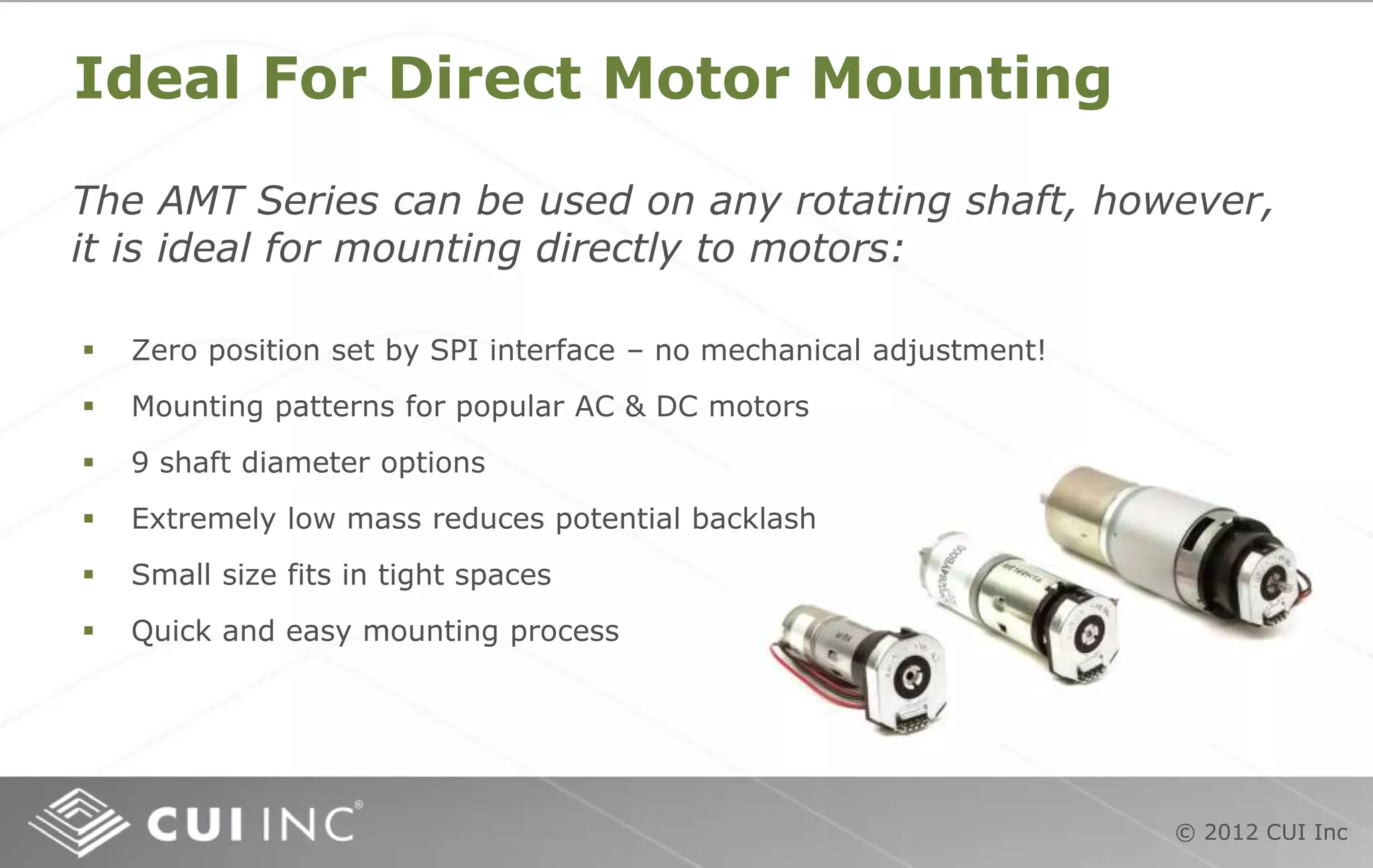
#17 With 4 mounting options and 9 shaft bushings the AMT203 encoder can easily mount to almost any motor. Its low mass disc means virtually no additional backlash or increased moment of inertia making it a more reliable component for measuring and controlling the motor. Its small size allows for mounting in tight spaces and to small motors.
Zero position is often used in an application as the ‘home’ position, the point where all operations controlled by the encoder feedback begin. The AMT is different than other encoders in that the zero position can be easily set through the SPI interface or by using the AMT203 Demo Board. In either case, no mechanical positioning, which can be tricky and time-consuming, is necessary.
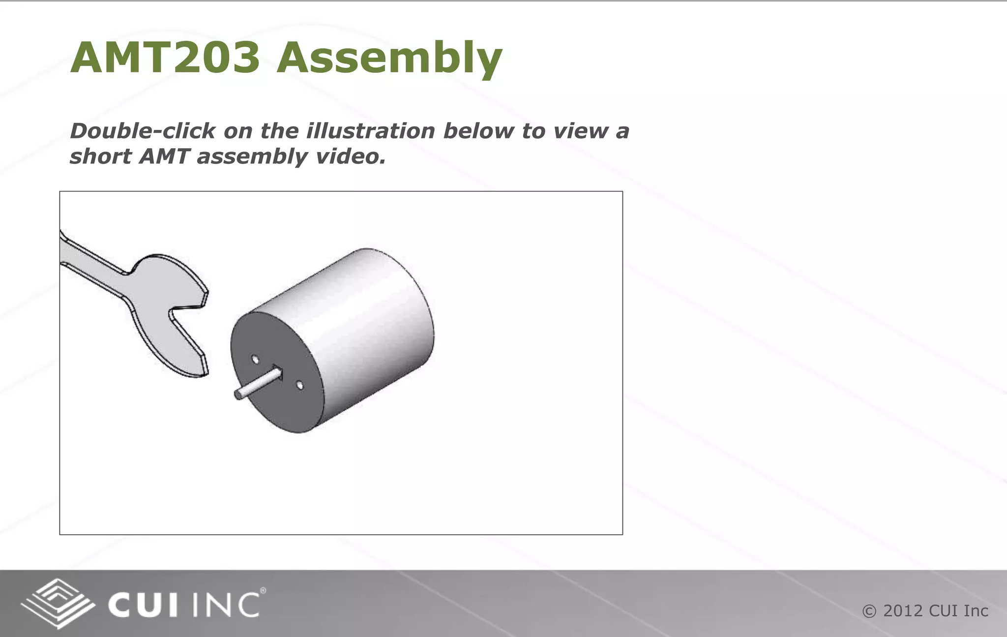
#18 With the disk built-in to the top cover, assembly is very quick and easy. Just snap the shaft adapter over a selected sleeve on the back shaft of a dc motor, align and mount the selected base unit with one of the mounting hole options, and snap the top cover into place in seconds. The top cover of the AMT203 houses the circuitry that detects the motor shaft rotation. These top covers are metal, adding durability. The circuit boards that are responsible for detecting rotation are mounted into the top cover casing to make assembly even easier.
#19 With the disk built-in to the top cover, the assembly is very quick and easy. Just snap the shaft adapter over a selected sleeve on the back shaft of a dc motor, align and mount the selected base unit with one of the mounting hole options, and snap the top cover into place in seconds. The difference between the AMT102 and 103 is that the 102 has a straight output connector while the 103 has a right angle output connector.
#20 The AMT203-V kit comes with 9 color-coded sleeves that will adapt to 9 different motor shaft diameters. Typical absolute encoders on the market today fit only one motor size per sku. For example, if a manufacturer is utilizing motors with 2 mm, 5 mm and 8 mm shafts in their system, they must purchase three separate encoders. With four popular mounting patterns and nine shaft size options, the AMT203- V can fit all three applications under one sku. With the ability to adapt to almost any application, the AMT203 is the most flexible absolute encoder on the market today.
#21 The AMT203 demo board can be interfaced with a PC via USB cable or used on a stand-alone basis. The demo board comes with a sample AMT203 encoder, thumb drive with drivers and TCL software, power supply, interconnect cables and user guide. Data is exchanged via SPI (Serial Parallel Interface) link when connected to a PC or direct using the three membrane switches. It’s an excellent tool for evaluating the outstanding flexibility of the AMT203 absolute encoder.
#22 The AMT203 uses SPI (Serial Parallel Interface) protocol to communicate position information. SPI is very simple, synchronous protocol compatible with many other serial protocols like SSI, I2C, Microwire and others. It is a two-way communications protocol and data can be received by or sent from the master or slave device.
Unlike I2C there is no concept of transferring ownership of the bus i.e. changing bus master and there are no slave device addresses. SPI is a much simpler protocol and because of this you can operate it at speeds greater than 10MHz (compared with the 3.4MHz maximum for I2C). The AMT203 sends data to the master, usually a controller. In SPI, the controller can send data to the encoder on the MOSI line, but only the SCLK output from the master is required because the master does not typically create other data useful to the encoder.
#23 The AMT203-V kit and the AMT203-DMK demo kit are available immediately through Digi-Key. Click on the links to go directly to the Digi-Key product page.