Download to read offline
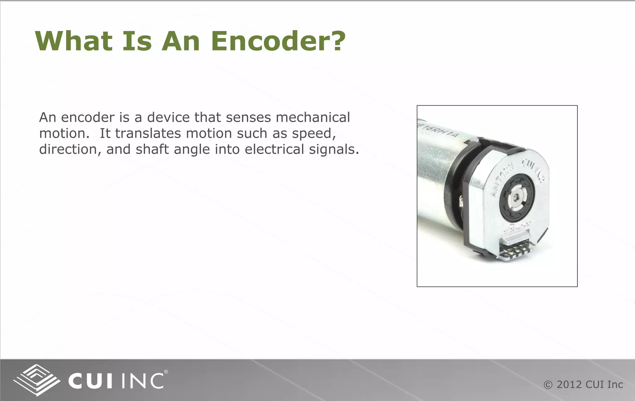
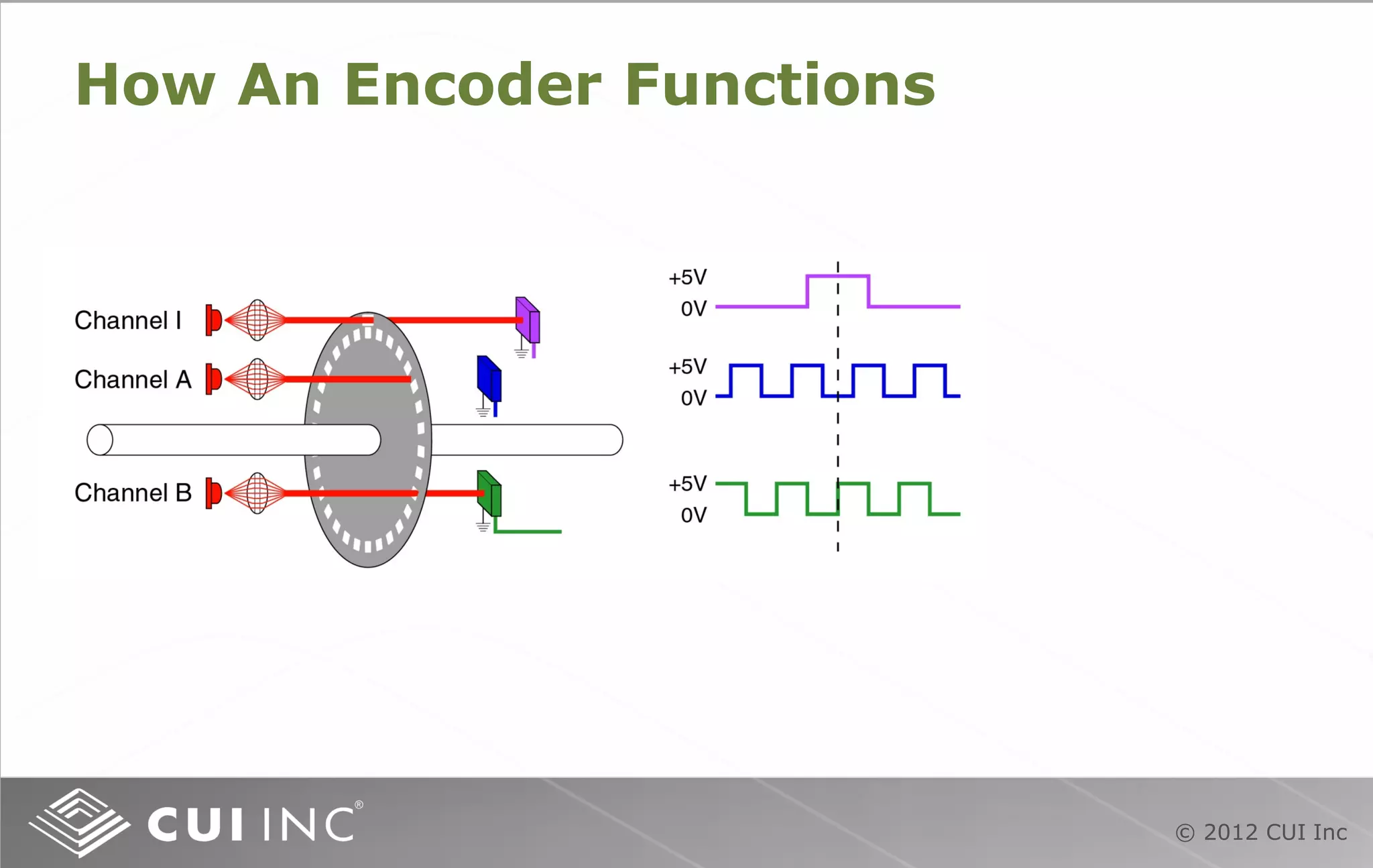
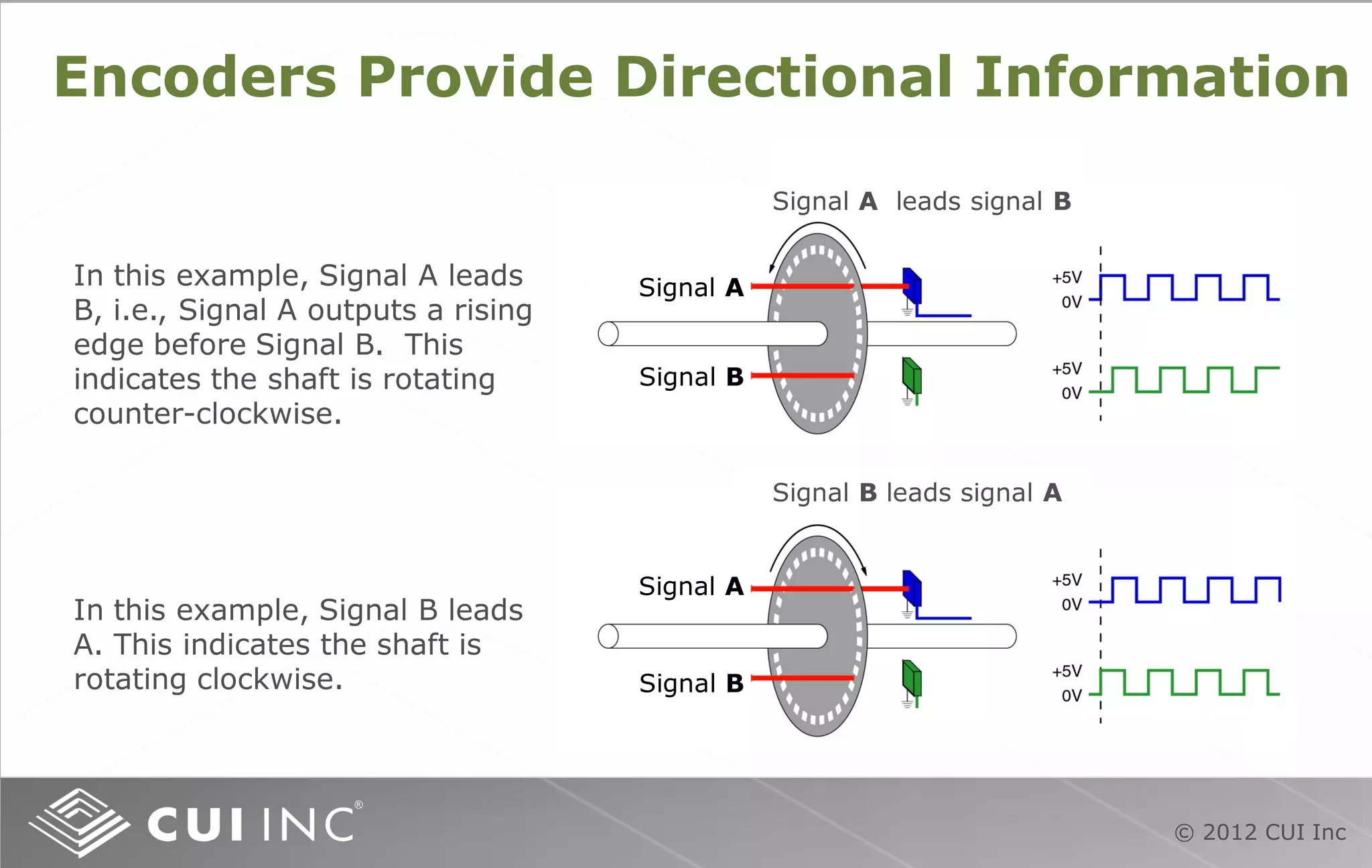
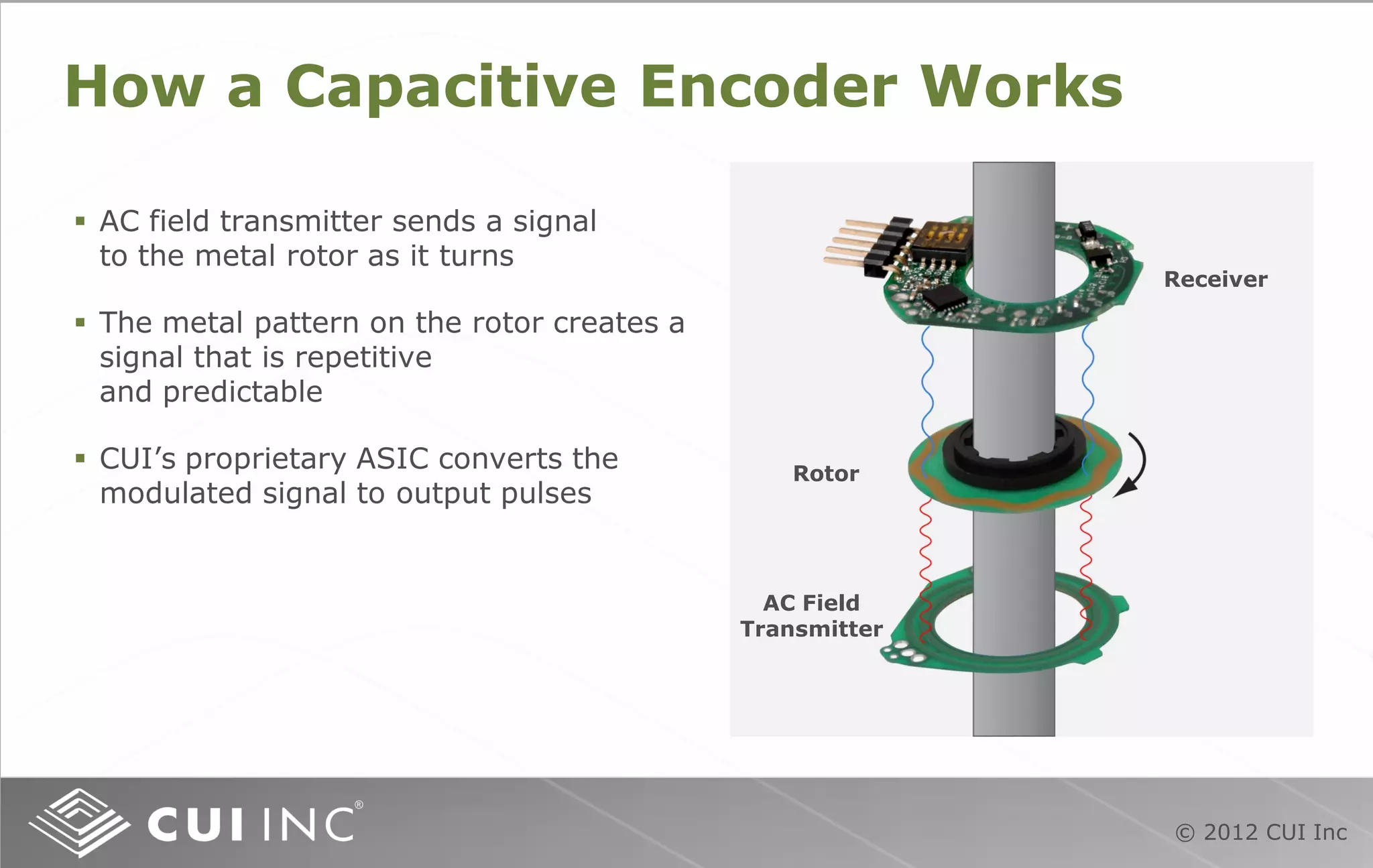
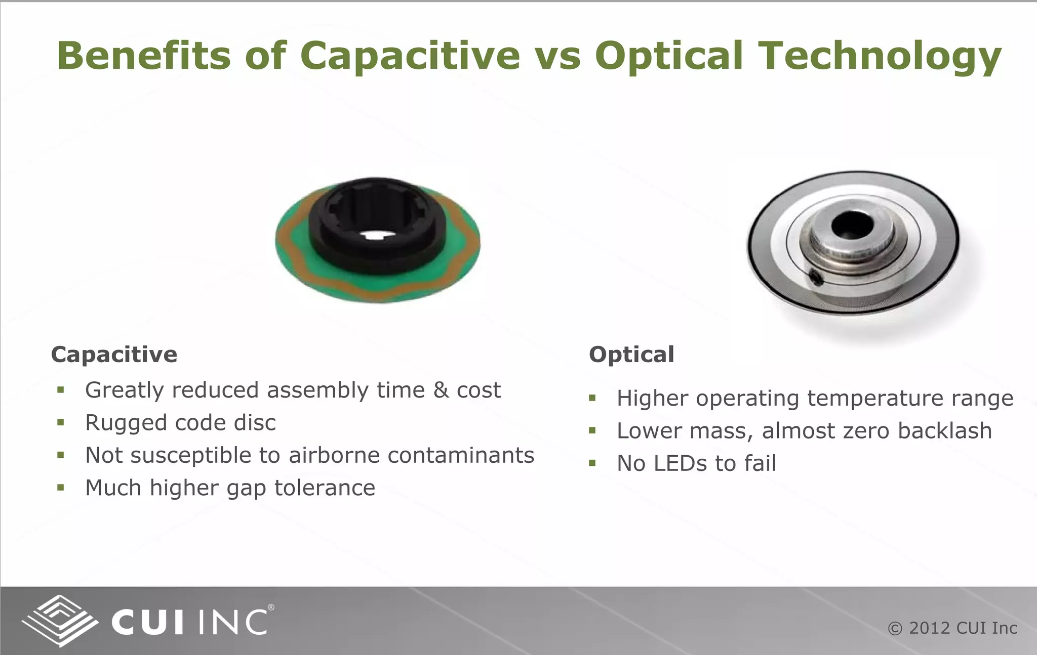
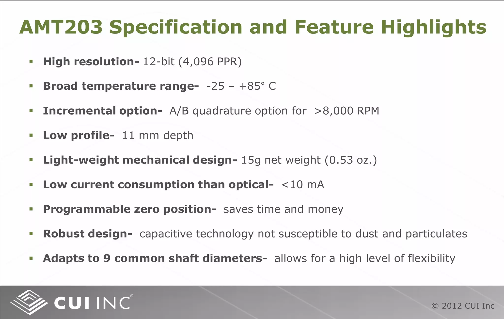
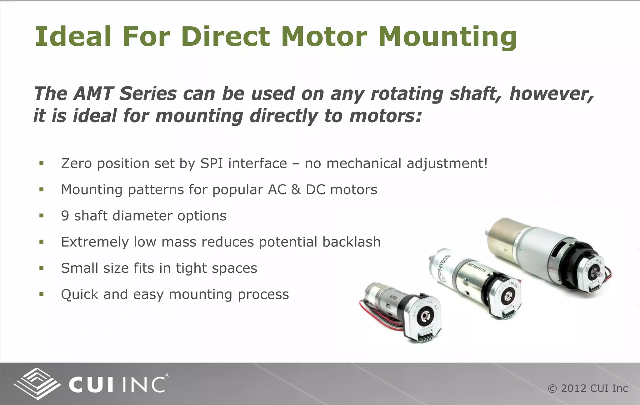
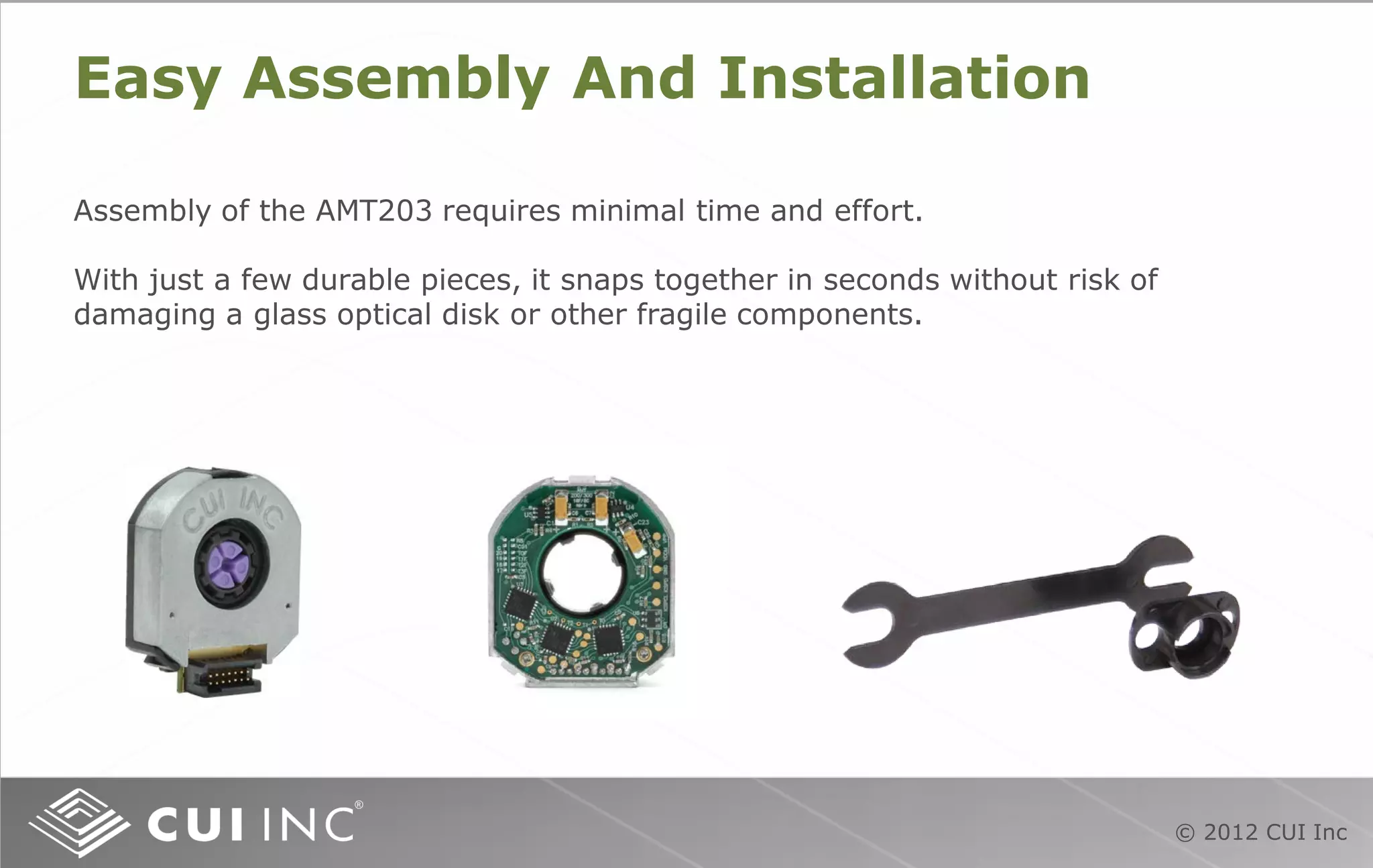
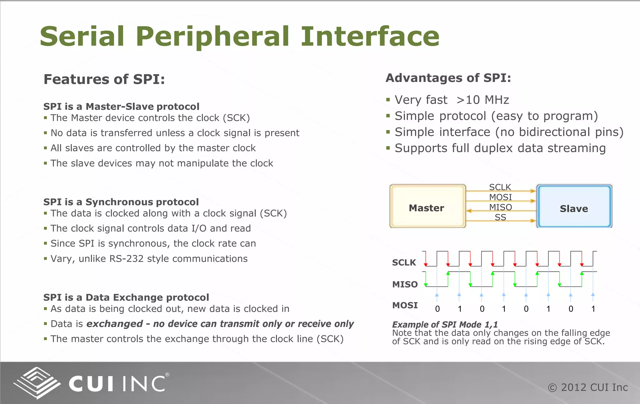
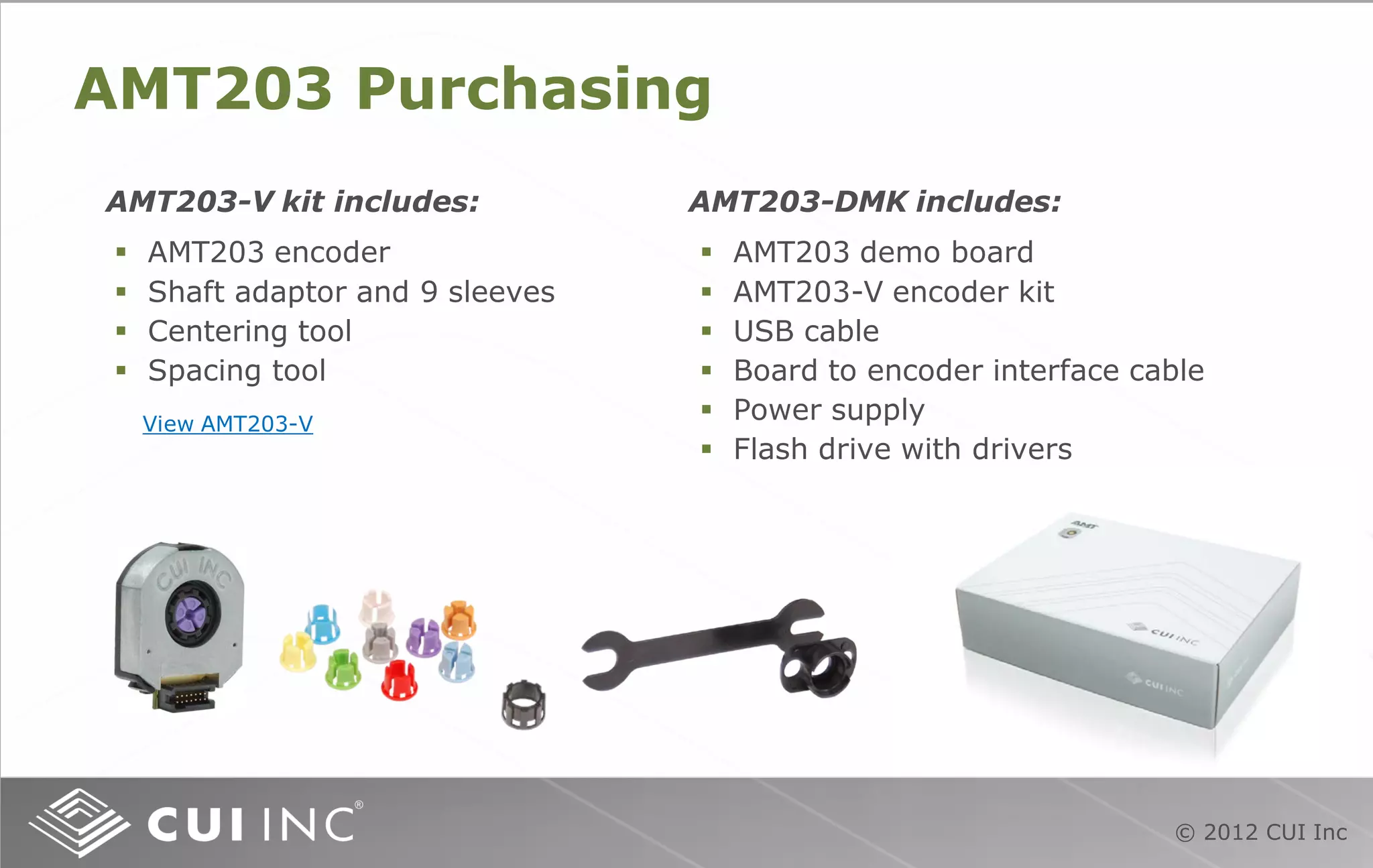


This document provides a training module on rotary absolute encoders, specifically the AMT203 absolute encoder produced by CUI Inc. It describes the functional theory of encoders, the components and operation of the AMT203, and its benefits over other encoder types. Installation and programming of the AMT203 using a demo board is also covered.


