Ch4 v70 system_configuration_en
•Download as PPT, PDF•
5 likes•2,266 views

TREINAMENTO EM AUTOMAÇÃO INDUSTRIAL SIEMENS PCS7

Recommended
More Related Content
What's hot
What's hot (20)
Viewers also liked
Viewers also liked (20)
Similar to Ch4 v70 system_configuration_en
Similar to Ch4 v70 system_configuration_en (20)
More from confidencial
More from confidencial (10)
Recently uploaded
Recently uploaded (20)
Ch4 v70 system_configuration_en
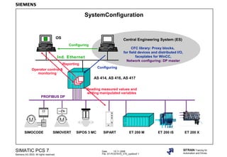
- 1. Date: 15.11.2006 File: ST-PCS7SYS_V70_systkonf.1 SIMATIC PCS 7 Siemens AG 2003. All rights reserved. SITRAIN Training for Automation and Drives SystemConfiguration PROFIBUS DP AS 414, AS 416, AS 417 Central Engineering System (ES) CFC library: Proxy blocks, for field devices and distributed I/O, faceplates for WinCC, Network configuring: DP master OS Ind. Ethernet SIMOVERTSIMOCODE SIPARTSIPOS 3 MC ET 200 M Operator control & monitoring Reporting Reading measured values and writing manipulated variables Configuring Configuring ET 200 iS ET 200 X
- 2. Date: 15.11.2006 File: ST-PCS7SYS_V70_systkonf.2 SIMATIC PCS 7 Siemens AG 2003. All rights reserved. SITRAIN Training for Automation and Drives
- 3. Date: 15.11.2006 File: ST-PCS7SYS_V70_systkonf.3 SIMATIC PCS 7 Siemens AG 2003. All rights reserved. SITRAIN Training for Automation and Drives System Configuration for PCS 7 Components PC ES/OS Terminal bus Plant bus Application WinCC application LAN onboard PC OS WinCC application CP 1613 NET-Pro Set PC station Station Configuration Editor (SCE) AS 01 C P U C P P S AS 02 C P U C P P S HW Config
- 4. Date: 15.11.2006 File: ST-PCS7SYS_V70_systkonf.4 SIMATIC PCS 7 Siemens AG 2003. All rights reserved. SITRAIN Training for Automation and Drives Configurable Components AS ES/OS
- 5. Date: 15.11.2006 File: ST-PCS7SYS_V70_systkonf.5 SIMATIC PCS 7 Siemens AG 2003. All rights reserved. SITRAIN Training for Automation and Drives AS HW Config
- 6. Date: 15.11.2006 File: ST-PCS7SYS_V70_systkonf.6 SIMATIC PCS 7 Siemens AG 2003. All rights reserved. SITRAIN Training for Automation and Drives Using HW Config to Configure the AS 1 3 4 2 Hardware catalog
- 7. Date: 15.11.2006 File: ST-PCS7SYS_V70_systkonf.7 SIMATIC PCS 7 Siemens AG 2003. All rights reserved. SITRAIN Training for Automation and Drives
- 8. Date: 15.11.2006 File: ST-PCS7SYS_V70_systkonf.8 SIMATIC PCS 7 Siemens AG 2003. All rights reserved. SITRAIN Training for Automation and Drives Exercise: AS HW Config (Central AS) CP DP CPU 417-4DP PS IM 153-2 SMSM SM SM MPI DP ET 200M ( UR1 or UR2) CP Eth PS 407 Slot 1 3 5 6 PROFIBUS address X1 X2
- 9. Date: 15.11.2006 File: ST-PCS7SYS_V70_systkonf.9 SIMATIC PCS 7 Siemens AG 2003. All rights reserved. SITRAIN Training for Automation and Drives
- 10. Date: 15.11.2006 File: ST-PCS7SYS_V70_systkonf.10 SIMATIC PCS 7 Siemens AG 2003. All rights reserved. SITRAIN Training for Automation and Drives
- 11. Date: 15.11.2006 File: ST-PCS7SYS_V70_systkonf.11 SIMATIC PCS 7 Siemens AG 2003. All rights reserved. SITRAIN Training for Automation and Drives Task: AS HW Config (PROFIBUS DP CiR Compatibility) PS 407 CPU 417-4DP PS IM 153-2 SMSM SM SM MPI DP PROFIBUS address ET 200 M (UR1 or UR2) CP DP CP Eth CiR
- 12. Date: 15.11.2006 File: ST-PCS7SYS_V70_systkonf.12 SIMATIC PCS 7 Siemens AG 2003. All rights reserved. SITRAIN Training for Automation and Drives Exercise: AS HW Config (PROFIBUS DP Set Parameters for CiR Object) 10 x 244 = 2440 I / 2440 O Max. bytes per slave Must be made available as PII/PIQ via the CPU properties!
- 13. Date: 15.11.2006 File: ST-PCS7SYS_V70_systkonf.13 SIMATIC PCS 7 Siemens AG 2003. All rights reserved. SITRAIN Training for Automation and Drives
- 14. Date: 15.11.2006 File: ST-PCS7SYS_V70_systkonf.14 SIMATIC PCS 7 Siemens AG 2003. All rights reserved. SITRAIN Training for Automation and Drives Exercise: AS HW Config (Set Parameters for PROFIBUS DP CiR Module)
- 15. Date: 15.11.2006 File: ST-PCS7SYS_V70_systkonf.15 SIMATIC PCS 7 Siemens AG 2003. All rights reserved. SITRAIN Training for Automation and Drives DP master buffer Inputs Outputs Exercise: AS HW Config (CPU Process Image Partition) AI P I P 1 DO P I P 2 IM 153 PIPI1 OB32 PIPO1 PIPI2 OB35 PIPO2 OB32 PIP1 OB35 PIP2 CPU OS 1 2 3 PIP Process image partition = PIPI (inputs) + PIPO (outputs) Trt
- 16. Date: 15.11.2006 File: ST-PCS7SYS_V70_systkonf.16 SIMATIC PCS 7 Siemens AG 2003. All rights reserved. SITRAIN Training for Automation and Drives
- 17. Date: 15.11.2006 File: ST-PCS7SYS_V70_systkonf.17 SIMATIC PCS 7 Siemens AG 2003. All rights reserved. SITRAIN Training for Automation and Drives Exercise: AS HW Config (Driver Concept/Symbolic Channel Names) CP DP CPU 417-4DP PS IM 153-1 SMSM SM SM MPI DP PROFIBUS address (UR1 or UR2) CP Eth PS 407 P I P 1 P I P 1 P I P 1 P I P 1 OB 32 <-> PIP 1 OB 35 <-> PIP 2 Name_channel_0 Name_channel_1
- 18. Date: 15.11.2006 File: ST-PCS7SYS_V70_systkonf.18 SIMATIC PCS 7 Siemens AG 2003. All rights reserved. SITRAIN Training for Automation and Drives
- 19. Date: 15.11.2006 File: ST-PCS7SYS_V70_systkonf.19 SIMATIC PCS 7 Siemens AG 2003. All rights reserved. SITRAIN Training for Automation and Drives Compiling and Downloading the AS HW-Config Download the hardware configuration only after the following steps have been carried out with NetPro: The network is configured and connections have been set up from the OSs to the monitored ASs. Connections were also configured between the devices (AS, AS) to allow data exchange during process control. See also chapter "Network Configuration". For testing purposes, you can also compile and download the AS configuration in the exercise now (the ES is not yet configured). For this to work, the Ethernet CP of the ES must be in "PG Operation" mode (see also the section "Configuring the Workstation").
- 20. Date: 15.11.2006 File: ST-PCS7SYS_V70_systkonf.20 SIMATIC PCS 7 Siemens AG 2003. All rights reserved. SITRAIN Training for Automation and Drives Setting the PG/PC Interface for the First AS Download S7ONLINE (STEP 7) ISO Ind Ethernet Realtek…
- 21. Date: 15.11.2006 File: ST-PCS7SYS_V70_systkonf.21 SIMATIC PCS 7 Siemens AG 2003. All rights reserved. SITRAIN Training for Automation and Drives Compiling the AS HW Config and Downloading in STOP Mode 1 2
- 22. Date: 15.11.2006 File: ST-PCS7SYS_V70_systkonf.22 SIMATIC PCS 7 Siemens AG 2003. All rights reserved. SITRAIN Training for Automation and Drives Exercise: Download the AS Hardware Configuration in RUN 1 3
- 23. Date: 15.11.2006 File: ST-PCS7SYS_V70_systkonf.23 SIMATIC PCS 7 Siemens AG 2003. All rights reserved. SITRAIN Training for Automation and Drives Exercise: Download the AS HW Config to the PLC (Check CiR Compatibility-1)
- 24. Date: 15.11.2006 File: ST-PCS7SYS_V70_systkonf.24 SIMATIC PCS 7 Siemens AG 2003. All rights reserved. SITRAIN Training for Automation and Drives Exercise: Download the AS HW Config to the PLC (Check CiR Compatibility-2)
- 25. Date: 15.11.2006 File: ST-PCS7SYS_V70_systkonf.25 SIMATIC PCS 7 Siemens AG 2003. All rights reserved. SITRAIN Training for Automation and Drives Exercise: Download the AS HW Config to the PLC (Check CiR Compatibility-3) ?
- 26. Date: 15.11.2006 File: ST-PCS7SYS_V70_systkonf.26 SIMATIC PCS 7 Siemens AG 2003. All rights reserved. SITRAIN Training for Automation and Drives Configuring the PC Station (Overview) Hardware description on the PC station Hardware description in the PCS 7 project Actual configuration Preset configuration With "PG operation" Commissioning Wizard Set PC station CP y CP x 1 2 Application WinCC application CP x CP y Station Manager Station Configuration Editor (part of PC installation) 1 2 3 4 125 Index/type 3 with "configured mode" Application WinCC application CP x CP y Station Manager 1 2 3 4 125 Index/type HW Config of the PC station (part of project) 4
- 27. Date: 15.11.2006 File: ST-PCS7SYS_V70_systkonf.27 SIMATIC PCS 7 Siemens AG 2003. All rights reserved. SITRAIN Training for Automation and Drives
- 28. Date: 15.11.2006 File: ST-PCS7SYS_V70_systkonf.28 SIMATIC PCS 7 Siemens AG 2003. All rights reserved. SITRAIN Training for Automation and Drives Set the PC Station (Modules)
- 29. Date: 15.11.2006 File: ST-PCS7SYS_V70_systkonf.29 SIMATIC PCS 7 Siemens AG 2003. All rights reserved. SITRAIN Training for Automation and Drives Set PC Station (Access Point)
- 30. Date: 15.11.2006 File: ST-PCS7SYS_V70_systkonf.30 SIMATIC PCS 7 Siemens AG 2003. All rights reserved. SITRAIN Training for Automation and Drives SCE (Station Configuration Editor Option)
- 31. Date: 15.11.2006 File: ST-PCS7SYS_V70_systkonf.31 SIMATIC PCS 7 Siemens AG 2003. All rights reserved. SITRAIN Training for Automation and Drives
- 32. Date: 15.11.2006 File: ST-PCS7SYS_V70_systkonf.32 SIMATIC PCS 7 Siemens AG 2003. All rights reserved. SITRAIN Training for Automation and Drives Exercise: SIMATIC PC Station/OS HW Config Windows network connections (via START Settings Control Panel Network Connections) Meaningful names for the LAN connections Installed Ethernet CPs
- 33. Date: 15.11.2006 File: ST-PCS7SYS_V70_systkonf.33 SIMATIC PCS 7 Siemens AG 2003. All rights reserved. SITRAIN Training for Automation and Drives Exercise: SIMATIC PC Station/OS HW Config
- 34. Date: 15.11.2006 File: ST-PCS7SYS_V70_systkonf.34 SIMATIC PCS 7 Siemens AG 2003. All rights reserved. SITRAIN Training for Automation and Drives
- 35. Date: 15.11.2006 File: ST-PCS7SYS_V70_systkonf.35 SIMATIC PCS 7 Siemens AG 2003. All rights reserved. SITRAIN Training for Automation and Drives Exercise: SIMATIC PC Station/OS HW Config 1 2 0 6 3 45
- 36. Date: 15.11.2006 File: ST-PCS7SYS_V70_systkonf.36 SIMATIC PCS 7 Siemens AG 2003. All rights reserved. SITRAIN Training for Automation and Drives Exercise: SIMATIC PC Station/OS HW Config Station Configuration Editor was created when PCS 7 was installed on the PC Is configured according to the subsequent use of the PC as an ES and/or OS SIMATIC PC station HW Config is configured in the project in the SIMATIC Manager and downloaded to the target PC. S7ONLINE PC local 1 2
- 37. Date: 15.11.2006 File: ST-PCS7SYS_V70_systkonf.37 SIMATIC PCS 7 Siemens AG 2003. All rights reserved. SITRAIN Training for Automation and Drives Calling Up NetPro
- 38. Date: 15.11.2006 File: ST-PCS7SYS_V70_systkonf.38 SIMATIC PCS 7 Siemens AG 2003. All rights reserved. SITRAIN Training for Automation and Drives
- 39. Date: 15.11.2006 File: ST-PCS7SYS_V70_systkonf.39 SIMATIC PCS 7 Siemens AG 2003. All rights reserved. SITRAIN Training for Automation and Drives Click twice -with a pause between clicks - and then rename.
- 40. Date: 15.11.2006 File: ST-PCS7SYS_V70_systkonf.40 SIMATIC PCS 7 Siemens AG 2003. All rights reserved. SITRAIN Training for Automation and Drives Setting Up a Connection (1)
- 41. Date: 15.11.2006 File: ST-PCS7SYS_V70_systkonf.41 SIMATIC PCS 7 Siemens AG 2003. All rights reserved. SITRAIN Training for Automation and Drives Setting Up a Connection (2) Change to, for example OS01_AS01
- 42. Date: 15.11.2006 File: ST-PCS7SYS_V70_systkonf.42 SIMATIC PCS 7 Siemens AG 2003. All rights reserved. SITRAIN Training for Automation and Drives Downloading a Connection
- 43. Date: 15.11.2006 File: ST-PCS7SYS_V70_systkonf.43 SIMATIC PCS 7 Siemens AG 2003. All rights reserved. SITRAIN Training for Automation and Drives Cross-Project View Standard View Cross-Project View
- 44. Date: 15.11.2006 File: ST-PCS7SYS_V70_systkonf.44 SIMATIC PCS 7 Siemens AG 2003. All rights reserved. SITRAIN Training for Automation and Drives S7 Connections (Stations in Unknown Projects)
Editor's Notes
- ContentPage System Configuration for PCS 7 Components..................................................................................3 Configurable Components................................................................................................................4 Using HW Config to Configure the AS..............................................................................................6 Exercise: AS HW Config (Central AS)..............................................................................................8 Task: AS HW Config (PROFIBUS DP CiR Compatibility).................................................................11 Exercise: AS HW Config (PROFIBUS DP Set Parameters for CiR Object)........................................12 Exercise: AS HW Config (Set Parameters for PROFIBUS DP CiR Module)......................................14 Exercise: AS HW Config (CPU Process Image Partition)..................................................................15 Exercise: AS HW Config (Driver Concept/Symbolic Channel Names)...............................................17 Compiling and Downloading the AS HW-Config...............................................................................19 Setting the PG/PC Interface for the First AS Download.....................................................................20 Compiling the AS HW Config and Downloading in STOP Mode........................................................21 Exercise: Download the AS Hardware Configuration in RUN............................................................22 Exercise: Download the AS HW Config to the PLC Check CiR Compatibility-1).................................23 Configuring the PC Station (Overview).............................................................................................26 Set the PC Station (Modules)...........................................................................................................28 Set PC Station (Access Point)..........................................................................................................29 SCE (Station Configuration Editor Option)........................................................................................30 Exercise: SIMATIC PC Station/OS HW Config.................................................................................32 Calling Up NetPro............................................................................................................................37 Setting Up a Connection .............................................................................................................40 Downloading a Connection...............................................................................................................42 Cross-Project View..........................................................................................................................43 S7 Connections (Stations in Unknown Projects)...............................................................................44
- ConfigurationA PCS 7 environment consists of ASs (S7 components with suitable I/O), PCs used as an ES or OS and networks between these components. There is an actual configuration and a preset configuration for each component. In addition communication connections must be set up between the stations. Actual configurationWith an AS, this is determined by the specific structure of the available hardware (rack, power supply, CPU etc.). In our case, the hardware was provided in our training room. With a PC (used as ES or OS), a virtual structure is created using SIMATIC tools for the workstation configuration (Set PC station, or Station Configuration Editor). You need to set up the structure yourself (this is generally done when the PCS 7 software is installed on the PC). With V7.0 and higher, this can be simply carried out from the central ES (Configure Station). Preset configurationThe preset configuration is created in the SIMATIC Manager within a project on the ES by using the HW-Config tool in the project. It contains project-specific parameter settings for the devices used. After completion, the preset configuration must then be transferred via the network from the ES to the respective station (AS or PC). In doing so, the load procedure must find the components of the preset configuration in the actual configuration. ConnectionNetPro is used for this. Connections are created between: ES-AS, OS-AS, AS-AS (if the latter need to exchange data among themselves). You also need to download these connections to the respective stations. RemarkAll tools are integrated in the ES software and can either be called directly or in the context of the components to be configured.
- ConfigurationHardware components are used within the project. These include the automation systems (AS), PCs as operator stations (OS) or engineering stations (ES), and the networks. ComponentsIn the multiproject, select the required project, then right-click and select select Insert New Object and then as required: &quot;SIMATIC 400 Station&quot; for an AS &quot;SIMATIC PC Station&quot; for an ES or OS &quot;Industrial Ethernet&quot; for the plant bus or terminal bus,etc. When you select the object to insert, a symbol is generated to represent each device and serves as access point to the configuration. HW ConfigThe &quot;Hardware Configuration&quot; tool or &quot;HW Config&quot; for short is used for this. HW-Config is used in the same way for both AS and ES. ASTo configure the AS, use the mouse to select the symbol representing the required AS in the SIMATIC Manager (component view), then right-click and select Open Object The tool is launched. As an alternative, you can also double-click the hardware symbol in the right pane. ESTo configure the ES, use the mouse to select the symbol representing the required PC in the SIMATIC Manager (component view), then right-click and select Open Object The tool is launched. As an alternative, you can also double-click the configuration symbol in the right pane of the SIMATIC Manager.
- HW-ConfigTo start, the configuration should reproduce the configuration of the devices. The example in the slide shows an AS configuration. The components shown here offer settings screens (usually accessible via the object properties). If the configuring engineer is knowledgeable about the options available and application at hand, he or she can optimize the components&apos; settings offline first. Then these settings need to be supplied to the devices (by online download to the target systems).
- Using HW Config You have created one project with an AS and one with an OS. The hardware configuration must be adapted to the AS and OS you are using. In doing so, the parts lists for the ASs and PCs in use must be taken into account. TermsThe HW Config tool refers to a station (AS or PC). In the right pane, a tree structure displays the SIMATIC components (hardware catalog). After selecting a component (arrow 2 in the slide), the associated Order No. and a brief description are displayed in the comment field (arrow 3). If you have not been able to locate the module (as it is not a current PCS 7 module or is an older module) select the &quot;Standard&quot; hardware profile (arrow 1 in the slide) and search again. There you will find all S7 modules that are known in the current version of the SIMATIC Managers. TipIf you know part of the order number or designation, you can enter it in the Find box and click the button (arrow 4) to find the module. The search is only conducted for the selected profile. Please note that the part designation can occur multiple times! (If this is the case, continue the search.) PastingIn the SIMATIC Manager select the station/AS in component view, then right-click and select Open to open the HW Config.
- Then proceed as follows: Search in the catalog and check the order number and if necessary the firmware version of the racks, power supply, and CPU in use (arrow 3). Use a drag-and-drop operation to insert the located modules in the left window. Select the module in the left screen, then right-click and select Object Properties… then set the parameters for the module. ReplaceTo replace a rack (or a module inserted in the rack) search for the new, required module in the hardware catalog. Take the hardware profile setting into account when doing so. The comment field (arrow 3) displays the corresponding order number and brief description for the selected component (arrow 2). Select the correct component, &quot;drag&quot; it with depressed left mouse button across to the rack/module symbol and drop it there. If the exchange is possible, a message is displayed with the order numbers of the two components and must be acknowledged. If the exchange is not possible (because the old/new components are not compatible), the mouse pointer will change to a crossed circle. In this case, the settings of the old module should be documented before deleting the module and replacing it with a new one. Then transfer the settings as appropriate or make new settings. NoteIf you have selected an incorrect slot, you can drag the module to another location with the mouse. The new location must be free and wide enough (i.e. correspond to the number of slots required by the module to be displaced). RemarkThe catalog profile (arrow 1 in the slide) was set up with the PCS 7 installation. You can edit the profile (s7hpro0) that is automatically created by selecting Options -&gt; Edit Catalog Profile Here you use the familiar Windows procedure to copy objects from the standard profile (one window) to the new profile (the other window). After completion, the new profile can be saved via Profile -&gt; Save as... The newly created profile is offered for selection in the profile box.
- ExerciseConfigure the modules for the central part of your AS. Use the parts list for your AS as your guide! (The example refers to the &quot;Saarbrücken&quot; training room in the Mannheim Training Center.) --------------------------------------------------------------------------------------------------------- Steps1. Insert the rack (UR=Universal Rack) 2. Insert the power supply (PS=Power Supply) 3. Insert the CPU or supplement the integrated DP interface. Rename the DP subnet and check properties 4. Insert and set CP for PROFIBUS DP (if available) Register CP 443-5 Ext as DP master Rename the DP subnet and check properties 5. Insert and set CP for Ethernet Create a new Ethernet network for the plant bus and rename it Assign or verify MAC address, disable TCP/IP protocol ---------------------------------------------------------------------------------------------------------- Procedure Open HW ConfigIn the project, select the ASxx to be configured (your AS), and right-click and select Open object Use the hardware catalog to locate and configure the components (rack, PS, CPU, CP and I/O modules) in the HW Config for the station. If you cannot see the catalog, select View -&gt; Catalog to activate it.
- Rack In the hardware catalog select the desired rack SIMATIC 400 -&gt; RACK 400 -&gt; UR1 then use drag & drop to move it to the top left window. Notice!For the catalog component you have highlighted, check the detail specifications in the lower catalog window pane (order No. and comment) so you can insert the correct components. It is possible that the CPU will not start up if you insert a component incorrectly! The slots in the rack are listed in rows. You can now populate each slot (you can also use &quot;drag & drop&quot;). Power supplySelect slot &quot;1&quot;. In the hardware catalog, selectSIMATIC 400 -&gt; PS 400 -&gt; e.g. PS 407 10A and position it on row 1. This 10 A power supply occupies 2 slots. CPUSelect the correct CPU from the hardware catalog (for example) SIMATIC 400 -&gt; CPU 400 -&gt; CPU 417-4 -&gt; V3.1 and drag it to the next free row (row 3). The CPU with the integrated DP interface occupies two slots. The Properties screen opens. Select the New button to create a new DP network and enter a meaningful name (e.g. DP_subnet1, or DP_AS01_int1, or DP_AS01_ext3). In the properties for the selected network check whether the DP protocol and the desired baud rate are set (default 1.5 Mbaud). The image displayed now represents the PROFIBUS DP with the &quot;DP master system (1)&quot; identifier. The ET 200M is later appended to this. Networking CPU via MPI This is no longer necessary with Version V6 and higher. RemarkThe new Ethernet CP from 6GK7 443-1EX11-0XE0 V2 supports direct addressing of the card via the known MAC address of the Ethernet CP, therefore, the initial loading via MPI is no longer necessary. Additional DP subnetIf an additional CP is connected in the rack for another DP subnet (such as the CP 443-5 Ext), this CP must be inserted in the rack in HW Config and be connected with a DP subnet (as the second DP master). In the HW catalog, select: SIMATIC 400-&gt;CP 400-&gt; CP 443-5 Ext, select the correct CP and use &quot;drag & drop&quot; to move the CP to the correct rack slot. In the screen overlaid for the PROFIBUS interface for the CP, select NEW to create a new DP network and then rename the network (for example, DP_Subnet2).
- CP as DP masterHighlight the CP 443-5 Ext in the rack, right-click and select Insert DP Master System to name this system as the master for the new subnet. You can use the graphically displayed subnet for additional ET 200M devices or for PROFIBUS PA devices via DP/PA link/coupler modules. If you do not want to configure the CP (no DP hardware is connected, for example), you must disconnect it from the power source (remove it from the rack). If it is present in the rack but not in the hardware configuration, the CPU (depending on the firmware version) may not start up (remain in STOP mode) or may not be downloaded. Therefore, if this CP exists in the hardware, it must also be entered in the HW Config. Ethernet CPEthernet is used as the plant bus by default. Insert the CP in the HW Config. In the HW catalog, select SIMATIC 400-&gt;CP-400-&gt;CP 443-1-&gt; &quot;Concrete CP&quot; and position it in the rack. In the overlaid &quot;Ethernet Interface Properties&quot; screen -&gt; Parameters tab, click the New button Then, create a new Ethernet subnet (if you have not already done so), rename the subnet (e.g., &quot;Plant bus&quot;) and select this bus to identify the CP as being networked. Set a unique MAC address in the project, taking into account other nodes physically present on the bus that are not part of this project. It is advisable to use the ISO transport protocol for small networks as it provides higher performance. However, if you want to communicate over more spread-out networks that are connected with routers, use the ISO-on-TCP transport protocol instead. Please note the address suggestion made in the parts list of your training automation system and deactivate the IP protocol (clear the check box). RemarkThe hardware configuration is downloaded in a later part of the exercise. Here, the AS is loaded directly via the known MAC address of the Ethernet CP for the first time. For this to work, the access point S7ONLINE must be active on an Ethernet-capable CP that is connected to the plant bus. (additional settings are described in the chapter &quot;Configuring the Workstation&quot; under Setting the PC Interface). The download also provides the CPU its parameter settings via the Ethernet CP (therefore the CPU is configured during this procedure). If you change the PC interface to the integrated Ethernet CP (LAN card or CP 1613), you can then download and debug additional data (hardware configuration and subsequent software) over the plant bus.
- ExerciseConfigure the distributed I/O (ET 200M). The configuration is to allow changes in runtime (CiR=Configuration in Run). Please refer to the parts list for your training automation station. ------------------------------------------------------------------------------------------------------- Steps1. Activate CiR compatibility 2. Set parameters for CiR object (reserve address range) 3. Set parameters for CiR module 4. Insert and configure I/O modules 5. Set process image partitions (CPU and I/O modules) 6. Assign symbolic names for the I/O channels 7. Compile and download (after changing the PC interface)! --------------------------------------------------------------------------------------------------------- CiR Compatibility (For Distributed I/O Only) CiRAdditions are to be made to the distributed I/O during runtime, without stopping the CPU. Select the DP master system (1) shown in the preceding graphic on the integrated DP interface of the CPU, right-click and select Activate CiR compatibility As a result a so-called CiR object is represented on the PROFIBUS DP. This object needs to be parameterized with regard to future additions of I/O.
- CiRThen right-click and select Properties to open the screen form above. The CiR object must retain resources for future DP/PA slaves. Each slave requires up to 244 bytes (can also be less, depending on the actual I/O modules). There is also a maximum limit for the number of slaves that can be inserted in the subnet online. 1. The guaranteed number of DP slaves (ET200, DP field devices) must be parameterized in relation to future additions. If no &quot;Extra Settings&quot; are selected, the sum of input and output bytes is automatically displayed. 2. They must be taken into account as sum values for the settings in CPU Properties -&gt; Cycle/Clock Bit Memory tab -&gt; Size of the process images (for all DP slaves on all subnets). The CPU properties cannot be changed online! NoteThe maximum CiR synchronization time has a default setting of 1000 ms. The time associated with the current configuration is displayed in the properties of the CiR object. The default time and the CiR download process can be influenced in the software. To this end, the system function SFC104 &quot;CiR&quot; can be called in a CFC (from the &quot;Standard Library&quot;). By parameterizing and downloading this, the CiR process can be influenced without stopping the CPU.
- In the HW catalog, under PROFIBUS DP -&gt; ET 200M select your version (e.g. IM153-2) and use the mouse to drag it onto the CiR object. Specify the PROFIBUS DP address for the ET 200M on the displayed screen (as set on the address switches for the IM). After closing the screen, the associated frame is displayed with a maximum of 11 slots (for I/O modules you can use slots 4 to 11). NoteNot all IM 153-2 modules are CiR-compatible (pay attention when ordering). Currently (V6.1) the 153-2 HF and 153-2 HF FO in the V6.1 hardware profile are suitable for CiR.
- As the selected IM 153-2 supports CiR, a CiR module is offered in the lower part of the window from slot 4. I/O ModulesTake the I/O modules and position them on top of this CiR module in the ET 200M table (as previously for the station, but now with modules from the ET 200M / IM 153-2 directory). This way the CiR module is shifted one place to the right, ready to receive the next I/O module. Note: AddressesThe CiR module reserves an address range for inputs and outputs (the total of which is less than 244 bytes - they can be addressed via the slave). Using the module properties, you should reserve sufficient address space for modules to be inserted at a later point in time. If you want to add address space later, you must switch the CPU to Stop mode. For example, if the planned configuration is one ET 200M for 8 modules (the corresponding bus modules (hardware) must be installed right from the start), and if the initial installation is equipped with 5 AI modules (8-channel), this means that 5x8x2=80 bytes input addresses are used. If you would like to add identical modules to the three remaining slots while the CPU is in Run mode, you will need to have reserved 8x8x2=128 bytes input addresses during the initial setup. 1 word=2 bytes per analog value are required. Note about module replacement When using PCS 7 you can replace modules during operation. Select the ET 200, and right-click and select Object Properties -&gt; Operating Parameters tab Then select the option &quot;Module replacement during operation&quot;. The bus modules listed here must be installed in the rack. If you forget to set this option and replace a module later during runtime, a rack failure message is issued (as if all modules had failed). The power supply for IM is not configured, but an external 24 V supply is possible.
- Process ImageThe DP master (CP or integrated DP interface on the CPU) cyclically scans the PROFIBUS DP subnet (circular arrow 1 in the slide). In doing so it passes data to the slaves (e.g. ET 200M for passing to the output modules) and reads back data from the slaves (which acquired them from the input modules). The data are passed through an IM internal buffer. TtrDuring each cycle, the DP master writes/reads values to/from all its slaves. The buffer content forms an image of the inputs and outputs of the modules. The cycle time is called Ttr = Target rotation time and is displayed in the properties of the CiR object, here IM 153. The DP update cycle runs independently of the CPU program, but must be at least as fast as the fastest program that processes the process values. For evaluation in the user programs, the intermediately stored input data from the operating system are copied at a defined point in time from the buffer to a CPU memory area and output data copied from there are written back to the buffer at a different point in time. The programs can then gain read (I) and write (O) access to this &quot;process image&quot; memory area. SynchronizationThis ensures that the programs are working with consistent process data. This means that the operating system must provide for the updating of the process input image and freeze it, before starting the program. After the program has been executed and commands have been written in the process output image, the output image is sent to the DP master. However, as process signals and their associated processing operate at selectable repetition rates (slow/fast processes), it is necessary for their synchronization to match as well.
- Process image partitionThe CPU offers OBs with different speeds in which the user can execute programs. You can assign a process image partition to the OBs in the CPU properties - Assign PIPs (e.g. OB32&lt;-&gt;PIP1, OB35&lt;-&gt;PIP2, OBx&lt;-&gt;PIPs, where n=1 to 16 is dependent on the CPU). At the same time a suitable PIP must be assigned for the individual I/O modules in their properties. Driver blocks are used in the PCS 7 software to input and output process data. These driver blocks must run in the same OB that updates the PIP of the scanned I/O module. NoteIt is useful when wiring the signals between modules to differentiate between slow and fast signals. A module should be assigned to a PIP that is capable of delivering signals to the software at sufficient speeds such that the fastest connected signal is processed currently. If signals are mixed on the module, this causes slow signals to be read quickly, wasting computing time. Remember:If you want many, it cannot be fast. If you want fast, it cannot be many. The CPU cannot continuously work in overload. After a programmed, but limited time this leads to CPU stop!
- ExerciseThe process image partitions are to be updated on the CPU: PIP &quot;1&quot; by OB32 and PIP &quot;2&quot; by OB35. The I/O modules (in the example) must be assigned to process image partition &quot;1.&quot; Give the individual channels of the I/O modules symbolic names as listed in the parts list for your AS. ---------------------------------------------------------------------------------------------------- Steps1. Select CPU symbol, open object properties 2. Cyclic Interrupt tab: assign PIP to the OBs 3. Cycle/Clock Bit Memory tab -&gt; check OB85 call 4. Assign symbolic names for I/O channels ------------------------------------------------------------------------------------------------------ Process image partitionThe CPUs (from about 1998) support process image partitions. The process image partition is defined in the CPU and for each I/O module (see next section). The process image is updated by the system through connection to an OB you selected. The procedure is as follows. Select the CPU. Open its Object Properties. Select the &quot;Cyclic Interrupt&quot; tab. For example, for OB32, select process image partition &quot;PIP1&quot;. For OB35, select process image partition &quot;PIP2&quot;. Select the &quot;Cycle/Clock Bit Memory&quot; tab. Check or make the following settings: OB85 call with I/O access error: With incoming or outgoing errors only Size of process input (output) image: both &gt;= 1024 (default setting depends on the CPU used)
- Setting parameters for I/O modules In the upper window, select the ET 200M you want to configure. In the lower window, select the individual line for the relevant module. Then, right-click and select Object Properties -&gt; Addresses tab Click the &quot;Process Image&quot; field. Select the process image partition you want (such as &quot;PIP1,&quot; according to the OB - process image partition assignment for the CPU made in the previous section). Repeat the procedure for each I/O module. This is how you determine how quickly and frequently the CPU updates the data for the individual module. &quot;Inputs/Outputs&quot; tab Here you can make individual adaptations to the connected process signals and their characteristics for the module and its inputs/outputs. Symbolic channel names Select the line with the I/O module. Then, right-click and select Edit Symbols to add the symbolic name and possibly a comment for each channel. You enter this symbolic ID in the symbol table for the S7 program. When you insert the new driver blocks in a CFC chart, you &quot;only&quot; have to recognize this name again. The drivers automatically take the settings on the modules, their inputs/outputs, and their slots into consideration. Additional specifications are not needed. Based on this unambiguous signal name for CFC, all additional settings are read from the HW-Config and parameterized on the drivers. ProposalName the module inputs as follows: ModuleSymbolComment Analog inputAI_CH0Analog input channel 0 AI_CH1Analog input channel 1etc. Analog outputAO_CH0Analog output channel 0 AO_CH1Analog output channel 1etc. Digital inputDI_CH0Digital input channel 0 DI_CH1Digital input channel 1etc. Digital outputDO_CH0Digital output channel 0 DO_CH1Digital output channel 1etc. Caution:The channel driver to be used later in the CFC must run in the OB that also updates the process image partition for the module (in our example OB32).
- ExerciseChange the PG/PC interface S7ONLINE to the plant bus CP. Test this setting by determining the accessible nodes. ----------------------------------------------------------------------------------------------------- S7ONLINEThis is the symbolic name used by the SIMATIC Manager and its lower-level applications for the interface for communicating with other devices. Based on the setting, the CP (communication path) that was assigned in the screen shown above is selected. ProcedureIn the SIMATIC Manager, select the menu item Options -&gt; Set PG/PC Interface. In our exercise we shall select the Ethernet CP with ISO protocol which is connected to the plant bus. Click OK to confirm the setting. Accessible nodes After changing the interface, click the Accessible Nodes icon in the SIMATIC Manager. A window opens listing the Ethernet partners that can be reached via the ISO protocol. In the slide above, a CP 443-1 and an OSM are detected and displayed.
- ExerciseCompile and download your AS&apos;s hardware configuration to your target module. --------------------------------------------------------------------------------------------------- CompileClick the Save and Compile icon (&quot;1&quot; in the slide). Or, alternatively, you can use the menu command Station Save and Compile DownloadEnsure that the CPU is in STOP mode and that the keyswitch is set to STOP or RUN_P. Click the icon &quot;2&quot; or, alternatively, use the menu command PLC Download to Module The first time you download, the AS is downloaded with the CPU in STOP mode (if it is still running with an old configuration, the download dialog box offers a stop and restart option). If you make changes later, they can also be downloaded with the CPU in RUN mode (certain rules apply). This assumes that suitable PCS 7 driver blocks are already running in the CPU. RemarkFor the sake of completeness, a description of downloading in RUN mode is provided on the following pages. If you need to make changes to the hardware configuration during the course of the project, follow the download procedure described there. Now the configuration of the AS from the first project is complete. A similar procedure must also be performed for the PC stations that are being used as ES or OS (see the section &quot;Configuring the PC Station&quot; in this chapter).
- Download to target system in RUN RequirementsAfter the station configuration was downloaded with CPU STOP, you made changes to the configuration and have not saved them yet. In the hardware configuration select PLC -&gt; Download to Module or click the icon (point 1 in the slide) The CPU keyswitch must be set to RUN_P. Then download in RUN state is offered. Should the CPU nevertheless go to STOP as a result of downloading in RUN, this is an indication that the CPU software is incomplete or does not capture the triggered events. This problem is automatically solved by using the PCS 7 driver blocks.
- CiR CompatibilityAfter the download procedure is started in RUN, STEP 7 first checks whether the changes can be downloaded in RUN. The current online configuration of the CPU is also taken into account. If it is not possible to download the changes (e.g. offline changes to the CPU parameters, such as e.g. PIP assignment), a screen is displayed indicating the cause. You can then press the Help button to display a description of the error and how it can be eliminated (if this is possible). NoteYou can also start a preliminary check of the CiR compatibility by activating the menu option in the HW Config Station Check CiR Compatibility This checks whether the configuration changes that were made since the last download can be downloaded to the automation system in RUN. The check is performed offline. An online connection is not required. If the check returns a negative result, we recommend discarding the changes. You are lucky if you didn&apos;t save the modified configuration before the check! You can now exit the HW Config. You are prompted whether you want to save the changes. Respond with NO! This way you can discard all changes that are not CiR-compatible. General Recommendation After a successful download, make small changes to the HW Config and note or remember the changes you have made. Should the result of the CiR check be negative, there is no major loss when you discard the changes. If, however, the changes are necessary, you will have to resort to downloading with the CPU in STOP mode and then reboot. For a detailed description, please refer to the manual &quot;STEP 7 - Modifying the System During Operation via CiR&quot; that was installed on your ES. The programming instructions in that manual can be disregarded under PCS 7, as the PCS 7 driver blocks take care of the specific cases.
- Some properties that are relevant for the CiR are already checked during configuration. In the above example, the address range reserved by the CiR module is not sufficient to allow insertion of another analog module. It is not possible to download changes made to the reserved range in RUN (see next page).
- Any subsequent changes to the reserved range for this ET 200M cannot be downloaded in RUN, i.e. if insufficient address space was allocated before the first download. How should we proceed now?If the CiR object on the DP subnet still has sufficient address room for slaves, an additional ET 200M can be inserted there and fitted with modules. In the latter case, you should create sufficient reserve addresses so that the new rack can be completely equipped.
- PC StationThe PC can be used as ES or OS or both. It must however be set up once, immediately following installation of PCS 7. Then it can be changed later. Commissioning WizardThe Commissioning Wizard appears after the installation and detects (via Win2000 functionality) the network cards (CPs) on your computer. You need to make settings for the CPs (explained in more detail later) It is also automatically started if new or different communications cards (CP) were installed on the PC after it was last shut down. Set PC StationAfter the Commissioning Wizard has finished, this tool opens and the modules/CPs recognized by the Commissioning Wizard are displayed. For each module, the operating mode is displayed in the &quot;General&quot; tab: &quot;Configured Mode&quot;: The CP (module) is loaded from the project by the Hardware Config (configured). The preset configuration created there determines the behavior of the CP (actual configuration). &quot;PG Operation&quot;: In this case, the CP is configured via the properties. or via START-&gt; SIMATIC-&gt;SIMATIC NET-&gt;Settings -&gt; Set PG/PC interface (as you may already be familiar with from the previous PCS 7 version) SCEThe Station Configuration Editor is displayed in the form of a table. Only the CPs that are set in &quot;Configured Mode&quot; initially by the &quot;Commissioning Wizard&quot; (or later by &quot;Set PC Station&quot;) are entered in the table. If a CP is switched from &quot;PG Operation&quot; mode to &quot;Configured Mode&quot; in the &quot;Set PC Station&quot; tool, it is automatically recorded in the SCE table. When the mode is set back to &quot;PG Operation&quot;, the CP is removed from the SCE again. RemarkEach component (also the individual CP) is assigned an index in the SCE (like a &quot;slot&quot; in the table). You can change the slot/index in the SCE via: Select CP and Edit or by moving it with the mouse.
- You can also delete a CP in the Station Configuration Editor (it is automatically switched to PG Operation) or add one (it is switched to &quot;Configured Mode&quot; again). Software components can also be inserted in the SCE - as substitutes for the applications that are to run on the PC. These include, for example, &quot;Application&quot; to set up connections from this PC to other network stations, &quot;WinCC Application&quot; for the WinCC software to communicate (if the computer is used as an OS). The &quot;Application&quot; also has an index/slot and can be moved if necessary. Note 1The SCE table can be viewed as a rack whose components have to be loaded from the PCS 7 project. The individual component in the SCE must have the same index as its counterpart in the HW-Config of the project. Note 2In SCE there is a bottleneck with regard to the Softnet modules. It is not able to administer two Softnet modules with the same protocol if they are both in &quot;Configured Mode&quot; at the same time. This is the case, for example, if Ethernet communication in PCS 7 is running over BCE and Softnet modules are being used. Remedy: In the &quot;Set PC Interface&quot; tool, set the Ethernet connection for the plant bus in &quot;Configured Mode&quot;, while the terminal bus connection remains in &quot;PG Operation&quot;. This means that the systems bus connection in the PCS 7 project is configured in the HW Config of the PC station and is also loaded. The terminal bus connection, however, appears neither in the SCE nor in the HW Config.
- Set PC StationThe Set PC Station tool is launched via the Windows Start bar Start SIMATIC SIMATIC NET Set PC Station. The &quot;Modules&quot; and &quot;Access points&quot; tabs are of interest for PCS 7. ModulesAll communication modules detected by the Commissioning Wizard are listed here. CP 5611The CP can be used for interconnection via MPI or PROFIBUS DP. It is set to PG Operation, as it is only used for PCS 7 V6.1 in some specific cases. CP y (see page 26)In the example, &quot;Configured Mode&quot; is displayed as the mode type for the internal LAN interface (Intel). Index &quot;4&quot; means that this module was entered in the SCE on &quot;Slot 4&quot;. It can be moved there if required. The settings for the module are loaded from the project after the HW Config is opened. The module is required as a connection to the plant bus. CP xIn the example, &quot;PG Operation&quot; is displayed as the mode type for the 2nd LAN interface (Xircom). This module is not displayed in the SCE, is not used in the HW Config, and is not loaded from the project. The module is used as a connection to the terminal bus. RemarkTo change the operating mode (PG Operation &lt;-&gt;Configured Mode) you must have administrator rights under Windows. In Configured Mode, the parameter settings for the module are loaded from the project. In &quot;PG Operation&quot;, you set the parameters.
- Access PointThe available access points are listed here. The assigned interface parameter settings and module are displayed for each access point. Applications that use the protocol libraries (DLLs) directly use the name of an access point to access the module. Double-clicking on an access point opens a dialog where you can make changes to the assignment. The access point &quot;S7ONLINE&quot; is the relevant access point for online operation of the ES. Which device (interface) the SIMATIC Manager uses to communicate with the ASs is determined by the access point. For example, if S7ONLINE is set to CP5611(MPI), the SIMATIC Manager will only try to access the other components via this module with its MPI settings. On the other hand, if the access point S7ONLINE is set to &quot;PC internal(local)&quot;, the SIMATIC Manager tries to find the path to the other components on the basis of the configured networks. If several paths/gateways are possible, then a screen form will appear offering a selection of the available gateways. RemarkThis setting is also required in order to download the configured ES/OS configuration &quot;to the PC&quot;. It is also used for central configuring in large-scale projects (multiprojects).
- Exercise (info option)Set up the Station Configuration Editor so that Index 2 (row 2) contains a WinCC application while Index 3 (see slide) contains the Ethernet CP for the plant bus. Enter the Windows name of your PC as the station name. ------------------------------------------------------------------------------------------------ Note 1The SCE initially only shows the communication modules that the Commissioning Wizard has found that are in &quot;Configured Mode&quot;. ProcedureStart the Station Configuration Editor from the desktop (or alternatively, via the icon in the Windows taskbar). Delete Select the row with the contents you wish to delete, then right-click and select Delete to remove the contents. If it was a CP, it is removed from the Station Configuration Editor, but remains in the Set PC Station tool where it is switched to PG Operation mode. MoveIf the correct component was already entered, but in the wrong row, you can move it to the correct row with a drag-and-drop operation. AddIf you want to add a new component, select the row in the table, right-click and select Add. A screen form opens where you can select the component you wish to insert. ApplicationAn application should run on the PC according to its function in the network. If the PC is used as ES, it needs a slot/index of type &quot;Application&quot; or &quot;WinCC application&quot; in the SCE. If the PC is used as OS, it needs a slot/index of type &quot;WinCC application&quot;, &quot;WinCC application (stby)&quot; or &quot;WinCC application client&quot; in the SCE. Which option to select depends on whether the OS is configured as a single server or redundant server, or if the OS is used as a terminal (client).
- Once the configuration is completed on the PC, it must be loaded from the HW Config (which is contained in the project). Then the PC is ready to assume the role assigned to it (ES or OS) NoteLater when the connection is configured, the application represents the contact point on the PC side for the CPU from the AS side. Note 2The previously described procedure also functions in Version 7.0. A disadvantage is the double configuration (once as SCE on the PC and additionally in the hardware configuration of the PC station, in the PCS 7 project). With Version 7.0 and higher, the SCE can be derived from the project once the hardware configuration has been created in the project. Initial creation of the SCE is then omitted.
- ExerciseConfigure your PC station as an ES/OS ---------------------------------------------------------------------------------------------------------- Steps1. Open the network connections of the PC under Windows, and provide them with meaningful names. 2. Openthe SIMATIC PC station from the SIMATIC Manager project OS_PRO, and add to the components in the virtual rack 3. Configure the station (after setting the PC interface)! 4. Download the PC station ---------------------------------------------------------------------------------------------------------- Network connection1. From the Windows task bar, select START Settings Control Panel Network Connections to open the screen form shown above. Depending on the connection of the Ethernet CP, change the Windows default names to &quot;Plant bus&quot; and &quot;Terminal bus&quot;
- SIMATIC PC station 2. The OS was created as a SIMATIC PC station. The PC station was also configured as a component with the HW Config tool. In the component view of SIMATIC Manager, select the SIMATIC PC station, right-click and select Open Object (or double-click the configuration icon). In the hardware catalog, open the node &quot;SIMATIC PC Station&quot;, select the components and use the mouse to drag them onto the PC rack. You need to match the slot in the rack with the Station Configuration Editor (SCE). The matching must take place before downloading the configuration to the PC (see next page). ComponentsThe components are as follows: WinCC ApplicationThis corresponds to the OS software. However, the index (slot within the rack) does not match the position in the SCE (Station Configuration Editor). It needs to be adjusted as follows: - Use the mouse to drag the WinCC application to the same position in the HW Config rack as in the previously configured SCE, - Or, the SCE is automatically configured (see next page) if it is still empty. In the latter case, the slot/index in the HW-Config is now irrelevant. CPs2. Communications processors for connecting the PC to the networks (MPI, PROFIBUS, Ethernet). In our exercise do not configure CP 5611 as it is running in &quot;PG Operation&quot; and is not loaded. Select the Ethernet CP installed in your ES/OS PC configuration and drag it onto the PC rack. Set the Ethernet address (MAC address) in the CP properties according to the parts list for your workstation. In our example, deactivate the Internet protocol (TCP/IP).
- Note If an IE General CP/Softnet CP is used (e.g. 3Com or LAN onboard), then it is generally not possible to change its address and the address in the HW Config must match the address displayed in the &quot;Set PC Interface&quot; tool. OSAfter you compile or complete the HW-Config with with a Save operation, an OS station is created in the component view of the SIMATIC Manager under the SIMATIC PC station. Select the station, right-click and select Object Properties Then, the station as &quot;OSxx&quot;, where xx is the number of your station (e.g. OS01) . PG/PC interfaceChange the S7ONLINE interface to &quot;PC internal (local)&quot;. While this setting is irrelevant at the moment, you can make it now since you already have the SIMATIC Manager open.
- Configuring the PC Station 3.0 Select the PC (your ES/OS) in the PRO_OS project in the SIMATIC Manager, then right-click and select Target system Configure to open the screen form (see above) 3.1 Select your terminal bus under &quot;Local network connection&quot;. Only connections with a TCP/IP setting are offered. 3.2 Click &quot;Update&quot;. The computers accessible under Windows are displayed, including your own computer. 3.3 Select &quot;Use configured target computer&quot;. The name is automatically entered into the &quot;Target computer&quot; box. 3.4 Click &quot;Display&quot;. The current SCE of the PC is displayed (check). If something has already been configured, the hardware configuration must match it. If it is empty, carry out the next step. If necessary, components can be deleted by calling the SCE directly before the next step is carried out. 3.5 Click &quot;Configure&quot;. The SCE is structured according to the hardware configuration, and matches it! 3.6 Check the messages to see if errors have occurred.
- PC Interface4. You can only download the PC if the access point S7ONLINE was set to &quot;PC internal (local)&quot;. Set the access point accordingly via Set PC Station. As an alternative, you can also set the access point from the SIMATIC Manager via Options Set PG/PC interface Access point S7ONLINE PC internal (local) CompileCompile from the HW-Config Tool (symbol 1 in the slide). Note 1The compilation process can take several minutes (depending on the computer), as a complete WinCC project is generated for the WinCC application. LoadTo download the PC configuration, select symbol 2 (see slide). Acknowledge the dialog boxes that appear. If error messages are displayed, this could indicate that the PRESET and ACTUAL states are incongruent. Open the Station Configuration Editor and look at the symbols in the Components tab, Status column. For more information, activate the help button in the Station Configuration Editor. Also check the Diagnostics tab! Have you obtained the SCE through &quot;Configure station&quot;? Note 2In order to enable all AS and OS of the projects contained in a multiproject to be downloaded from the central ES, the PC interface must remain set to PC internal (local) for the duration of the project. It is necessary, however, to merge the different networks of the projects (make them known). The NetPro tool is used in the multiproject for this purpose. You can also use it to set up the S7 connections required for the online data transfer between the AS and OS. The next pages show you how to merge Ethernet networks and create the S7 connection between AS and OS.
- ExerciseLaunch NetPro for both projects (PRO_OS and PRO_AS) and merge the Ethernet subnets there. Then create an S7 connection from the OS to the AS and download the connection to both devices (AS and OS). --------------------------------------------------------------------------------------------------------- Steps1.Start NetPro for the OS project. 2.Start NetPro for the AS project. For clarity, arrange both windows side by side. 3.Merge the Ethernet subnets. 4.Create the S7 connection called OS01_AS01 between the OS and the AS and download this to both stations. ---------------------------------------------------------------------------------------------------------- Procedure1. Select the PRO_OS project in the SIMATIC Manager. Click the NetPro icon (see slide). NetPro opens with a window displaying the networks from the PRO_OS project. 2.Select the PRO_AS project in the SIMATIC Manager. Click the same NetPro icon. As NetPro is already open, it appears in the foreground again and displays a second window with the networks from the PRO_AS project. Select the menu command Window Arrange Tile Vertically to display both project-specific networks side by side. At this point they are still independent even if, for example, the Ethernet subnet has the same name in both projects (plant bus, see next slide).
- 3. The Industrial Ethernet-type subnets are visible but still need to be merged. Select Edit Merge/Unmerge Subnetworks… Ethernet Subnets. A new screen opens. Select the subnet of one project in the left window and click the arrow keys to move it to the right window. After having moved both subnets, you can rename the cross-project subnet.
- Internally the merged subnets are assigned a common ID (identifier) so that they are available as if they were a uniform subnet. One result of the common ID is that the setting for the access point &quot;S7ONLINE PC internal (local)&quot; is sufficient for the SIMATIC Manager to find and suggest a route for loading the devices! You just need to download this new information (e.g. from the HW Config) to the ES first! Then you can download an AS too with the same setting.
- 4.In NetPro, go to the OS project window and select the WinCC application within the PC symbol, then right-click and select Insert New Connection A selection box appears. Select the partner for this connection (in our example your AS01). RemarkThe yellow arrow in the PC symbol has two meanings: The PC interface is set to &quot;PC internal (local)&quot; and The displayed PC is the local ES you are working on.
- Each connection is assigned an ID: On the PC (application) side, this ID is a name (e.g. S7_Connection_1) On the AS (CPU) side, the ID is a value. RecommendationChange the default name to a meaningful name(e.g. OS01_AS01). This makes it easier to see who the connection partner is in the connection table of an AS (CPU). Moreover, it is advantageous for the online test of a configured OS on the ES-PC (keyword &quot;Start OS Simulation&quot;) before the active OS is loaded.
- Initial DownloadWhen downloading the connection for the first time, select the stations (AS and PC) you would like to download, then select PLC Download to Current Project Selected Stations to download the stations. NoticeThis method requires you to stop the CPU/application for a short duration (seconds) and then restart it! The network configuration is downloaded independently of the HW Config download. TipIf you do not want the AS to go to STOP (for example, if this is not permissible for the process), use a different method: Select the AS and download by selecting PLC Download to Current Project Connections and Gateways. For the OS select the relevant connection in the connection table and download it by selecting: PLC Download to Current Project Selected Connections.
- Standard ViewThe standard view (left window) displays the devices of the individual project only. The subnets are displayed both with their project-specific name and their merged name. You can select the different components and set them via the relevant menus (usually Object Properties). Cross-Project View This view serves mainly to view information that is relevant at the level of the project (no configuration of the components). For example, from here, you can download the connection data to the listed components. RemarkEach node (CPU or application) has its own, limited connection table. Individual, downloaded connections cannot be deleted online. Should you need to delete them, you first need to delete the connection in the offline table and then download the full table by selecting PLC Download to Current Project Selected Stations However, as described above, the stations must be set to STOP for a brief duration!
- Additional InformationWhen configuring connections, the SIMATIC Manager provides them with IDs in the same sequence as they were created. If both nodes exist in the multiproject, you can select the partner, and each one is automatically assigned a separate ID for this connection. If the partner is not yet available, you can reserve an ID as described in the next section. Connections in Unknown Project To do this, highlight the CPU in your project, the connection table appears, select an empty line, right-click and activate Insert New Connection to start the process. Then select as your Connection Partner: the option &quot;In unknown project&quot; and then the Properties of the S7 connection. Under Properties, enter a connection name/reference (circled on the slide) and specify whether the local CPU is to establish the connection (circled on the slide). Only one partner in the connection is permitted to establish an active connection. If the connection has not been closed, it will be displayed as an error when NetPro is terminated, by way of a reminder. Later, when the other projects have been incorporated into the multiproject, connections from the various projects with the same reference are merged when the projects are adjusted. After that point, the address details are known for both stations and the connections can be loaded into both. NoteThe project merge can either be started from the multiproject or - like with the subnet merges - in NetPro by activating the menu command Edit Merge Connections…