SlideShare a Scribd company logo
1 of 162
Download to read offline
Equipment Modules
for PCS 7 using the
example of the
Chemical Industry
SIMATIC PCS 7 V9.0 SP1
https://support.industry.siemens.com/cs/ww/en/view/53843373
Siemens
Industry
Online
Support
Legal information
Equipment modules
Entry-ID: 53843373, V5.0, 05/2019 2
©
Siemens
AG
2019
All
rights
reserved
Legal information
Use of application examples
Application examples illustrate the solution of automation tasks through an interaction of several
components in the form of text, graphics and/or software modules. The application examples are
a free service by Siemens AG and/or a subsidiary of Siemens AG (“Siemens”). They are non-
binding and make no claim to completeness or functionality regarding configuration and
equipment. The application examples merely offer help with typical tasks; they do not constitute
customer-specific solutions. You yourself are responsible for the proper and safe operation of the
products in accordance with applicable regulations and must also check the function of the
respective application example and customize it for your system.
Siemens grants you the non-exclusive, non-sublicensable and non-transferable right to have the
application examples used by technically trained personnel. Any change to the application
examples is your responsibility. Sharing the application examples with third parties or copying the
application examples or excerpts thereof is permitted only in combination with your own products.
The application examples are not required to undergo the customary tests and quality inspections
of a chargeable product; they may have functional and performance defects as well as errors. It is
your responsibility to use them in such a manner that any malfunctions that may occur do not
result in property damage or injury to persons.
Disclaimer of liability
Siemens shall not assume any liability, for any legal reason whatsoever, including, without
limitation, liability for the usability, availability, completeness and freedom from defects of the
application examples as well as for related information, configuration and performance data and
any damage caused thereby. This shall not apply in cases of mandatory liability, for example
under the German Product Liability Act, or in cases of intent, gross negligence, or culpable loss of
life, bodily injury or damage to health, non-compliance with a guarantee, fraudulent
non-disclosure of a defect, or culpable breach of material contractual obligations. Claims for
damages arising from a breach of material contractual obligations shall however be limited to the
foreseeable damage typical of the type of agreement, unless liability arises from intent or gross
negligence or is based on loss of life, bodily injury or damage to health. The foregoing provisions
do not imply any change in the burden of proof to your detriment. You shall indemnify Siemens
against existing or future claims of third parties in this connection except where Siemens is
mandatorily liable.
By using the application examples you acknowledge that Siemens cannot be held liable for any
damage beyond the liability provisions described.
Other information
Siemens reserves the right to make changes to the application examples at any time without
notice. In case of discrepancies between the suggestions in the application examples and other
Siemens publications such as catalogs, the content of the other documentation shall have
precedence.
The Siemens terms of use (https://support.industry.siemens.com) shall also apply.
Security information
Siemens provides products and solutions with industrial security functions that support the secure
operation of plants, systems, machines and networks.
In order to protect plants, systems, machines and networks against cyber threats, it is necessary
to implement – and continuously maintain – a holistic, state-of-the-art industrial security concept.
Siemens’ products and solutions constitute one element of such a concept.
Customers are responsible for preventing unauthorized access to their plants, systems, machines
and networks. Such systems, machines and components should only be connected to an
enterprise network or the Internet if and to the extent such a connection is necessary and only
when appropriate security measures (e.g. firewalls and/or network segmentation) are in place.
For additional information on industrial security measures that may be implemented, please visit
https://www.siemens.com/industrialsecurity.
Siemens’ products and solutions undergo continuous development to make them more secure.
Siemens strongly recommends that product updates are applied as soon as they are available
and that the latest product versions are used. Use of product versions that are no longer
supported, and failure to apply the latest updates may increase customer’s exposure to cyber
threats.
To stay informed about product updates, subscribe to the Siemens Industrial Security RSS Feed
at: https://www.siemens.com/industrialsecurity.
Table of contents
Equipment modules
Entry-ID: 53843373, V5.0, 05/2019 3
©
Siemens
AG
2019
All
rights
reserved
Table of contents
Legal information......................................................................................................... 2
1 Introduction........................................................................................................ 5
1.1 Overview............................................................................................... 5
1.2 Mode of operation ................................................................................ 6
1.3 Components used ................................................................................ 8
2 Preparation and commissioning...................................................................... 9
2.1 Preparation........................................................................................... 9
2.2 Commissioning................................................................................... 10
3 Integrating the Unit Template in the user project ........................................ 11
3.1 Preparation......................................................................................... 11
3.2 Copying templates.............................................................................. 11
3.3 Copying Equipment Module ............................................................... 12
3.4 Adapting the OS project ..................................................................... 13
4 Control Module ................................................................................................ 14
4.1 Introduction......................................................................................... 14
4.2 Best Practice Control Module Type Library........................................ 16
4.3 "ModPreCon" 4x4 multivariable controller.......................................... 17
4.3.1 Standard multivariable controller........................................................ 17
4.3.2 Predictive controller for only one controlled variable ......................... 20
4.4 "PIDCon” controller............................................................................. 23
4.4.1 Standard controller............................................................................. 23
4.4.2 Ratio controller ................................................................................... 24
4.4.3 Split range controller .......................................................................... 28
5 Equipment Modules......................................................................................... 32
5.1 "Level-Control" in process plants ....................................................... 33
5.1.1 Exact level control .............................................................................. 33
5.1.2 Buffer level control with feedforward disturbance compensation
"Buffer-Control" .................................................................................. 39
5.1.3 Simulation - structure and parameterization ...................................... 48
5.1.4 Comparison of exact level control with buffer control including
feedforward disturbance compensation ............................................. 52
5.2 "Split-Range-Pressure" control........................................................... 55
5.3 "Ratio-Control".................................................................................... 61
5.4 "Split-Range-Temperature" control .................................................... 71
5.5 pH value control using a standard controller...................................... 79
5.6 pH value control using predictive controller ....................................... 86
5.7 "Temperature-Flow-Cascade"............................................................ 96
5.8 Coarse-/Finestream-Control "Stream-Control”................................. 103
5.9 Gradient limits in actuators "Gradient-Limit" .................................... 110
5.9.1 Control behavior without active method........................................... 114
5.9.2 Method 1 "External Reset" ............................................................... 116
5.9.3 Method 2 "Tracking the output value if the deviation is too
large". ............................................................................................... 119
5.9.4 Method 3 "Blocking the integrator"................................................... 121
5.9.5 Method 4 "Block integrator with gradient calculation". ..................... 123
5.9.6 Methods comparison........................................................................ 125
5.10 Instance-specific adaptations........................................................... 127
6 Additional information .................................................................................. 129
6.1 General Information.......................................................................... 129
6.2 Standardized plant units................................................................... 130
Table of contents
Equipment modules
Entry-ID: 53843373, V5.0, 05/2019 4
©
Siemens
AG
2019
All
rights
reserved
6.3 Design and structure ........................................................................ 132
6.3.1 CFC naming convention................................................................... 132
6.3.2 Plant view ......................................................................................... 133
6.4 Controllers and control response ..................................................... 134
6.4.1 Tracking standard and cascade controllers ..................................... 134
6.4.2 Tracking ratio controllers.................................................................. 135
6.4.3 Tracking split range temperature ..................................................... 136
6.4.4 Faults and maintenance for temperature throughflow cascade....... 137
6.4.5 Faults and maintenance for ratio controllers.................................... 141
6.4.6 Faults and maintenance of split range temperature......................... 148
6.5 Block description of "pHTitrBlock".................................................... 153
6.6 Block description of "SimpHTitr"....................................................... 156
6.7 Block description of "ComStruIn" and "ComStruOut"....................... 158
7 Appendix ........................................................................................................ 160
7.1 Service and support ......................................................................... 160
7.2 Links and literature........................................................................... 161
7.3 Change documentation .................................................................... 162
1 Introduction
Equipment modules
Entry-ID: 53843373, V5.0, 05/2019 5
©
Siemens
AG
2019
All
rights
reserved
1 Introduction
1.1 Overview
The standardization of automation engineering for processing plants, such as in
the chemical industry, is a major challenge. Different process steps and
procedures, different equipment and flexibility in the production make the task even
more difficult.
One approach for standardization is structuring the plant according to the physical
model of ISA 106. This specifies the lower four levels, i.e. plant, unit, plant unit and
control module. A plant always consists of units. The plant sections can, in turn,
contain standardized plant sections that are based on equipment modules. An
equipment module comprises both the physical equipment and the user program.
This application example contains standardized equipment modules in the form of
software typicals that are provided in SIMATIC PCS 7 as a multiproject.
Using them offers the following benefits:
• A reduction in the expertise necessary to develop applications
• Less effort needed for configuration
• Re-use of field-proven control strategies
• Harmonized structures
• Flexible structuring and adjustment of partial automation solutions
The equipment modules offer a template that comprises the typical components of
a partial automation solution, incl. open- and closed-loop control, the necessary
logic and visualization.
An equipment module is configured independently of the automation hardware and
is a component of a pre-configured PCS 7 project including the process
visualization system. Due to hardware-independent configuration and the modular
structure, it is possible to integrate and use the equipment modules in PCS 7
projects in any way you like.
Equipment modules are composed of control modules (CMs). Function blocks of
the PCS 7 Advanced Process Library (APL) are used to create a control module.
1 Introduction
Equipment modules
Entry-ID: 53843373, V5.0, 05/2019 6
©
Siemens
AG
2019
All
rights
reserved
1.2 Mode of operation
The equipment module concept provides pre-engineered and unified components
for creating an automation solution, e.g. metering or temperature control.
The diagram below shows the equipment modules as components of a partial
automation solution as an example.
Inflow of input material Pressure control
Temperature
control
Outflow of product
Stirred tank
Equipment module Partial automation solution
The equipment module concept provides pre-engineered and unified components
for creating an automation solution, e.g. metering or temperature control.
The equipment modules are implemented in the PCS 7 multiproject as follows:
• One project for the automation system (AS) and one project for the operator
station (OS) are contained in the component view.
• A hierarchy folder has been created in the plant hierarchy for each equipment
module.
• The master data library contains all of the control module types in use.
In the AS project, all of the open- and closed-loop control functions are
implemented in the form of Continuous Function Charts (CFCs). Apart from this,
the AS project contains a simulation that approximately simulates a procedure, e.g.
a filling level change within an equipment module.
The OS project contains visualization by means of one process picture per
equipment module and shows:
• Schematic representation of the equipment module
• Approximately simulated process response
• Relevant parameters (KPI: Key Performance Indicator)
• Monitoring of control performance
1 Introduction
Equipment modules
Entry-ID: 53843373, V5.0, 05/2019 7
©
Siemens
AG
2019
All
rights
reserved
The overview picture and the structure of a process picture of an equipment
module are described below. For a detailed description of the core functionality of
an equipment module, please refer to Chapter 5 "Equipment Modules".
Visualization interface
The visualization interface of the equipment modules consists of an overview
picture and a process picture for each equipment module.
Overview picture
The overview picture contains a schematic representation in the form of a material
flow diagram of the process engineering system that includes all the equipment
modules in the example project.
Using the pushbutton of an equipment module, you switch to the respective process
picture that contains the functionality and the specific information of an equipment
module. The system represents the process pictures in the form of an appropriate
section of the P&ID of a system.
Process picture
The process picture of an equipment module consists of the following parts:
• Schematic representation (P&ID)
• Simulation
• Faceplates for controlling the individual components (units)
• Trend curve representation to visualize control response
In the process picture, operators are provided with an overview of the respective
equipment module and can understand the runtime response on a time basis.
Delimitation
The process behavior is not simulated in detail within the equipment module.
1 Introduction
Equipment modules
Entry-ID: 53843373, V5.0, 05/2019 8
©
Siemens
AG
2019
All
rights
reserved
Required knowledge
Basic knowledge of the following specialist fields is a prerequisite:
• Configuring using SIMATIC PCS 7 CM technology and the APL
• Knowledge of control technology
• Basic knowledge of process technology
1.3 Components used
This application example has been created with the following hardware and
software components:
Component Note
SIMATIC PCS 7 ES/OS
IPC547G W7
For the PCS 7 V9.0 SP1 example project
SIMATIC PCS 7 V9.0
SP1
Part of SIMATIC PCS°7 ES/OS IPC547G W7
Advanced Process
Library V9.0 SP1
Part of SIMATIC PCS°7 V9.0 SP1
S7-PLCSIM Not part of SIMATIC PCS 7 V9.0 SP1; appropriate licenses are
required.
CFC V9.0 SP2 Update for the part of SIMATIC PCS°7 V9.0 SP1. Under the
following link you find the required Update:
https://support.industry.siemens.com/cs/ww/en/view/109756832
NOTE In case of different hardware, please take heed of the minimum requirements for
installing the software components. The minimum requirements can be found in
the Readme of the PCS 7 under follow link:
https://support.industry.siemens.com/cs/ww/en/view/109750097.
This application example consists of the following components:
Component Note
53843373_EquipmentModules_PROJ_PCS7V90SP1.zip Example project
53843373_EquipmentModules_DOC_PCS7V90SP1_de.pdf This document
2 Preparation and commissioning
Equipment modules
Entry-ID: 53843373, V5.0, 05/2019 9
©
Siemens
AG
2019
All
rights
reserved
2 Preparation and commissioning
2.1 Preparation
The following instructions describe commissioning of the equipment modules by
simulating the controller using the "S7-PLCSIM" program. If you are using a real
controller, you must configure existing hardware components in the hardware
settings.
1. Copy file "53843373_EquipmentModules_PROJ_PCS7V90SP1.zip" to any
folder on the configuration PC and then open SIMATIC Manager.
2. Click on "File > Retrieve" on the menu bar and select file
"53843373_EquipmentModules_PROJ_PCS7V90SP1.zip". Then click on
"Open" to confirm.
3. Choose the folder where you want to save the project and click on "OK" to
confirm.
The project is retrieved.
4. Confirm the "Retrieve" dialog by clicking on the "OK" button and then click on
"Yes" in the dialog to open the project.
5. Right-click on "EquipmentModules_OS > PCS7901 > WinCC Appl. > OS" and
then click on the "Open object" menu command.
6. Confirm the "Configured server not available" dialog with "OK".
7. In the WinCC Explorer, open the properties of your computer and, in the
opened Properties dialog, click on the "Use local computer name" button.
8. Confirm the "Change computer name" message with "OK".
9. In the WinCC Explorer, click on "File > Exit" and in the subsequent dialog
select "Terminate WinCC Explorer and close project".
10. Then confirm with "OK".
11. Reopen the WinCC Explorer as described in step 5.
12. Open by double-clicking on "Variables library".
13. In the "WinCC Configuration Studio", open "Variables library > SIMATIC S7
Protocol Suite > TCP/IP" and select the menu command "System parameters".
14. In the "Unit" tab, check the "Logical device names" setting. If the "S7 PLCSIM"
program is used, the device name "PLCSIM.TCPIP.12" is selected.
A restart is required after a device name change.
Note If the OS cannot establish a connection with the AS (grayed out module icons),
select the logical device name "CP_H1_1" and restart the OS runtime.
2 Preparation and commissioning
Equipment modules
Entry-ID: 53843373, V5.0, 05/2019 10
©
Siemens
AG
2019
All
rights
reserved
2.2 Commissioning
You can commission the equipment modules after starting the simulation.
You can find a detailed description in Chapter 5.
Starting the simulation (S7 PLCSIM)
To start the simulation, proceed according to the following instructions:
1. Select "Extras > Simulate Modules" from the menu.
The "S7 PLCSIM" dialog window opens.
2. In the "Open project" dialog, select "Open project from file".
3. Select file "EquipmentModules.plc" from path <project
path>FunctionEMEquipmentModules.plc>.
4. In the menu, change "PLCSIM(MPI)" to "PLCSIM(TCP/IP)".
5. In the menu, select "Execute > key switch position > RUN-P".
Activate OS (WinCC runtime)
To activate the OS, proceed according to the following instructions:
1. Right-click on the OS and select the menu "Open object".
2. To activate the OS (WinCC Runtime), select the menu command "File >
Activate" in WinCC Explorer.
3. In the "System Login" dialog, enter user name "Equipment" as the "Login" and
"Modules" as the password and then click on "OK" to confirm.
4. In the picture area, select an equipment module; in this example, it is
"temperature flow cascade".
3 Integrating the Equipment Module in the user project
Equipment modules
Entry-ID: 53843373, V5.0, 05/2019 11
©
Siemens
AG
2019
All
rights
reserved
3 Integrating the Equipment Module in the
user project
3.1 Preparation
1. Copy the file "53843373_EquipmentModules_PROJ_PCS7V90SP1.zip" to the
configuration PC and then open the SIMATIC Manager.
2. Click on "File > Retrieve" in the menu bar and select the file
"53843373_EquipmentModules_PROJ_PCS7V90SP1.zip". Then confirm by
clicking on "Open".
3. Select the folder in which the project will be saved and confirm with the "OK"
button.
The project will be extracted.
4. In the "Retrieve" dialog, click on the "OK" button and then click on "Yes" in the
dialog to open the project.
5. Switch to the "Plant view".
6. At the same time, open the project in which the Equipment Modules is to be
integrated.
3.2 Copying templates
Note If you have already worked with CMTs in your existing project, then check that
they are identical before skipping to the following steps, since this can lead to
errors in your existing project or in the Unit Template you want to integrate.
1. Switch to the plant view.
2. Copy the "BPCM" and "pH" folder containing the CMTs from the master data
library into the target project.
3. Copy the Enumerations from the master data library into the target project.
3 Integrating the Equipment Module in the user project
Equipment modules
Entry-ID: 53843373, V5.0, 05/2019 12
©
Siemens
AG
2019
All
rights
reserved
3.3 Copying Equipment Module
1. Copy the hierarchy folder with the desired Equipment Module from the AS
project of the Equipment Module to the plant view of the target project.
2. Copy the corresponding process screens from the OS project of the Equipment
Module to the plant view of the target project as well. If you wish, you can also
copy the pictures "Help" and "Overview".
Note When copying the process screens, make sure that you copy the pictures to the
hierarchy level of the target project, which is configured as an OS area.
3 Integrating the Equipment Module in the user project
Equipment modules
Entry-ID: 53843373, V5.0, 05/2019 13
©
Siemens
AG
2019
All
rights
reserved
3.4 Adapting the OS project
In order to facilitate the changing of colors in the process screen from a central
point, a central color palette was created in the OS project. To display these colors
in the process screen of your own project, you must import the relevant color
palette.
1. Select the "OS" in WinCC Explorer and choose "Object properties..." in the
shortcut menu.
2. Choose the "User Interface and Design" tab and click the "Edit" button.
3. Import the palette into your own project by means of the "Overwrite" option.
The color palette is located in the project folder of the Unit Template at the
path: "<Project path>EquipmentModulesEM_OSwincprojOSGraCS
UnitTemplate.xml>". All existing colors will be replaced.
Note Please note that all colors are always used when exporting/importing color
palettes. It is not possible to export partial color tables.
If you have created your own color tables in your project, you can also export them
and use an editor to merge the tables in the XML file. Otherwise you can create a
new color table in your project and configure the colors individually. Make sure, too,
that the color index does not change, otherwise you will have to adjust the color
settings of the objects in the process screen. Of course it is up to you to change the
colors according to your requirements.
4 Control Module
Equipment modules
Entry-ID: 53843373, V5.0, 05/2019 14
©
Siemens
AG
2019
All
rights
reserved
4 Control Module
4.1 Introduction
A control module is used to control individual pieces of equipment, like motors, valves,
and controllers, for example. The necessary blocks for carrying out this job, e.g.
controlling a valve, are combined in a control module (CM). If a control module is used
several times in the project, e.g. with different characteristics, you create a control
module type (CMT) from it in PCS 7 and store it in the master data library. You can
use this CMT in a flexible way anywhere in the project as an instance with different
characteristics (variants).
Using the technology allows to test automation projects using the program logic
even if you do not have the real hardware.
Note The application example "Control Module (CM) Technology - Efficient
Engineering with SIMATIC PCS 7" gives you a general overview of how to
create, extend, and instantiate a CMT. The application example is available at
the following link:
https://support.industry.siemens.com/cs/ww/en/view/109475748
Master data library
This chapter gives you detailed information about the structure and mode of operation
of the CMTs on which the equipment modules are based. All of the CMTs are stored in
the "EquipmentModules_Lib" master data library of the PCS 7 projects.
The CMTs are sub-divided as follows:
• Multivariable controller in the "ModPreCon" folder
• Analog measured value display in the "MonAn" folder
• Digital measured value display in the "MonDi" folder
• Motor in the "Mot" folder
• Analog value input in the "OpAn" folder
• Digital value input in the "OpDi" folder
• Controller in the "PIDCon" folder
• Valve in the "Vlv" folder
4 Control Module
Equipment modules
Entry-ID: 53843373, V5.0, 05/2019 15
©
Siemens
AG
2019
All
rights
reserved
CMTs are of compact structure, i.e. all the relevant blocks are at defined locations.
For example, channel blocks are always in chart partition B of a CFC.
Note Folder "pH" contains the source files of the pH simulation and the conversion
block from pH value to concentration difference. The functions and structure of
the block are described in Section 6.5.
Selecting a variant
A variant and the options that are necessary for solving an automation task are
determined in the instance.
1. To do this, the system displays the technological I/Os in the CFC,
2. the available variants are displayed via the shortcut menu and
3. the functionality that is necessary for the automation task is determined by
selecting the options.
4 Control Module
Equipment modules
Entry-ID: 53843373, V5.0, 05/2019 16
©
Siemens
AG
2019
All
rights
reserved
4.2 Best Practice Control Module Type Library
The Best Practice Control Modules (BPCM) in the form of a Type Library are
available for SIMATIC PCS 7 as a master data library and contain typical, pre-
projected and tested CMT. The BPCM are created with CM technology and enable
more efficient engineering through standardized program components.
The following benefits are achieved by using the BPCM Type Library:
• Extensive library for different applications and industries
• Reduction of the project planning effort
• Reduced maintenance
• Standardized structures
The BPCM Type Library offers typical components as a template for building
automation solutions. The CMT of the BPCM Type Library contain all necessary
function and channel blocks and can be adapted to the project-specific conditions
by instantiation.
The BPCM's are based on the SIMATIC PCS 7 Advanced Process Library (APL)
and Industry Library (IL), are hardware-independent, pre-configured and modular.
The library "109475748_BPCM_LIB_PCS7_V90SP1.zip" provides the following
CMT groups:
• MonAn: Analog measured value display
• MonDi: Digital measured value display (binary signal)
• OpAn: Setting a analog value by the operator
• OpDi: Setting a binary value by the operator
• PIDConL Controller for standard and cascade control loops
• Mot: Motor control with simple speed control
• MotSpdC: Motor control with variable speed control
• Vlv: Valve actuation with two defined positions
• VlvAn: Valve control with analog control valve
Note The BPCM library uses the name of the central technology block of the APL.
Note A detailed description of each CMT with function description, supported variants
and control elements you can find in the application example "Control Module
(CM) Technology - Efficient Engineering with SIMATIC PCS 7" under the link:
https://support.industry.siemens.com/cs/ww/en/view/109475748
4 Control Module
Equipment modules
Entry-ID: 53843373, V5.0, 05/2019 17
©
Siemens
AG
2019
All
rights
reserved
4.3 "ModPreCon" 4x4 multivariable controller
The multivariable controller CMTs contains controller blocks, a control performance
monitoring system, interface blocks (slave/actuator) and the link to sequential
function charts.
The CMTs are pre-configured for different areas of application. Using options, you
select or deselect blocks, e.g. the channel blocks, that are needed for the
application.
The following CMTs are available:
• "ModPreCon" for multivariable control using up to four controlled variables
• "ModPreCon4Valve" for one controlled variable with several disturbance
variables
4.3.1 Standard multivariable controller
CMT "ModPreCon" is used for multivariable controllers. Unlike the "PIDCon",
multivariable controllers master up to four manipulated and controlled variables that
are interacting with each other.
The instance receives the process variables with standardization from the "MonAn"
process tags via "from_Indicate_x". The number of controlled variables is
determined by activating options "Ctrl_PV_3” and "Ctrl_PV_4”. It is not possible to
deselect "Ctrl_PV_1" and "Ctrl_PV_2" and they correspond to the smallest
configuration. Each "Ctrl_PV_x" option contains the monitoring of control
performance, interface blocks for the process variable ("MonAn") and controller
process tag as well as the setpoint tolerance limits and manipulated variable
tracking.
Due to the complex control tasks (affected by up to four manipulated variables) and
the required computing power, the multivariable controller is used by preference for
slow control loops.
Examples of multivariable controllers include:
• Control of drying processes (product quality)
• Control of distillation columns (rectification)
Structure
Chart partion A
Sheet 1
Sheet 2
Sheet 3
Sheet 5
Sheet 4
Sheet 6
4 Control Module
Equipment modules
Entry-ID: 53843373, V5.0, 05/2019 18
©
Siemens
AG
2019
All
rights
reserved
Chart partition A
The following blocks are located on sheet 1:
• MPC ("ModPreCon"): Multivariable controller
• AutoExcitation ("AutoExci"): Process excitation signals for the MPC (during
commissioning of the controller only)
Blocks for static operating point optimization of controlled variables of the MPC
controller are located on sheet 2:
• SP1OptHiLim ("Add04"): Adaptation of the upper tolerance limit for SP1
• SP1OptLoLim ("Add04"): Adaptation of the lower tolerance limit for SP1
• SP2OptHiLim ("Add04"): Adaptation of the upper tolerance limit for SP2
• SP2OptLoLim ("Add04"): Adaptation of the lower tolerance limit for SP2
• SP3OptHiLim ("Add04"): Adaptation of the upper tolerance limit for SP3
• SP3OptLoLim ("Add04"): Adaptation of the lower tolerance limit for SP3
• SP4OptHiLim ("Add04"): Adaptation of the upper tolerance limit for SP4
• SP4OptLoLim ("Add04"): Adaptation of the lower tolerance limit for SP4
Note In the case of operating point optimization, you do not specify an exact setpoint
(e.g. SP1) for a controlled variable; rather, a tolerance range is specified. The
associated command value (CV1) may be within this tolerance. Due to this
tolerance definition, the controller works more flexibly and more economically,
since it does not have to control continuously to a fixed value.
The following blocks are located on sheet 3:
• MV1_TrkOn ("Or04"): Forced manipulated variable (MV1) for the MPC
controller in the case of a hardware fault (CV_Bad) or if cascade switching is
interrupted between the MV1 PID controller and the slave controller
• MV2_TrkOn ("Or04"): Forced manipulated variable (MV2) for the MPC
controller in the case of a hardware fault (CV_Bad) or if cascade switching is
interrupted between the MV2 PID controller and the MV2 slave controller
• MV3_TrkOn ("Or04"): Forced manipulated variable (MV3) for the MPC
controller in the case of a hardware fault (CV_Bad) or if cascade switching is
interrupted between the MV3 PID controller and the MV3 slave controller
• MV4_TrkOn ("Or04"): Forced manipulated variable (MV3) for the MPC
controller in the case of a hardware fault (CV_Bad) or if cascade switching is
interrupted between the MV4 PID controller and the MV4 slave controller
The blocks below for monitoring and display of the control performance and the
control deviation are located on sheet 4:
• Suppr_CPM_Calc_1 ("Or04"): Suppression of CPI calculation and message if
message suppression was caused at an "MPC_CPM_x" (CPI_SuRoot = 1) or a
warning is active due to low control performance (CPI_WL_Act = 1).
• Suppr_CPM_Calc_2 ("Or04"): Suppression of CPI calculation and message if
message suppression was caused at an "MPC_CPM_x" (CPI_SuRoot = 1) or a
warning is active due to low control performance (CPI_WL_Act = 1).
4 Control Module
Equipment modules
Entry-ID: 53843373, V5.0, 05/2019 19
©
Siemens
AG
2019
All
rights
reserved
• Suppr_CPM_Calc_3 ("Or04"): Suppression of CPI calculation and message if
message suppression was caused at an "MPC_CPM_x" (CPI_SuRoot = 1) or a
warning is active due to low control performance (CPI_WL_Act = 1).
• Suppr_CPM_Calc_4 ("Or04"): Suppression of CPI calculation and message if
message suppression was caused at an "MPC_CPM_x" (CPI_SuRoot = 1) or a
warning is active due to low control performance (CPI_WL_Act = 1).
• MPC_CPM_1 ("ConPerMon"): Block for permanent monitoring of control
performance (SP1Out, MV1 and CV1Out)
• MPC_CPM_2 ("ConPerMon"): Block for permanent monitoring of control
performance (SP2Out, MV2 and CV2Out)
• MPC_CPM_3 ("ConPerMon"): Block for permanent monitoring of control
performance (SP3Out, MV3 and CV3Out)
• MPC_CPM_4 ("ConPerMon"): Block for permanent monitoring of control
performance (SP4Out, MV4 and CV4Out)
• QI_1 ("MonAnL"): Display and limit monitoring of the average value of control
deviation for the TimeWindow specified in "MPC_CPM_1"
• QI_2 ("MonAnL"): Display and limit monitoring of the average value of control
deviation for the TimeWindow specified in "MPC_CPM_2"
• QI_3 ("MonAnL"): Display and limit monitoring of the average value of control
deviation for the TimeWindow specified in "MPC_CPM_3"
• QI_4 ("MonAnL"): Display and limit monitoring of the average value of control
deviation for the TimeWindow specified in "MPC_CPM_4"
The following blocks are located on sheet 5:
• from_Indicate_1 ("ComStruOut"): Reception of signals (measured value, unit,
scaling and messages) of the first process value to be controlled
• from_Indicate_2 ("ComStruOut"): Reception of signals (measured value, unit,
scaling and messages) of the second process value to be controlled
• from_Indicate_3 ("ComStruOut"): Reception of signals (measured value, unit,
scaling and messages) of the third process value to be controlled
• from_Indicate_4 ("ComStruOut"): Reception of signals (measured value, unit,
scaling and messages) of the fourth process value to be controlled
• SPLim_1 ("StruScIn"): Upper and lower setpoint limit of the first process value
• SPLim_2 ("StruScIn"): Upper and lower setpoint limit of the second process
value
• SPLim_3 ("StruScIn"): Upper and lower setpoint limit of the third process value
• SPLim_4 ("StruScIn"): Upper and lower setpoint limit of the fourth process
value
• CSF ("Or04"): Formation of an OR output signal of the hardware faults of the
channel blocks of the process values for tracking the respective controller
• OosAct ("Or04"): Formation of an OR output signal of the "OosAct" message of
the channel blocks (field device is being maintained) of the controlled variables
for the MPC
4 Control Module
Equipment modules
Entry-ID: 53843373, V5.0, 05/2019 20
©
Siemens
AG
2019
All
rights
reserved
The link blocks below, which are used for rapid engineering, are located on sheet 6:
• from_CTRL_1 ("ComStruOu"): Reception of control commands of the lower
level PID controller for the MPC controller parameters ("MV1ManHiLim",
"MV1ManLoLim", and "MV1Trk") and the "MV1_TrkOn" block.
• to_CTRL_1 ("ComStruIn"): Output of the manipulated variable as a setpoint to
the lower-level PID controller.
• from_CTRL_2 ("ComStruOu"): Reception of control commands of the lower
level PID controller for the MPC controller parameters ("MV2ManHiLim",
"MV2ManLoLim", and "MV2Trk") and the "MV2_TrkOn" block.
• to_CTRL_2 ("ComStruIn"): Output of the manipulated variable as a setpoint to
the lower-level PID controller.
• from_CTRL_3 ("ComStruOu"): Reception of control commands of the lower
level PID controller for the MPC controller parameters ("MV3ManHiLim",
"MV3ManLoLim", and "MV3Trk") and the "MV3_TrkOn" block.
• to_CTRL_3 ("ComStruIn"): Output of the manipulated variable as a setpoint to
the lower-level PID controller.
• from_CTRL_4 ("ComStruOu"): Reception of control commands of the lower
level PID controller for the MPC controller parameters ("MV4ManHiLim",
"MV4ManLoLim", and "MV4Trk") and the "MV1_TrkOn" block.
• to_CTRL_4 ("ComStruIn"): Output of the manipulated variable as a setpoint to
the lower-level PID controller.
Note The process value is made available to the MPC by linking the MonAn control
module ("to_Indicate" block) with the "from_Indicate_x" block.
4.3.2 Predictive controller for only one controlled variable
The "ModPreCon4Valve" CMT is used for fixed value controllers where the
controlled variable is affected by one or more measurable disturbance variables,
e.g. pH value control.
The MPC gets the units and standardization automatically from the connected
interface blocks, from the controlled and manipulated variables, and from at least
one disturbance variable.
Note The number of disturbance variables is determined by activating option
'"Opt_DVx" and interconnecting the respective process value. The disturbance
variables are interconnected with the following MPC inputs:
• 1st disturbance variable at the DV1 input of the MPC (activated as standard)
• 2nd disturbance variable at the MV2Trk input of the MPC (optional)
• 3rd disturbance variable at the MV3Trk input of the MPC (optional)
• 4th disturbance variable at the MV4Trk input of the MPC (optional)
4 Control Module
Equipment modules
Entry-ID: 53843373, V5.0, 05/2019 21
©
Siemens
AG
2019
All
rights
reserved
Structure
Chart partion „A“
Sheet 1
Sheet 2
Sheet 3
Sheet 5
Sheet 4
Sheet 6
Chart partition A
The following blocks are located on sheet 1:
• MPC ("ModPreCon"): Multivariable controller
• AutoExcitation ("AutoExci"): Process excitation signals for the predictive MPC
(during commissioning of the controller only)
Blocks for static operating point optimization of the controlled variable of the MPC
controller are located on sheet 2:
• SP1OptHiLim ("Add04"): Adaptation of the upper tolerance limit for SP1
• SP1OptLoLim ("Add04"): Adaptation of the lower tolerance limit for SP1
Note In the case of operating point optimization, you do not specify an exact setpoint
(e.g. SP1) for a controlled variable; rather, a tolerance range is specified. The
associated command value (CV1) may be within this tolerance. Due to this
tolerance definition, the controller works more flexibly and more economically,
since it does not control continuously to a fixed value.
The blocks below for monitoring and display of the control performance and the
control deviation are located on sheet 4:
• MPC_CPM ("ConPerMon"): Block for permanent monitoring of control
performance (SP1Out, MV1 and CV1Out)
• QI ("MonAnL"): Display and limit monitoring of the average value of control
deviation for the TimeWindow specified in "MPC_CPM"
4 Control Module
Equipment modules
Entry-ID: 53843373, V5.0, 05/2019 22
©
Siemens
AG
2019
All
rights
reserved
The following blocks are located on sheet 5:
• from_CV ("ComStruOut"): Receiving of signals (measured value, unit, scaling
and messages) of the controlled variable
• CV_Lim ("StruScIn"): Upper and lower setpoint limit of the controlled variable
• from_DV1 ("ComStruOut"): Receiving of signals (measured value, CSF-signal
and unit) of the first disturbance variable
• from_DV2 ("ComStruOut"): Receiving of signals (measured value, CSF-signal
and unit) of the second disturbance variable
• from_DV3 ("ComStruOut"): Reception of signals (measured value, CSF-signal
and unit) of the third disturbance variable
• from_DV4 ("ComStruOut"): Reception of signals (measured value, CSF-signal
and unit) of the fourth disturbance variable
• CSF ("Or04"): Formation of an OR output signal of the hardware faults of the
controlled variable channel blocks and the control valve for tracking the
manipulated variable
• OosAct ("Or04"): Formation of an OR output signal of the "OosAct" message of
the channel blocks (field device is being maintained) of the controlled variables
and the control valve for the MPC
Note The process values of the controlled variable and the disturbance variables are
made available to the MPC by linking the MonAn control modules ("to_Indicate"
block) with the "from_CV", "from_DVx" block.
The link blocks below, used for rapid engineering, are located on sheet 6.
• to_Actor ("ComStruIn"): Transfer of the manipulated variable (MV1), and the
locking status (OosAct) to the actuator.
• from_Actor ("ComStruOu"): Reception of signals and standardization and unit
of the actuator for the MPC (CSF, OosAct, ScaleOut, Unit).
• MV1_Scale ("StruScIn"): Upper and lower manipulated variable limit for limiting
the manipulated variable in the controller in manual and automatic modes.
4 Control Module
Equipment modules
Entry-ID: 53843373, V5.0, 05/2019 23
©
Siemens
AG
2019
All
rights
reserved
4.4 "PIDCon” controller
The controller CMTs contain controller blocks, additional monitoring and interlock
functions, interface blocks (master/actuator), and a link to sequential function
charts.
The CMTs are pre-configured for different areas of application.
The following controller CMTs are available:
• "PIDCon” for standard PID controllers
• "PIDConRatio" for ratio controllers
• "PIDConSplitRange” for controllers with one manipulated variable and two
actuators
4.4.1 Standard controller
The "PIDCon” CMT is used for fixed-value and cascade controllers and is a
component from the Best Practice Control Modules (BPCM). The detailed
description of the you can find in the application example "Control Module (CM)
Technology - Efficient Engineering with SIMATIC PCS 7" under the link:
https://support.industry.siemens.com/cs/ww/en/view/109475748
Examples of standard controllers include:
• Fill level controller with inflow and outflow
• Temperature control
4 Control Module
Equipment modules
Entry-ID: 53843373, V5.0, 05/2019 24
©
Siemens
AG
2019
All
rights
reserved
4.4.2 Ratio controller
The "PIDConRatio” control module type is used for ratio controllers. Ratio
controllers are composed of a flow controller (for the main component) and a flow
controller for each additional component. The instance of "PIDConRatio” is used
for the component that is to be added in a defined ratio, e.g. the blended
component.
Note In "Plant View”, you activate master/slave operation by selecting
"Opt_IF_Master”. After activation, the "to_Master” and "from_Master” link blocks
are available.
Using variants, the corresponding channel block is selected or deselected based
on measured value transfer.
In addition, it is possible to use options to activate further functions without
configuration at the CMT instance.
Variants and options are listed and described below.
Variant 1: Controller for analog measurement and manipulated variable (4-20 mA)
Variant 1 is activated by selecting functions PV_In and Opt_PV_Scale at the
instance.
Variant 2: Controller for thermocouples
This variant is used for thermocouples that are connected to an analog input
module for temperature measurement.
Variant 2 is activated by selecting function PV_TE_In at the instance.
Note Scaling on the channel block has already been preset for the range 0 to 1.
You must carry out process value scaling at input "NormPV” of display block "C”.
Variant 3: Controller for digital measurement (field bus)
This variant is used if you are using measuring devices with Profibus PA or
Fieldbus Foundation (FF).
Variant 3 is activated by selecting functions PV_Fb_In and Opt_PV_Scale on the
instance.
Variant 4: Controller for software signal
Variant 4 is the default setting without additional functions activated at the instance.
In this variant, the process value is obtained by direct CFC connection from
existing process tags. Using the optional DeltaCalc function, it is possible to apply
difference measurement for the controlled variable.
Optional functions for all variants:
• PV_Scale#: Standardization of the process value including the channel block
• CPM: Monitoring of the control quality
• IF_Master#: Connection to a master controller (cascade)
• PV_DeltaCalc#: Differentiation
• Interlock: Interlocking block
4 Control Module
Equipment modules
Entry-ID: 53843373, V5.0, 05/2019 25
©
Siemens
AG
2019
All
rights
reserved
The figure below lists the available options.
x = Selecting a variant o = Selectable functions
PIDConRatio
(CMT Master Data Library)
PV_Scale#
CPM
IF_Master#
PV_DeltaCálc
Intlock
PV_In
PV_Fb_In
PV_TE_In
Variants Function Channel block Description
PIDConRatio_Std x o o o x Standard display (analog)
PIDConRatio_TE o o o o x Measured value display for thermocouples
PIDConRatio_Fb x o o o x Measured value display fieldbus
PIDConRatio_SW o o o o o Program logic without channel blocks
Examples of ratio controllers include:
• Blending control of liquids or gases with a defined mixing ratio
• Air feed in a defined ratio to fuel gas feed for gas burners
NOTICE When using the Plant Automation Accelerator (PAA) V2.1, the variant
"PV_Scale#" should not be used.
The scaling is set in PAA at the respective signal and adopted by the appropriate
"Scale" input when exporting to SIMATIC PCS 7.
Note In "plant view", you activate master/slave operation by selecting "IF_Master#".
After activation, the "to_Master" and "from_Master" link blocks are available.
Structure
Chart partion „B“
Chart partion „A“
Sheet 1
Sheet 2
Sheet 3
Sheet 1
Sheet 2
Sheet 3
Sheet 4
Sheet 5
Sheet 6
4 Control Module
Equipment modules
Entry-ID: 53843373, V5.0, 05/2019 26
©
Siemens
AG
2019
All
rights
reserved
Chart partition "A"
The following blocks are located on sheet 1:
• PV_Scale: Standardization of the process value for a channel block and
measured value display
• PV_Unit: Standardization of the unit for a channel block and displaying
measured values
• C ("PIDConL"): PID controller
• CPM ("ConPerMon"): Block for permanent monitoring of control quality
The outputs, operating mode, setpoint, actual value and manipulated variable
of the PID controller are interconnected with the CPM block
The following blocks are located on sheet 2:
• AIF_SFC ("ConnPID"): A free block for SFC linking (not a component of the
APL or the standard library)
• Logic blocks for selecting the operating mode and for interlocking
– SP_LiOp ("Or04"): Setpoint source internal/external
– SP_IntLi ("Or04"): Internal setpoint via interconnection
– MV_Forced ("SelA02In"): Forced manipulated variable with selection ("In1"
undefined, "In2" SFC link)
– MV_ForOn ("Or04"): Activates forced manipulated variable "In2"
(MV_Forced) on the PID controller
– ManModOpLi ("Or04"): Formation of an OR output signal from field device
in maintenance (channel blocks PV and MV) and invalid process value
(channel block PV in chart partition "B", Sheet 1.)
– ModLiOp ("Or04"): Operating mode selection between operator and
interconnection or SFC
– ManModLi ("Or04"): Manual mode via interconnection or SFC (controlled
via ModLiOp = 1)
Using the SFC link, data that is relevant to production is transferred to the PID
controlling via the logic blocks. In addition, channel blocks and the interlocking
block (chart partition "A", Sheet 3) affect the output signals of the logic blocks.
Sheet 3 contains the "Intlock" interlocking module, which combines signals for
standardized interlocking with the option of displaying them on the OS.
The link blocks below, used for rapid engineering, are located on sheet 6.
• to_Actor_Slave ("ComStruIn"): Transfer of the manipulated variable (MV),
setpoint value (SP), process value (PV), and the locking status to the actuator
or slave (slave in the case of cascade control)
• from_Actor_Slave ("ComStruOu"): Reception of the actuating signal feedback
(Rbk), the message with invalid process values, and field device maintenance
of channel blocks MV and Rbk, of the out unit and scaling of the actuating
display and travel range (ScaleOut) of the actuator or slave (slave in the case
of cascade control)
• to_Master ("ComStruIn"): The communication block forms a structure
consisting of outputs (setpoint, block is "out of service" message, message for
cascade switching, process value), of the PID controller, of the CSF block
(message of the channel blocks in the case of an invalid process value), and of
channel blocks PV and MV (unit and scaling of the process value).
• from_Master ("ComStruOu"): The communication block receives from the
controller process tag of the main component the signals of the CSF block and
the setpoint of the PID controller that are relevant to interlocking.
4 Control Module
Equipment modules
Entry-ID: 53843373, V5.0, 05/2019 27
©
Siemens
AG
2019
All
rights
reserved
• Ratio ("Ratio"): The block calculates the setpoint of the slave controller from
the setpoint of the master PID controller and the specified ratio.
Chart partition "B"
The channel blocks are located on sheet 1:
• PV ("Pcs7AnIn"): Channel block for signal processing of an analog measured
value, e.g. 0/4 to 20mA
• PV_TE ("Pcs7AnIn"): Channel block for signal processing of a resistance
thermometer
• PV_FB ("FBAnIn"): Channel block for signal processing of a digitized process
value (PA or FF processing unit)
The modules for the difference display are located on sheet 2:
• PV_DeltaCalc ("Sub02"): Formation of a difference value from two process
values, e.g. differential pressure
• FromDeltaIn1: Input 1 for the difference value
• FromDeltaIn2: Input 2 for the difference value
• PV_IN ("Add08"): Merging the "PV_In" signals (analog process value)
• CSF ("Or04"): Grouping of the "Bad" signals (invalid process value) and
reporting to the motor block and the Permit group block
• OosAct ("Or04"): Grouping of the "OosAct" signals (device being maintained)
and reporting to the motor block
Note If a thermocouple is used, you must carry out scaling at channel block "PV_TE"
measured value display in addition to scaling at block PV_Scale (process value
scaling).
NOTICE The channel block for the thermocouple has already been preset for the
range 0.0 to 1.0.
On sheet 2, the system additionally acquires the messages of the valve process
tag channel block at blocks CSF and OosAct and transfers them to the controller.
In the case of a positive "OosAct" signal, the controller switches to manual mode.
4 Control Module
Equipment modules
Entry-ID: 53843373, V5.0, 05/2019 28
©
Siemens
AG
2019
All
rights
reserved
4.4.3 Split range controller
The "PIDConSplitRange” control module type is used for controllers where one
manipulated variable controls several actuators (with a limited effective range and
possibly the opposite direction of control action), i.e. the manipulated variable is
split to several actuators.
Note In "Plant View”, you activate master/slave operation by selecting
"Opt_IF_Master”. After activation, the "to_Master” and "from_Master” link blocks
are available.
Using variants, the corresponding channel block is selected or deselected based
on measured value transfer.
In addition, it is possible to use options to activate further functions without
configuration at the CMT instance.
Variants and options are listed and described below.
Variant 1: Controller for analog measurement and manipulated variable (4-20 mA)
Variant 1 is activated by selecting functions PV_In and Opt_PV_Scale at the
instance.
Variant 2: Controller for thermocouples
This variant is used for thermocouples that are connected to an analog input
module for temperature measurement.
Variant 2 is activated by selecting function PV_TE_In at the instance.
Note Scaling on the channel block has already been preset for the range 0 to 1.
You must carry out process value scaling at input "NormPV” of display block "C”.
Variant 3: Controller for digital measurement (field bus)
This variant is used if you are using measuring devices with Profibus PA or
Fieldbus Foundation (FF).
Variant 3 is activated by selecting functions PV_Fb_In and Opt_PV_Scale on the
instance.
Variant 4: Controller for software signal
Variant 4 is the default setting without additional functions activated at the instance.
In this variant, the process value is obtained by direct CFC connection from
existing process tags. Using the optional DeltaCalc function, it is possible to apply
difference measurement for the controlled variable.
Optional functions for all variants:
• PV_Scale#: Standardization of the process value including the channel block
• CPM: Monitoring of the control quality
• IF_Master#: Connection to a master controller (cascade)
• PV_DeltaCalc#: Differentiation
• Interlock: Interlocking block
4 Control Module
Equipment modules
Entry-ID: 53843373, V5.0, 05/2019 29
©
Siemens
AG
2019
All
rights
reserved
The figure below lists the available options.
x = Selecting a variant o = Selectable functions
PIDConSplitRange
(CMT Master Data library)
PV_Scale#
CPM
IF_Master#
PV_DeltaCalc#
Intlock
PV_In
PV_Fb_In
PV_TE_In
Variants Function Channel block Description
PIDConSplitRange_Std x o o o x Standard display (analog)
PIDConSplitRange_TE o o o o x Measured value display for thermocouples
PIDConSplitRange_Fb x o o o x Measured value display fieldbus
PIDConSplitRange_SW o o o o o Program logic without channel blocks
Examples of split-range controllers with opposite direction of control action include:
• Temperature controllers with separate actuators for heating and cooling, e.g.
valves for heating steam and cooling water, or electric heating and fan cooling.
• Pressure control with separate valves for gas feed and purge
Moreover, there are split range applications with several actuators with the same
direction of action (that individually would not be strong enough), e.g.
• Oxygen control in bio fermenters via air feed and stirrer speed.
• Oxygen control in wastewater treatment plants via several compressors.
Structure
Chart partition „B“
Chart partition „A“
Sheet 1
Sheet 2
Sheet 3
Sheet 1
Sheet 2
Sheet 3
Sheet 4
Sheet 5
Sheet 6
The control module type is preconfigured for the following setpoint range:
• Manipulated variable 0 to 100 (from the controller)
• Manipulated variable 50 to 100 corresponds to travel range 0 to 100 with
actuator 1
• Manipulated variable 50 corresponds to the neutral position, i.e. both actuators
are closed
• Travel range 0 to 50 corresponds to travel range 100 to 0 with actuator 2
4 Control Module
Equipment modules
Entry-ID: 53843373, V5.0, 05/2019 30
©
Siemens
AG
2019
All
rights
reserved
Chart partition "A"
The following blocks are located on sheet 1:
• PV_Scale: Standardization of the process value for a channel block and
measured value display
• PV_Unit: Standardization of the unit for a channel block and displaying
measured values
• C ("PIDConL"): PID controller
• CPM ("ConPerMon"): Block for permanent monitoring of control quality
The outputs, operating mode, setpoint, actual value and manipulated variable
of the PID controller are interconnected with the CPM block
The following blocks are located on sheet 2:
• AIF_SFC ("ConnPID"): A free block for SFC linking (not a component of the
APL or the standard library)
• Logic blocks for selecting the operating mode and for interlocking
– SP_LiOp ("Or04"): Setpoint source internal/external
– SP_IntLi ("Or04"): Internal setpoint via interconnection
– MV_Forced ("SelA02In"): Forced manipulated variable with selection ("In1"
undefined, "In2" SFC link)
– MV_ForOn ("Or04"): Activates forced manipulated variable "In2"
(MV_Forced) on the PID controller
– ManModOpLi ("Or04"): Formation of an OR output signal from field device
in maintenance (channel blocks PV and MV) and invalid process value
(channel block PV in chart partition "B", Sheet 1.)
– ModLiOp ("Or04"): Operating mode selection between operator and
interconnection or SFC
– ManModLi ("Or04"): Manual mode via interconnection or SFC (controlled
via ModLiOp = 1)
Using the SFC link, data that is relevant to production is transferred to the PID
controlling via the logic blocks. In addition, channel blocks and the interlocking
block (chart partition "A", Sheet 3) affect the output signals of the logic blocks.
Sheet 3 contains the "Intlock" interlocking module, which combines signals for
standardized interlocking with the option of displaying them on the OS.
The link blocks below, used for rapid engineering, are located on sheet 6.
• to_Actor_Slave ("ComStruIn"): Transfer of the manipulated variable (MV),
setpoint value (SP), process value (PV), and the locking status to the actuator
or slave (slave in the case of cascade control)
• from_Actor_Slave ("ComStruOu"): Reception of the actuating signal feedback
(Rbk), the message with invalid process values, and field device maintenance
of channel blocks MV and Rbk, of the out unit and scaling of the actuating
display and travel range (ScaleOut) of the actuator or slave (slave in the case
of cascade control)
• to_Master ("ComStruIn"): The communication block forms a structure
consisting of outputs (setpoint, block is "out of service" message, message for
cascade switching, process value), of the PID controller, of the CSF block
(message of the channel blocks in the case of an invalid process value), and of
channel blocks PV and MV (unit and scaling of the process value).
• from_Master ("ComStruOu"): The communication block receives from the
controller process tag of the main component the signals of the CSF block and
the setpoint of the PID controller that are relevant to interlocking.
4 Control Module
Equipment modules
Entry-ID: 53843373, V5.0, 05/2019 31
©
Siemens
AG
2019
All
rights
reserved
• SplitRange ("SplRange"): block to split the manipulated variable MV from the
PID controller. The segmentation is based on the set parameters.
• to_Actor_Slave2 ("ComStruIn"): Transfer of the manipulated variable (MV),
setpoint value (SP), process value (PV), and the locking status to the actuator
or slave (slave in the case of cascade control)
• from_Actor_Slave2 ("ComStruOu"): Reception of the actuating signal feedback
(Rbk), the message with invalid process values, and field device maintenance
of channel blocks MV and Rbk, of the out unit and scaling of the actuating
display and travel range (ScaleOut) of the actuator or slave (slave in the case
of cascade control)
• SplitRangeCut ("Or04"): Grouping of the disconnect signals from the cascaded
valves to the controller.
Chart partition "B"
The channel blocks are located on sheet 1:
• PV ("Pcs7AnIn"): Channel block for signal processing of an analog measured
value, e.g. 0/4 to 20mA
• PV_TE ("Pcs7AnIn"): Channel block for signal processing of a resistance
thermometer
• PV_FB ("FBAnIn"): Channel block for signal processing of a digitized process
value (PA or FF processing unit)
The modules for the difference display are located on sheet 2:
• PV_DeltaCalc ("Sub02"): Formation of a difference value from two process
values, e.g. differential pressure
• FromDeltaIn1: Input 1 for the difference value
• FromDeltaIn2: Input 2 for the difference value
• PV_IN ("Add08"): Merging the "PV_In" signals (analog process value)
• CSF ("Or04"): Grouping of the "Bad" signals (invalid process value) and
reporting to the motor block and the Permit group block
• OosAct ("Or04"): Grouping of the "OosAct" signals (device being maintained)
and reporting to the motor block
Note If a thermocouple is used, you must carry out scaling at channel block "PV_TE"
measured value display in addition to scaling at block PV_Scale (process value
scaling).
NOTICE The channel block for the thermocouple has already been preset for the
range 0.0 to 1.0.
On sheet 2, the system additionally acquires the messages of the valve process
tag channel block at blocks CSF and OosAct and transfers them to the controller.
In the case of a positive "OosAct" signal, the controller switches to manual mode.
5 Equipment Modules
Equipment modules
Entry-ID: 53843373, V5.0, 05/2019 32
©
Siemens
AG
2019
All
rights
reserved
5 Equipment Modules
In this chapter, you will find all the relevant information for each equipment module
including specific properties. The structure and basic functionality of the control
module types that are used are described in Chapter 4 "Control Module".
The following equipment modules are described below:
• "Level-control"
• Buffer level control with feedforward disturbance compensation "Buffer-Control"
• "Split-Range-Pressure" control
• "Ratio-Control"
• "Split-Range-Temperature" control
• pH value control using the "pH-Control-Std" standard controller
• pH value control using the "pH-Control-MPC" model predictive controller
• Temperature cascade control via slave flow control loop "Temperature-Flow-
Cascade"
• Coarse-/Finestream control using the "Stream-Control”
• Gradient limits in actuators "Gradient-Limit"
Note Below, we will use the designations CM for control module and CMT for control
module type.
5 Equipment Modules
Equipment modules
Entry-ID: 53843373, V5.0, 05/2019 33
©
Siemens
AG
2019
All
rights
reserved
5.1 "Level-Control" in process plants
Introduction
Depending on the tasks that a container (e.g. vessel, tank, reactor) has to fulfill in a
process plant, there are different objectives for a level controller. The two following
control strategies are the most common in process industry:
1. Keeping a level as close as possible to a specified setpoint, e.g. in a reactor or
the sump of a column. This is necessary if the level affects chemical reactions
or separation processes, i.e. it is significant to the process. Fluctuations in the
inflow are compensated via variation of outflow to keep the level constant.
2. Use a container (e.g. a tank) as a buffer to achieve an inflow or outflow that is
as uniform as possible. In this context, the system does not maintain a fixed
level value exactly at the setpoint; the level just has to stay within permissible
limits. This task is called "buffering controller" and characterizes the majority of
industrial applications.
5.1.1 Exact level control
In the case of exact level control, input materials are fed via inlet lines to a tank and
the mixture is removed via an outlet. The controller responds to deviations in the fill
level (caused by differences between the amount flowing in and out) and
compensates for them by either decreasing or increasing inflow or outflow.
For exact control of fill levels, a standard design with the PID tuner makes sense.
In this context, you should be aware that most fill level processes have integrating
behavior (e.g. outflow as a manipulated variable). In many cases, a proportional-
only controller (without integral action) is adequate, which harmonizes more easily
with the integrating process dynamics but shows permanent control errors if there
are disturbances in the inflow. If the valve characteristic curve is non-linear, it is
recommended in practice to use a cascade structure. The master controller
regulates the fill level via specification of setpoints for the slave (out)flow controller,
provided flow measurement at the outflow is available.
In the example below, level control is performed by directly manipulating the outlet
valve, i.e. without slave flow controller.
5 Equipment Modules
Equipment modules
Entry-ID: 53843373, V5.0, 05/2019 34
©
Siemens
AG
2019
All
rights
reserved
Overview
Below, the structure in the P&ID schematic is shown and all of the CMs and the
simulation of the equipment module are described.
P&I Diagram
The P&ID below symbolically represents all of the components, such as field
devices and containers relevant to operation.
LIC
Inflow
Outflow
Level
YC
Outlet_Level
FI
Inlet
FI
Outlet
CM and variants
The "Level Control" equipment module consists of four connected CMs and one
simulation chart. The fill level of a container is simulated in the "Sim_Level”
simulation chart with the help of a non-linear model. In addition, the response of
the valve is simulated in this chart, which leads to a more realistic description of
dynamic valve behavior. In the "Sim_Level” simulation chart, the inflow is simulated
with the help of a valve module and the valve position provided for disturbance
compensation is added.
The following table provides an overview of the CMs of the equipment module
including the associated CMTs.
CM CMT Selected variants Description
FI_Inlet_Level "MonAn" • PV
• PV_Scale#
Display of container inlet
FI_Outlet_Level "MonAn" • PV
• PV_Scale#
Display of container discharge
LIC_Level "PIDCon" • CPM
• PV
• PV_Scale#
Level control of a container
YC_Outlet_Level "ValAn" • GI
• Intlock
• IF_Ctrl#
• MV_Scale#
• YC
Outlet valve for container discharge with
safety position to prevent overflow
5 Equipment Modules
Equipment modules
Entry-ID: 53843373, V5.0, 05/2019 35
©
Siemens
AG
2019
All
rights
reserved
In the figure below, the structure with the cross-chart interconnections is shown in
simplified form.
Sim_Level
PV_in_percent
OUT
LIC_Level
PV
SimPV_In
to_Actor1
Out
from_Actor1
In
PT1
In
mul_p_Hydro
OUT
ScaleInlet
OUT
FI_Outlet_Level
PV
SimPV_In
FI_Inlet_Level
PV
SimPV_In
YC_Outlet_Level
V
MV
from_Ctrl
Out
to_Ctrl
Out
VlvAnL
Rbk
ValvelDeadtime
Out
Control "LIC_Level" acquires the fill level of the container ("Sim_Level” simulation
chart) and regulates it using "YC_Outlet_Level” control valve. In addition the two
process tags "FI_Outlet_Level" and "FI_Inlet_Level” serve the purpose of
displaying inflow and discharge in the OS.
Structure and parameterization
"Sim_Level" simulation
The structure and the parameterization of the "Sim_Level" simulation used is
explained in Section 5.1.3.
LIC_Level
The instance has the following parameterization.
Block Connection Value Use
PV_Unit In 1342 Process value unit in %
C NegGain Activation of negative gain, since the
controller is used for the outflow
C Gain 2 Controller gain
C TI 111.96 Controller lag
C PV_AH_Li 95.0 Upper alarm limit for the process value
C PV_AH_En 1 Enable upper alarm limit
C PV_AH_Ac Interconnection to the outlet valve
(LIC_Levelto_Actor_Slave.BoStru3)
IF_SFC SP_Ext Connection for operator setpoint input for
comparison
(CompareSP_Level.PV_In)
to_Actor_Slave BoStru3 Interconnection to PID controller
(LIC_LevelC.PV_AH_Ac)
to_Actor_Slave Out Interconnection to the valve
(YC_Outlet_Levelfrom_Ctrl.In)
from_Actor_Slave In Interconnection to the valve
(YC_Outlet_Levelto_Ctrl.Out)
5 Equipment Modules
Equipment modules
Entry-ID: 53843373, V5.0, 05/2019 36
©
Siemens
AG
2019
All
rights
reserved
Block Connection Value Use
PV SimOn Activation of simulation on the channel
block
(Equipment_Modules
Activate_SimulationSim_Act.Out)
PV SimPV_In Interconnection for the simulated process
value
(Sim_LevelPV_in_percent.Out)
YC_Outlet_Level
The instance has the following parameterization.
Block Connection Value Use
V MV Interconnection to the valve simulation
(Sim_LevelPT1.In)
V SafePos 1 Safety position is open status
V Monitor 1 Display of Checkback signal in the OS
from_Ctrl In Interconnection to the controller
(LIC_Levelto_Actor_Slave.Out)
from_Ctrl BoStru3 Interconnection to the Interlock
(YC_Outlet_LevelIntlock.In1)
to_Ctrl Out Interconnection to the controller
(LIC_Levelto_Actor_Slave.In)
MV_Out SimOn Activation of simulation on the channel
block
(Equipment_Modules
Activate_SimulationSim_Act.Out)
Intlock InvIn01 1 Inversion of Input 01
Intlock Logic OR OR input interconnection
5 Equipment Modules
Equipment modules
Entry-ID: 53843373, V5.0, 05/2019 37
©
Siemens
AG
2019
All
rights
reserved
Commissioning and operation
For commissioning and operation, it is assumed that the user program has been
loaded in the automation system (AS) or the S7-PLCSIM and that the OS (WinCC
Runtime) has been activated. You can find a guide for loading the user program
and activating the OS in chapter 2 "Preparation and commissioning".
For commissioning, proceed as follows:
1. Click on the symbol display of the "YC_Outlet_Level" valve.
The system opens the corresponding faceplate.
2. In the faceplate, change the operating mode to "Automatic".
3. Switch to controller "LIC_Level" and change the operating mode of the
controller to "Automatic".
4. Enter a setpoint of 50 %.
5 Equipment Modules
Equipment modules
Entry-ID: 53843373, V5.0, 05/2019 38
©
Siemens
AG
2019
All
rights
reserved
5. Switch to "Sim_Level/Sim_Flow_Rate” valve and change the setpoint to 50%
6. Wait for about 3 minutes and enter a new setpoint of 25% for the
"Sim_Level/Sim_Flow_Rate” valve.
7. Close the faceplate and observe the plotter for about two minutes until the new
setpoint has been reached again.
8. Then click on the "Start/Stop" icon on the toolbar of the OnlineTrendControl.
Evaluation
After the inflow reduction, the level drops below the setpoint. The controller
observes the level change and then reduces the setpoint of the discharge valve
until the level once again reaches the setpoint. Control towards the setpoint,
however, causes permanent fluctuations in the manipulated variable for the
discharge valve.
5 Equipment Modules
Equipment modules
Entry-ID: 53843373, V5.0, 05/2019 39
©
Siemens
AG
2019
All
rights
reserved
5.1.2 Buffer level control with feedforward disturbance compensation
"Buffer-Control"
In process plants, tanks are often employed as buffer containers. An exact level
control is not necessary provided the level remains within defined limits. Instead
the controller has to work with as few interventions as possible. This reduces wear
on the valves and at the same time reduces resource consumption (compressed
air, etc.). In some applications, the primary aim is to achieve an outflow of the
container that is as even as possible, such that subsequent apparatuses receive
an inflow which is as even as possible. Common controller design methods (e.g. PI
control with deadband) deliver less-than-satisfactory results, because the
uncontrolled process is not asymptotically stable. Typically, there will be
oscillations at the edge or between high and low limit of the deadband.
In this example, we will show the advantages of buffer control including
feedforward disturbance compensation. Feedforward control reacts faster to
disturbances and largely prevents leaving the dead zone. For this, any measured
variable representative of the tank inflow, for example a flow measurement, a valve
position, or a pump rotational speed, is connected as a feedforward disturbance
compensation signal with its own deadband. The deadband of the buffer controller
is activated or deactivated dynamically.
Mode of operation
In the case of a closed-loop control with deadband, the manipulated variable is not
changed as long as the controlled variable moves within the parameterized limits of
the deadband. Only if the values leave the deadband, the feedback controller and
consequently the final actuator become active.
If the controller is active, the deadband is dynamically switched off until the
controlled variable is again in the center of the deadband. This prevents a
permanent fluctuation at the edge of the deadband.
Note The actuator activity can be further reduced by means of low-pass filtering of the
disturbance variable. This has no effect on the stability of the control loop
because the low-pass filter is only in the feedforward variable and not in the
feedback path of the closed control loop. In addition, the feedforward control is
provided with its own deadband in order to further reduce actuator activity.
5 Equipment Modules
Equipment modules
Entry-ID: 53843373, V5.0, 05/2019 40
©
Siemens
AG
2019
All
rights
reserved
Controller design
In context of a buffer control task, the required behavior is different from exact level
control. In buffer control, the tank volume is used selectively to compensate for
inflow fluctuations. Two options are available when doing this:
• The fill level is not measured continuously at all; rather, the minimum and
maximum limits are monitored by binary (e.g. capacitive) fill level switches.
Continuous control is not used for this solution; rather, discrete-event control is
used, i.e. a binary signal is used to close the inflow or outflow.
• Controller tuning is purposefully set slower. Within the scope of the
specification, the maximum permissible deviation Δhmax of the fill level from the
setpoint is defined, as well as the maximum hight dmax of inflow step
disturbances to be expected. With regard to permanent control deviation, the
gain of a P controller must be defined as greater than Gain= dmax / Δhmax. You
can also set up a PI controller such that the maximum deviation of fill level after
step disturbance is less than dmax. In the Dechema Seminar entitled "Process
Controls – From the the Basics to Advanced Control" (www.dechema.de), the
formulas below are recommended:
– GainEff = 0.7358 dmax / Δhmax
– Ti = 5.4366/Ki * Δhmax / dmax
Note The physical controller gain is in units MV_Unit/PV_Unit. In case of normalization
(NormPV ≠ NormMV), gain must be converted according to the following
formula:
Gain = GainEff * (NormPV.High - NormPV.Low) / (NormMV.High - NormMV.Low)
It is possible to determine the integration constant Ki of the controlled process in
the unit PV_Unit/s using the PID tuner. You can find the integration constants at
"Gain" in the "Process parameter" sector.
• In order to avoid permanent control deviations, the proportional-only controller
is enhanced with feedforward disturbance compensation. This alternative is
implemented in the template. In this case, the formulas with respect to
disturbance amplitude mentionend in the above paragraph are not relevant.
The controller can be designed with any standard approach considering
stability and control performance, e.g. with PCS 7 PID-Tuner. During
application of PID-Tuner take care that the disturbance variable stays as even
as possible during data logging for step testing. After tuning, the level controller
is temporarely run without deadband to verify loop dynamics, before activating
deadband in order to smooth outflow variations.
5 Equipment Modules
Equipment modules
Entry-ID: 53843373, V5.0, 05/2019 41
©
Siemens
AG
2019
All
rights
reserved
Overview
P&I Diagram
The P&I diagram below symbolically represents all of the components, such as
field devices and tanks relevant to operation.
LIC
Inflow
Outflow
Buffer
YC
Outlet_Buffer
FI
Inlet
FI
Outlet
DV (FFWD)
CM and variants
The "BufferControl" equipment module consists of three connected control
modules, a CFC chart for the dynamic deadband of the feedforward disturbance
compensation and a simulation plan. The level of a container is simulated in the
"Sim_Buffer” simulation chart with the help of a non-linear model. In addition, the
dynamic response of the valve is simulated in this chart, which leads to a more
realistic model of valve behavior. In the "Sim_Buffer” simulation chart, the inflow is
simulated with the help of a valve module and valve position is provided as
disturbance variable.
The following table provides an overview of the components of the equipment
module including the associated control modules.
CM CM Selected variants Description
FI_Inlet_Buffer "MonAn" • PV
• PV_Scale#
Display of the container inlet
FI_Outlet_Buffer "MonAn" • PV
• PV_Scale#
Display of container discharge
LIC_Buffer "Ctrl" • CPM
• PV
• PV_Scale#
Level control
YC_Outlet_Buffer "ValAn" • GI
• Intlock
• IF_Ctrl#
• MV_Scale#
• YC
Outlet valve for container discharge with
safety position to prevent overflow
In the figure below, the structure with the cross-chart interconnections is shown in
simplified form.
5 Equipment Modules
Equipment modules
Entry-ID: 53843373, V5.0, 05/2019 42
©
Siemens
AG
2019
All
rights
reserved
Sim_Buffer
PV_in_percent
OUT
LIC_Buffer
PV
SimPV_In
to_Actor1
Out
from_Actor1
In
PT1
In
mul_p_Hydro
OUT
ScaleInlet
OUT
FI_Outlet
PV
SimPV_In
FI_Inlet
PV
SimPV_In
YC_Outlet
V
MV
from_Ctrl
Out
to_Ctrl
Out
VlvAnL
Rbk
Flow_Limit
OUT
IF_SFC
FFwd
ValvelDeadtime
Out
Dyn_Deadband
Flow_to_MV
Out
Flow_Smoothing
In
Control "LIC_Buffer" acquires the fill level of the container and regulates it using
"YC_Outlet_Buffer” control valve. In addition the "Sim_Buffer” transmits the
disturbance variable – the inflow into the container – to the "LIC_Buffer” process tag
which adds the "disturbance variable” to the manipulated variable of the controller. In
addition, the simulation generates from the valve state the inlet and outlet of the
tank, which visualize over the both display monitors "FI_Inlet" and "FI_Outlet".
5 Equipment Modules
Equipment modules
Entry-ID: 53843373, V5.0, 05/2019 43
©
Siemens
AG
2019
All
rights
reserved
Structure and parameterization
Sim_Buffer
The structure and the parameterization of the "Sim_Buffer" simulation used is
explained in Section 5.1.3.
LIC_Buffer
The instance has the following parameterization.
Block Connection Value Use
PV_Scale HiScale 100.0 Scaling of the process value upper limit
PV_Unit In 1342 Process value unit in %
C NegGain 1 Activation of negative gain, since the
controller is used for the outflow
C Gain 0.8 Controller gain
C TI 0.0 Controller lag
C DeadBand 15.0 Deadband
C SP_InHiLim 100.0 Maximum value of the internal setpoint
C PV_AH_Li 95.0 Upper alarm limit for the process value
C PV_AH_En 1 Enable upper alarm limit
C SettliFa 0.0 Transient recovery time factor to return to
deadband
C Feature.Bit3
0
1 Dynamic deactivation of deadband upon
leaving deadband
C PV_AH_Ac Interconnection to the outlet valve
(LIC_Bufferto_Actor_Slave.BoStru3)
C PhaseDeadb
and
Interconnection for deadband disabling
upon feedforward control
(DynDeadbandDeadband_disable.In)
IF_SFC SP_Ext Interconnection for operator setting of
setpoint for comparison
(CompareSP_Level.PV_In)
IF_SFC FFwd Interconnection for disturbance dynamic
deadband
(DynDeadbandDV_to_MV.In)
to_Actor_Slave BoStru3 Interconnection to PID controller
(LIC_BufferC.PV_AH_Ac)
to_Actor_Slave Out Interconnection to the valve
(YC_Outlet_Bufferfrom_Ctrl.In)
from_Actor_Slave In Interconnection to the valve
(YC_Outlet_Bufferto_Ctrl.Out)
PV SimOn Activation of simulation on the channel
block
(Equipment_Modules
Activate_SimulationSim_Act.Out)
PV SimPV_In Interconnection for the simulated process
value
(Sim_BufferPV_in_percent.Out)
5 Equipment Modules
Equipment modules
Entry-ID: 53843373, V5.0, 05/2019 44
©
Siemens
AG
2019
All
rights
reserved
Note Determined by the nature of the process, the level does not have to correspond
exactly to the setpoint but must instead be in a mid-container zone instead. For
this reason it is a P-controller with a relatively small controller gain (<1) and an
activated deadband. In order to avoid an oscillation around the deadband limit,
the dynamic deadband disabling is effected via the feature bit 30 of the
"PIDConL” function block. If the fill level leaves the deadband, this is deactivated
and the fill level is brought to the center of the dead zone by the now active
control. Only then is the control deactivated again and the manipulated variable
is held.
Note Feedforward control is realized via the "PIDConL.FFwd" connection. The value
of "FFwd" is internally added to the manipulated variable "MV" by the controller
and thus directly affects the position of the actuator. The flow measurement of
the container inlet is used as the disturbance variable.
Dyn_Deadband
Due to inflow fluctuations, feedforward control leads to a permanent actuator
activity despite the active controller deadband. This undesirable behavior is
suppressed in the "Dyn_Deadband" CFC. In order to calculate the appropriate
value for feedforward control, a characteristic curve for the effect of the disturbance
variable on level control is stored.
1 4
2
3
5
6
7
1. Filtering of steep signal gradients (first order lag with 3 seconds time-constant)
2. Calculation of the upper limit for the adoption of a new disturbance value
(Addition)
3. Calculation of the lower limit for the adoption of a new disturbance value
(Subtraction)
4. Evaluation as to whether a limit has been exceeded or undercut
5. Deactivation of disturbance variable deadband upon disabling of controller
deadband
6. Switchover between new and old disturbance variable
7. Conversion of disturbance variable to manipulated variable signal with the help
of a polygon function block
5 Equipment Modules
Equipment modules
Entry-ID: 53843373, V5.0, 05/2019 45
©
Siemens
AG
2019
All
rights
reserved
Note In practice you will have to determine the interpolation values of the polygon
function block either experimentally or on the basis of pre-existing
measurements. When the deadband is disabled, the associated outflow valve
positions are recorded for the various values of the disturbance variable which
lead to the desired constant level. The value pairs "disturbance variable
measurement / valve position" yield the different interpolation points "InX / OutX"
of the polygon module.
YC_Outlet_Buffer
The instance has the following parameterization.
Block Connection Value Use
V MV Interconnection to valve simulation
(Sim_BufferPT1.In)
V SafePos 1 Safety position is open status
V Monitor 1 Display of readback signal in the OS
from_Ctrl In Interconnection to the controller
(LIC_Bufferto_Actor_Slave.Out)
from_Ctrl BoStru3 Interconnection to the Interlock
(YC_Outlet_BufferIntlock.In1)
to_Ctrl Out Interconnection to the controller
(LIC_Bufferto_Actor_Slave.In)
MV_Out SimOn Activation of simulation on the channel
block
(Equipment_Modules
Activate_SimulationSim_Act.Out)
Intlock InvIn01 1 Inversion of Input 01
Intlock Logic OR OR input interconnection
NOTICE Container overflow
In the case of control with deadband, a safety logic must also be implemented in
order to avoid overflow of the container at all costs. For this purpose, an interlock
is implemented which forces the valve immediately into the safety position (in
this case open) in the event of an overflow risk.
5 Equipment Modules
Equipment modules
Entry-ID: 53843373, V5.0, 05/2019 46
©
Siemens
AG
2019
All
rights
reserved
Commissioning and operation
For commissioning and operation, it is assumed that the user program has been
loaded in the automation system (AS) or the S7-PLCSIM and that the OS (WinCC
Runtime) has been activated. You can find a guide for loading the user program
and activating the OS in chapter 2 "Preparation and commissioning".
For commissioning, proceed as follows:
1. Click on the module symbol of the "YC_Outlet_Buffer" valve.
The system opens the corresponding faceplate.
2. In the faceplate, change the operating mode to "Automatic".
3. Switch to controller "LIC_Buffer" and change the operating mode of the
controller to "Automatic".
4. Enter a setpoint of 50 %.
5 Equipment Modules
Equipment modules
Entry-ID: 53843373, V5.0, 05/2019 47
©
Siemens
AG
2019
All
rights
reserved
5. Switch to "Sim_Buffer/Sim_Flow_Rate” valve and change the manipulated
variable to 50%
6. Wait for about 3 minutes and then enter a new setpoint of 25% for the
"Sim_Buffer/Sim_Flow_Rate” valve.
7. Close the faceplate and observe the plotter for about two minutes until the
setpoint has been reached again.
8. Then click on the "Start/Stop" icon on the toolbar of the OnlineTrendControl.
Evaluation
1
2
1. After the inflow has been reduced, the feedforward compensation reduces the
setpoint of the outflow valve such that the tank level does not leave the
deadband. In this case the controller does not need to intervene.
2. Thanks to the relatively wide deadband, the fill level does not reach the
setpoint exactly again, but instead remains slightly below the setpoint.
5 Equipment Modules
Equipment modules
Entry-ID: 53843373, V5.0, 05/2019 48
©
Siemens
AG
2019
All
rights
reserved
However, for this no further intervention of the controller via the outlet valve is
necessary, so that the valve can be operated in a low-wear manner. Outflow
keeps constant for longer time intervals.
5.1.3 Simulation - structure and parameterization
"Sim_Buffer" and "Sim_Level" simulations are of identical structure and are valid
for the level controls in Sections 5.1.1 and 5.1.2. This means the results obtained
from the diverse control concepts can be compared with each other.
Each simulation consists of three separate sheets: Part 1 contains the simulation of
the level and calculates the flow rate of the outflow.
1
2
3 4 5
6
7 8
1. Calculation of the flow for the inlet (valve opened by 100% corresponds to
inflow of 250 l/s)
2. Calculation of the flow for the outlet (valve opened by 100% corresponds to
inflow of 0.48 m^2)
3. Determination of level change (addition of inflow and subtraction of discharge)
4. Formation of an integral value by integrating the change in flow (every second)
5. Delay in level (PT1 response with 3.5-second delay)
6. Calculation of flow rate for discharge according to Torricelli’s Law
7. Creation of measurement noise
8. Conversion of level into percentage
Note According to Torricelli’s Law, the higher the level, the higher the flow speed in
the container outflow, proportional to the square root of the fill level. As a
consequence, for the same valve position the discharge rate will vary depending
on the fill level of the container:
Torricelli’s efflux velocity theorem: v ~ √2 ∙ g ∙ h
q = A ∙ v
v: Efflux rate g: Gravitational constant
h: Fill height A: Efflux cross-section
q: Outflow quantity
5 Equipment Modules
Equipment modules
Entry-ID: 53843373, V5.0, 05/2019 49
©
Siemens
AG
2019
All
rights
reserved
On sheet 2 an equal percentage characteristic line for the outlet valve is simulated.
In addition the valve reaction is delayed with respect to the valve position setpoint,
and the valve position is discretized to simulate the behavior of an electro-
pneumatic valve positioner.
The following figure shows a linear and an equal-percentage valve characteristic
line:
Note For further information about the equal-percentage valve characteristic line
please refer to standard VDI-2173.
5 Equipment Modules
Equipment modules
Entry-ID: 53843373, V5.0, 05/2019 50
©
Siemens
AG
2019
All
rights
reserved
1
2
3
4
1. Delay in valve actuation (first order lag with time constant 2 seconds)
2. Valve actuation in integer numbers (1% steps)
3. Dead time of valve actuation (delay of 1 second)
4. Approximation of the equal percentage valve characteristic by means of a
polygon function block
Note The tank outlet valve is further adapted to a realistic valve behavior through a
small first order lag, a dead time and a discretization of the valve position to
integer percentages.
This means that the valve position follows the manipulated variable of the master
level controller with a certain sluggishness. The discretization only allows integer
percentage values, i.e. the valve simulation cannot reach the setpoint position
with infinite accuracy. The equal-percentage characteristic leads to a non-
linearity in the actuator.
Note Both the tank simulation and the actuator have a non-linear behavior. Therefore
a non-linear characteristic curve must be inserted with the aid of a polygon
function block between the disturbance variable measurement and the
feedforward control.
The interpolation points of this characteristic curve can be determined
experimentally. To do this, for different inflow rates the actuator must be adjusted
until the container level stays constant at the desired value (container mid-
height). The registered value pairs "Inflow measured/Valve position” can then be
used for the polygon block.
5 Equipment Modules
Equipment modules
Entry-ID: 53843373, V5.0, 05/2019 51
©
Siemens
AG
2019
All
rights
reserved
On Sheet 3 of the CFC the inflow with disturbance and measurement noise is
simulated.
1 2
3
4
6
5
1. Technological valve operating module for inflow modification in the OS
2. Delay in inflow (first order lag with time constant 2 seconds)
3. Generation of measurement noise (white noise)
4. Generation of inflow disturbance (colored noise)
5. Determination of inflow quantity with disturbance and measurement noise
(addition)
6. Limitation of inflow to 0 to 100%
5 Equipment Modules
Equipment modules
Entry-ID: 53843373, V5.0, 05/2019 52
©
Siemens
AG
2019
All
rights
reserved
5.1.4 Comparison of exact level control with buffer control including
feedforward disturbance compensation
The two concepts presented for level control are compared against each other in
this chapter. In order to be able to compare the two simulations both must have the
same setpoints and disturbance values. A comparison mode has been
implemented to enable these requirements to be fulfilled. This mode allows to
simultaneously modify inflows and setpoints for both simulations.
To start the comparison, proceed according to the following instructions:
1. Open the plant overview picture "Level Control" or "Buffer Control".
2. Click on the "Compare” button. The corresponding window opens.
3. Click on the SFC icon "Compare_Level_Buffer".
The corresponding window opens.
4. Start the sequence by clicking the "Start” button, and confirm the window that
now opens by "OK”.
5. Wait for about 10 seconds until the SFC has run.
5 Equipment Modules
Equipment modules
Entry-ID: 53843373, V5.0, 05/2019 53
©
Siemens
AG
2019
All
rights
reserved
Note Now all the valves and controllers are pre-configured in such a manner that
manipulated variable and setpoint can be defined via the two analog input
windows in the "Compare” window.
6. Switch to analog input window "SP_Level” and enter a setpoint of 50 %.
7. Switch to analog input window "MV_InletValve” and enter a setpoint of 50 %.
8. Wait for about 3 minutes and enter a new inflow of 75% in the "MV_InletValve”
analog window.
9. Wait 2 more minutes and enter a new inflow of 25% in the "MV_InletValve”
analog window.
10. Wait 3 more minutes and enter a new inflow of 50% in the "MV_InletValve”
analog window.
11. Close the faceplate and observe the plotter for about two minutes until the
setpoint has been reached.
12. Then click on the "Start/Stop" icon on the toolbar of the OnlineTrendControl.
5 Equipment Modules
Equipment modules
Entry-ID: 53843373, V5.0, 05/2019 54
©
Siemens
AG
2019
All
rights
reserved
Evaluation
PV-Level PV-Buffer MV-Level MV-Buffer
Inlet
1 2 3
1. After the inflow increase, the level rises above the setpoint for both control
concepts.
The PI controller for the exact level control detects the change in level and
consequently increases the manipulated variable of the outlet valve until the
filling level has reached the desired setpoint again. Control towards the
setpoint, however, produces permanent fluctuations of the manipulated
variable for the outlet valve.
In the case of the buffer level control with feedforward disturbance
compensation, the changed inflow is detected as a change in the disturbance
variable and the manipulated variable is then moved accordingly. The
immediate reaction to the inflow change provides a faster intervention and the
level rises less compared to PI control.
Thanks to the relatively wide deadband, the level does not leave the setpoint
area and the controller has to re-adjust less frequently, which eases the wear
of the actuation mechanism.
2. With the inflow change from 75% to 25% of the maximum inflow, both fill levels
sink and the fill level of the buffer leaves the deadband. This activates the P
controller and the deadband is temporarily deactivated. As soon as the level
approaches the setpoint again, the deadband is activated and the manipulated
variable remains constant.
In a manner analogous to the inflow change described in point 1, the PI
controller reacts to the exact filling level with a change of the outflow valve until
the fill level has reached the setpoint.
3. The third inflow change occurs before the PI controller has reached the fill level
setpoint, the latter thus reacts by overshooting the fill level more than with the
inflow change under point 1.
In contrast to this, the buffer level controller is again within the setpoint range
and therefore reacts only to a change of the inflow with a change of the
manipulated variable via the feedforward control.
5 Equipment Modules
Equipment modules
Entry-ID: 53843373, V5.0, 05/2019 55
©
Siemens
AG
2019
All
rights
reserved
5.2 "Split-Range-Pressure" control
Pressure control in pipelines is similar to flow control and typically allows fast
control loops. For pressure control in tanks, time-constants depend on the ratio of
tank volume to maximal inflow and outflow. The tank pressure is increased by
feeding an inert gas (e.g. nitrogen) via a supply line. Opening the purge valve
allows the gas mixture to escape and the container pressure is reduced. The
controller responds to pressure changes and compensates them by opening the
supply line or the outlet valve.
In the following example, control of the container pressure is solved by pressure
supply and purge valve.
5 Equipment Modules
Equipment modules
Entry-ID: 53843373, V5.0, 05/2019 56
©
Siemens
AG
2019
All
rights
reserved
Overview
P&I Diagram
The P&ID below symbolically represents all of the components, such as field
devices and tanks relevant to operation.
YC
Out
YC
In
PIC
Split
Inerting
Venting
CM and variants
The "Split-range pressure" equipment module consists of three connected CMs
and one simulation chart. In the simulation chart, a container pressure and the
effects due to feeding and venting inert gas are simulated.
The following table provides an overview of the CMs of the equipment module
including the associated CMTs.
CM CMT Selected variants Description
PIC_Split "PIDConSplitRa
nge"
• PV
• PV_Scale#
Pressure control with one manipulated
variable and two actuators
YC_In "ValAn" • IF_Ctrl#
• MV_Scale#
• RbkReturn
• YC
Control valve for supplying inert substances
YC_Out "ValAn" • IF_Ctrl#
• MV_Scale#
• RbkReturn
• YC
Control valve for ventilation
equipment modules for PCS7

More Related Content

What's hot

03 requirements and functional process description v1.00_en
03 requirements and functional process description v1.00_en03 requirements and functional process description v1.00_en
03 requirements and functional process description v1.00_enconfidencial
 
17 demonstration server client system-v1.00_en
17 demonstration server client system-v1.00_en17 demonstration server client system-v1.00_en
17 demonstration server client system-v1.00_enconfidencial
 
01 introduction v1.00_en
01 introduction v1.00_en01 introduction v1.00_en
01 introduction v1.00_enconfidencial
 
08 basics control functions v1.00_en
08 basics control functions v1.00_en08 basics control functions v1.00_en
08 basics control functions v1.00_enconfidencial
 
06 station and network configuration v1.00_en
06 station and network configuration v1.00_en06 station and network configuration v1.00_en
06 station and network configuration v1.00_enconfidencial
 
13 locking functions and operating modes v1.00_en
13 locking functions and operating modes v1.00_en13 locking functions and operating modes v1.00_en
13 locking functions and operating modes v1.00_enconfidencial
 
19 exercises v1.00_en
19 exercises v1.00_en19 exercises v1.00_en
19 exercises v1.00_enconfidencial
 
05 project setup v1.00_en
05 project setup v1.00_en05 project setup v1.00_en
05 project setup v1.00_enconfidencial
 
14 mass data engineering v1.00_en
14 mass data engineering v1.00_en14 mass data engineering v1.00_en
14 mass data engineering v1.00_enconfidencial
 
Siemens win cc manual pcs 7 runtime
Siemens win cc manual pcs 7 runtimeSiemens win cc manual pcs 7 runtime
Siemens win cc manual pcs 7 runtimeDien Ha The
 
Ch3 v70 project_structure_en
Ch3 v70 project_structure_enCh3 v70 project_structure_en
Ch3 v70 project_structure_enconfidencial
 
12 archiving system v1.00_en
12 archiving system v1.00_en12 archiving system v1.00_en
12 archiving system v1.00_enconfidencial
 
18 syntax rules v1.0
18 syntax rules v1.018 syntax rules v1.0
18 syntax rules v1.0confidencial
 
Simatic getting-started-pcs7
Simatic getting-started-pcs7Simatic getting-started-pcs7
Simatic getting-started-pcs7ionut grozav
 
Ch4 v70 system_configuration_en
Ch4 v70 system_configuration_enCh4 v70 system_configuration_en
Ch4 v70 system_configuration_enconfidencial
 

What's hot (20)

03 requirements and functional process description v1.00_en
03 requirements and functional process description v1.00_en03 requirements and functional process description v1.00_en
03 requirements and functional process description v1.00_en
 
17 demonstration server client system-v1.00_en
17 demonstration server client system-v1.00_en17 demonstration server client system-v1.00_en
17 demonstration server client system-v1.00_en
 
01 introduction v1.00_en
01 introduction v1.00_en01 introduction v1.00_en
01 introduction v1.00_en
 
08 basics control functions v1.00_en
08 basics control functions v1.00_en08 basics control functions v1.00_en
08 basics control functions v1.00_en
 
06 station and network configuration v1.00_en
06 station and network configuration v1.00_en06 station and network configuration v1.00_en
06 station and network configuration v1.00_en
 
13 locking functions and operating modes v1.00_en
13 locking functions and operating modes v1.00_en13 locking functions and operating modes v1.00_en
13 locking functions and operating modes v1.00_en
 
Ch6 v70 sfc_en
Ch6 v70 sfc_enCh6 v70 sfc_en
Ch6 v70 sfc_en
 
19 exercises v1.00_en
19 exercises v1.00_en19 exercises v1.00_en
19 exercises v1.00_en
 
Ch8 v70 os_en
Ch8 v70 os_enCh8 v70 os_en
Ch8 v70 os_en
 
05 project setup v1.00_en
05 project setup v1.00_en05 project setup v1.00_en
05 project setup v1.00_en
 
14 mass data engineering v1.00_en
14 mass data engineering v1.00_en14 mass data engineering v1.00_en
14 mass data engineering v1.00_en
 
Ch5 v70 cfc_en
Ch5 v70 cfc_enCh5 v70 cfc_en
Ch5 v70 cfc_en
 
Siemens win cc manual pcs 7 runtime
Siemens win cc manual pcs 7 runtimeSiemens win cc manual pcs 7 runtime
Siemens win cc manual pcs 7 runtime
 
Ch3 v70 project_structure_en
Ch3 v70 project_structure_enCh3 v70 project_structure_en
Ch3 v70 project_structure_en
 
12 archiving system v1.00_en
12 archiving system v1.00_en12 archiving system v1.00_en
12 archiving system v1.00_en
 
18 syntax rules v1.0
18 syntax rules v1.018 syntax rules v1.0
18 syntax rules v1.0
 
Ch5 v70 cfc_en
Ch5 v70 cfc_enCh5 v70 cfc_en
Ch5 v70 cfc_en
 
Simatic getting-started-pcs7
Simatic getting-started-pcs7Simatic getting-started-pcs7
Simatic getting-started-pcs7
 
24023824 pcs7 mini_v82_en
24023824 pcs7 mini_v82_en24023824 pcs7 mini_v82_en
24023824 pcs7 mini_v82_en
 
Ch4 v70 system_configuration_en
Ch4 v70 system_configuration_enCh4 v70 system_configuration_en
Ch4 v70 system_configuration_en
 

Similar to equipment modules for PCS7

90885010_Security_SIMATIC_Controller_V30_en.pdf
90885010_Security_SIMATIC_Controller_V30_en.pdf90885010_Security_SIMATIC_Controller_V30_en.pdf
90885010_Security_SIMATIC_Controller_V30_en.pdfGabiBaciu2
 
62121503_wincc_tia_alarms_S7-1x00_en.pdf
62121503_wincc_tia_alarms_S7-1x00_en.pdf62121503_wincc_tia_alarms_S7-1x00_en.pdf
62121503_wincc_tia_alarms_S7-1x00_en.pdfJhordyBayas2
 
SINAMICS_S200PN_Commissioning-via-webserver_DOC_v100_en.pdf
SINAMICS_S200PN_Commissioning-via-webserver_DOC_v100_en.pdfSINAMICS_S200PN_Commissioning-via-webserver_DOC_v100_en.pdf
SINAMICS_S200PN_Commissioning-via-webserver_DOC_v100_en.pdfEMERSON EDUARDO RODRIGUES
 
63042779_Bibliothek_screens_G120_en.pdf
63042779_Bibliothek_screens_G120_en.pdf63042779_Bibliothek_screens_G120_en.pdf
63042779_Bibliothek_screens_G120_en.pdfFredyaparco
 
33412955_Func_Spec_Temperature_V30_en.pdf
33412955_Func_Spec_Temperature_V30_en.pdf33412955_Func_Spec_Temperature_V30_en.pdf
33412955_Func_Spec_Temperature_V30_en.pdfhari587264
 
109476781 sample library_for_instructions-v14_sp1_doku_v1_03_en
109476781 sample library_for_instructions-v14_sp1_doku_v1_03_en109476781 sample library_for_instructions-v14_sp1_doku_v1_03_en
109476781 sample library_for_instructions-v14_sp1_doku_v1_03_enAlexandra Paulo Silva
 
Automation tooluserguide v2_1_1_201610_en-us
Automation tooluserguide v2_1_1_201610_en-usAutomation tooluserguide v2_1_1_201610_en-us
Automation tooluserguide v2_1_1_201610_en-usYaamIIK
 
Protiva ExecProtect Armored Office
Protiva ExecProtect Armored OfficeProtiva ExecProtect Armored Office
Protiva ExecProtect Armored OfficeNis
 
Manual del sistema del controlador programable S7-200 SMART
Manual del sistema del controlador programable S7-200 SMARTManual del sistema del controlador programable S7-200 SMART
Manual del sistema del controlador programable S7-200 SMARTSANTIAGO PABLO ALBERTO
 
S7-300_IHB_e.pdf
S7-300_IHB_e.pdfS7-300_IHB_e.pdf
S7-300_IHB_e.pdfRTNDCSTech
 
Truyen thong
Truyen thongTruyen thong
Truyen thongTan Ngoc
 
S71500 ai 8xu_i_hs_manual_en-us_en-us
S71500 ai 8xu_i_hs_manual_en-us_en-usS71500 ai 8xu_i_hs_manual_en-us_en-us
S71500 ai 8xu_i_hs_manual_en-us_en-usPLCVENTA
 
Tele control cp-1242-7
Tele control cp-1242-7Tele control cp-1242-7
Tele control cp-1242-7vusonbkhn
 
S71500 webserver function_manual_en-us_en-us
S71500 webserver function_manual_en-us_en-usS71500 webserver function_manual_en-us_en-us
S71500 webserver function_manual_en-us_en-usPham Hong Thanh
 

Similar to equipment modules for PCS7 (20)

90885010_Security_SIMATIC_Controller_V30_en.pdf
90885010_Security_SIMATIC_Controller_V30_en.pdf90885010_Security_SIMATIC_Controller_V30_en.pdf
90885010_Security_SIMATIC_Controller_V30_en.pdf
 
62121503_wincc_tia_alarms_S7-1x00_en.pdf
62121503_wincc_tia_alarms_S7-1x00_en.pdf62121503_wincc_tia_alarms_S7-1x00_en.pdf
62121503_wincc_tia_alarms_S7-1x00_en.pdf
 
SINAMICS_S200PN_Commissioning-via-webserver_DOC_v100_en.pdf
SINAMICS_S200PN_Commissioning-via-webserver_DOC_v100_en.pdfSINAMICS_S200PN_Commissioning-via-webserver_DOC_v100_en.pdf
SINAMICS_S200PN_Commissioning-via-webserver_DOC_v100_en.pdf
 
Rockwell Automation PLC-5 to SIMATIC S7 Application
Rockwell Automation PLC-5 to SIMATIC S7 ApplicationRockwell Automation PLC-5 to SIMATIC S7 Application
Rockwell Automation PLC-5 to SIMATIC S7 Application
 
Rsg2488 installationguide
Rsg2488 installationguideRsg2488 installationguide
Rsg2488 installationguide
 
63042779_Bibliothek_screens_G120_en.pdf
63042779_Bibliothek_screens_G120_en.pdf63042779_Bibliothek_screens_G120_en.pdf
63042779_Bibliothek_screens_G120_en.pdf
 
828 d da_v27
828 d da_v27828 d da_v27
828 d da_v27
 
logo8 access_control_en
logo8 access_control_enlogo8 access_control_en
logo8 access_control_en
 
33412955_Func_Spec_Temperature_V30_en.pdf
33412955_Func_Spec_Temperature_V30_en.pdf33412955_Func_Spec_Temperature_V30_en.pdf
33412955_Func_Spec_Temperature_V30_en.pdf
 
109476781 sample library_for_instructions-v14_sp1_doku_v1_03_en
109476781 sample library_for_instructions-v14_sp1_doku_v1_03_en109476781 sample library_for_instructions-v14_sp1_doku_v1_03_en
109476781 sample library_for_instructions-v14_sp1_doku_v1_03_en
 
Automation tooluserguide v2_1_1_201610_en-us
Automation tooluserguide v2_1_1_201610_en-usAutomation tooluserguide v2_1_1_201610_en-us
Automation tooluserguide v2_1_1_201610_en-us
 
Protiva ExecProtect Armored Office
Protiva ExecProtect Armored OfficeProtiva ExecProtect Armored Office
Protiva ExecProtect Armored Office
 
Manual del sistema del controlador programable S7-200 SMART
Manual del sistema del controlador programable S7-200 SMARTManual del sistema del controlador programable S7-200 SMART
Manual del sistema del controlador programable S7-200 SMART
 
Crane surge protection
Crane surge protectionCrane surge protection
Crane surge protection
 
S7-300_IHB_e.pdf
S7-300_IHB_e.pdfS7-300_IHB_e.pdf
S7-300_IHB_e.pdf
 
S7-300.pdf
S7-300.pdfS7-300.pdf
S7-300.pdf
 
Truyen thong
Truyen thongTruyen thong
Truyen thong
 
S71500 ai 8xu_i_hs_manual_en-us_en-us
S71500 ai 8xu_i_hs_manual_en-us_en-usS71500 ai 8xu_i_hs_manual_en-us_en-us
S71500 ai 8xu_i_hs_manual_en-us_en-us
 
Tele control cp-1242-7
Tele control cp-1242-7Tele control cp-1242-7
Tele control cp-1242-7
 
S71500 webserver function_manual_en-us_en-us
S71500 webserver function_manual_en-us_en-usS71500 webserver function_manual_en-us_en-us
S71500 webserver function_manual_en-us_en-us
 

Recently uploaded

Introduction to Multiple Access Protocol.pptx
Introduction to Multiple Access Protocol.pptxIntroduction to Multiple Access Protocol.pptx
Introduction to Multiple Access Protocol.pptxupamatechverse
 
Porous Ceramics seminar and technical writing
Porous Ceramics seminar and technical writingPorous Ceramics seminar and technical writing
Porous Ceramics seminar and technical writingrakeshbaidya232001
 
College Call Girls Nashik Nehal 7001305949 Independent Escort Service Nashik
College Call Girls Nashik Nehal 7001305949 Independent Escort Service NashikCollege Call Girls Nashik Nehal 7001305949 Independent Escort Service Nashik
College Call Girls Nashik Nehal 7001305949 Independent Escort Service NashikCall Girls in Nagpur High Profile
 
SPICE PARK APR2024 ( 6,793 SPICE Models )
SPICE PARK APR2024 ( 6,793 SPICE Models )SPICE PARK APR2024 ( 6,793 SPICE Models )
SPICE PARK APR2024 ( 6,793 SPICE Models )Tsuyoshi Horigome
 
Processing & Properties of Floor and Wall Tiles.pptx
Processing & Properties of Floor and Wall Tiles.pptxProcessing & Properties of Floor and Wall Tiles.pptx
Processing & Properties of Floor and Wall Tiles.pptxpranjaldaimarysona
 
Architect Hassan Khalil Portfolio for 2024
Architect Hassan Khalil Portfolio for 2024Architect Hassan Khalil Portfolio for 2024
Architect Hassan Khalil Portfolio for 2024hassan khalil
 
HARMONY IN THE NATURE AND EXISTENCE - Unit-IV
HARMONY IN THE NATURE AND EXISTENCE - Unit-IVHARMONY IN THE NATURE AND EXISTENCE - Unit-IV
HARMONY IN THE NATURE AND EXISTENCE - Unit-IVRajaP95
 
HARDNESS, FRACTURE TOUGHNESS AND STRENGTH OF CERAMICS
HARDNESS, FRACTURE TOUGHNESS AND STRENGTH OF CERAMICSHARDNESS, FRACTURE TOUGHNESS AND STRENGTH OF CERAMICS
HARDNESS, FRACTURE TOUGHNESS AND STRENGTH OF CERAMICSRajkumarAkumalla
 
(SHREYA) Chakan Call Girls Just Call 7001035870 [ Cash on Delivery ] Pune Esc...
(SHREYA) Chakan Call Girls Just Call 7001035870 [ Cash on Delivery ] Pune Esc...(SHREYA) Chakan Call Girls Just Call 7001035870 [ Cash on Delivery ] Pune Esc...
(SHREYA) Chakan Call Girls Just Call 7001035870 [ Cash on Delivery ] Pune Esc...ranjana rawat
 
chaitra-1.pptx fake news detection using machine learning
chaitra-1.pptx  fake news detection using machine learningchaitra-1.pptx  fake news detection using machine learning
chaitra-1.pptx fake news detection using machine learningmisbanausheenparvam
 
main PPT.pptx of girls hostel security using rfid
main PPT.pptx of girls hostel security using rfidmain PPT.pptx of girls hostel security using rfid
main PPT.pptx of girls hostel security using rfidNikhilNagaraju
 
Decoding Kotlin - Your guide to solving the mysterious in Kotlin.pptx
Decoding Kotlin - Your guide to solving the mysterious in Kotlin.pptxDecoding Kotlin - Your guide to solving the mysterious in Kotlin.pptx
Decoding Kotlin - Your guide to solving the mysterious in Kotlin.pptxJoão Esperancinha
 
What are the advantages and disadvantages of membrane structures.pptx
What are the advantages and disadvantages of membrane structures.pptxWhat are the advantages and disadvantages of membrane structures.pptx
What are the advantages and disadvantages of membrane structures.pptxwendy cai
 
High Profile Call Girls Nagpur Isha Call 7001035870 Meet With Nagpur Escorts
High Profile Call Girls Nagpur Isha Call 7001035870 Meet With Nagpur EscortsHigh Profile Call Girls Nagpur Isha Call 7001035870 Meet With Nagpur Escorts
High Profile Call Girls Nagpur Isha Call 7001035870 Meet With Nagpur Escortsranjana rawat
 
Introduction and different types of Ethernet.pptx
Introduction and different types of Ethernet.pptxIntroduction and different types of Ethernet.pptx
Introduction and different types of Ethernet.pptxupamatechverse
 
Structural Analysis and Design of Foundations: A Comprehensive Handbook for S...
Structural Analysis and Design of Foundations: A Comprehensive Handbook for S...Structural Analysis and Design of Foundations: A Comprehensive Handbook for S...
Structural Analysis and Design of Foundations: A Comprehensive Handbook for S...Dr.Costas Sachpazis
 
(RIA) Call Girls Bhosari ( 7001035870 ) HI-Fi Pune Escorts Service
(RIA) Call Girls Bhosari ( 7001035870 ) HI-Fi Pune Escorts Service(RIA) Call Girls Bhosari ( 7001035870 ) HI-Fi Pune Escorts Service
(RIA) Call Girls Bhosari ( 7001035870 ) HI-Fi Pune Escorts Serviceranjana rawat
 
VIP Call Girls Service Kondapur Hyderabad Call +91-8250192130
VIP Call Girls Service Kondapur Hyderabad Call +91-8250192130VIP Call Girls Service Kondapur Hyderabad Call +91-8250192130
VIP Call Girls Service Kondapur Hyderabad Call +91-8250192130Suhani Kapoor
 
(MEERA) Dapodi Call Girls Just Call 7001035870 [ Cash on Delivery ] Pune Escorts
(MEERA) Dapodi Call Girls Just Call 7001035870 [ Cash on Delivery ] Pune Escorts(MEERA) Dapodi Call Girls Just Call 7001035870 [ Cash on Delivery ] Pune Escorts
(MEERA) Dapodi Call Girls Just Call 7001035870 [ Cash on Delivery ] Pune Escortsranjana rawat
 

Recently uploaded (20)

Introduction to Multiple Access Protocol.pptx
Introduction to Multiple Access Protocol.pptxIntroduction to Multiple Access Protocol.pptx
Introduction to Multiple Access Protocol.pptx
 
Porous Ceramics seminar and technical writing
Porous Ceramics seminar and technical writingPorous Ceramics seminar and technical writing
Porous Ceramics seminar and technical writing
 
College Call Girls Nashik Nehal 7001305949 Independent Escort Service Nashik
College Call Girls Nashik Nehal 7001305949 Independent Escort Service NashikCollege Call Girls Nashik Nehal 7001305949 Independent Escort Service Nashik
College Call Girls Nashik Nehal 7001305949 Independent Escort Service Nashik
 
SPICE PARK APR2024 ( 6,793 SPICE Models )
SPICE PARK APR2024 ( 6,793 SPICE Models )SPICE PARK APR2024 ( 6,793 SPICE Models )
SPICE PARK APR2024 ( 6,793 SPICE Models )
 
Processing & Properties of Floor and Wall Tiles.pptx
Processing & Properties of Floor and Wall Tiles.pptxProcessing & Properties of Floor and Wall Tiles.pptx
Processing & Properties of Floor and Wall Tiles.pptx
 
Architect Hassan Khalil Portfolio for 2024
Architect Hassan Khalil Portfolio for 2024Architect Hassan Khalil Portfolio for 2024
Architect Hassan Khalil Portfolio for 2024
 
HARMONY IN THE NATURE AND EXISTENCE - Unit-IV
HARMONY IN THE NATURE AND EXISTENCE - Unit-IVHARMONY IN THE NATURE AND EXISTENCE - Unit-IV
HARMONY IN THE NATURE AND EXISTENCE - Unit-IV
 
HARDNESS, FRACTURE TOUGHNESS AND STRENGTH OF CERAMICS
HARDNESS, FRACTURE TOUGHNESS AND STRENGTH OF CERAMICSHARDNESS, FRACTURE TOUGHNESS AND STRENGTH OF CERAMICS
HARDNESS, FRACTURE TOUGHNESS AND STRENGTH OF CERAMICS
 
(SHREYA) Chakan Call Girls Just Call 7001035870 [ Cash on Delivery ] Pune Esc...
(SHREYA) Chakan Call Girls Just Call 7001035870 [ Cash on Delivery ] Pune Esc...(SHREYA) Chakan Call Girls Just Call 7001035870 [ Cash on Delivery ] Pune Esc...
(SHREYA) Chakan Call Girls Just Call 7001035870 [ Cash on Delivery ] Pune Esc...
 
chaitra-1.pptx fake news detection using machine learning
chaitra-1.pptx  fake news detection using machine learningchaitra-1.pptx  fake news detection using machine learning
chaitra-1.pptx fake news detection using machine learning
 
main PPT.pptx of girls hostel security using rfid
main PPT.pptx of girls hostel security using rfidmain PPT.pptx of girls hostel security using rfid
main PPT.pptx of girls hostel security using rfid
 
Decoding Kotlin - Your guide to solving the mysterious in Kotlin.pptx
Decoding Kotlin - Your guide to solving the mysterious in Kotlin.pptxDecoding Kotlin - Your guide to solving the mysterious in Kotlin.pptx
Decoding Kotlin - Your guide to solving the mysterious in Kotlin.pptx
 
What are the advantages and disadvantages of membrane structures.pptx
What are the advantages and disadvantages of membrane structures.pptxWhat are the advantages and disadvantages of membrane structures.pptx
What are the advantages and disadvantages of membrane structures.pptx
 
High Profile Call Girls Nagpur Isha Call 7001035870 Meet With Nagpur Escorts
High Profile Call Girls Nagpur Isha Call 7001035870 Meet With Nagpur EscortsHigh Profile Call Girls Nagpur Isha Call 7001035870 Meet With Nagpur Escorts
High Profile Call Girls Nagpur Isha Call 7001035870 Meet With Nagpur Escorts
 
Introduction and different types of Ethernet.pptx
Introduction and different types of Ethernet.pptxIntroduction and different types of Ethernet.pptx
Introduction and different types of Ethernet.pptx
 
Structural Analysis and Design of Foundations: A Comprehensive Handbook for S...
Structural Analysis and Design of Foundations: A Comprehensive Handbook for S...Structural Analysis and Design of Foundations: A Comprehensive Handbook for S...
Structural Analysis and Design of Foundations: A Comprehensive Handbook for S...
 
(RIA) Call Girls Bhosari ( 7001035870 ) HI-Fi Pune Escorts Service
(RIA) Call Girls Bhosari ( 7001035870 ) HI-Fi Pune Escorts Service(RIA) Call Girls Bhosari ( 7001035870 ) HI-Fi Pune Escorts Service
(RIA) Call Girls Bhosari ( 7001035870 ) HI-Fi Pune Escorts Service
 
VIP Call Girls Service Kondapur Hyderabad Call +91-8250192130
VIP Call Girls Service Kondapur Hyderabad Call +91-8250192130VIP Call Girls Service Kondapur Hyderabad Call +91-8250192130
VIP Call Girls Service Kondapur Hyderabad Call +91-8250192130
 
9953056974 Call Girls In South Ex, Escorts (Delhi) NCR.pdf
9953056974 Call Girls In South Ex, Escorts (Delhi) NCR.pdf9953056974 Call Girls In South Ex, Escorts (Delhi) NCR.pdf
9953056974 Call Girls In South Ex, Escorts (Delhi) NCR.pdf
 
(MEERA) Dapodi Call Girls Just Call 7001035870 [ Cash on Delivery ] Pune Escorts
(MEERA) Dapodi Call Girls Just Call 7001035870 [ Cash on Delivery ] Pune Escorts(MEERA) Dapodi Call Girls Just Call 7001035870 [ Cash on Delivery ] Pune Escorts
(MEERA) Dapodi Call Girls Just Call 7001035870 [ Cash on Delivery ] Pune Escorts
 

equipment modules for PCS7

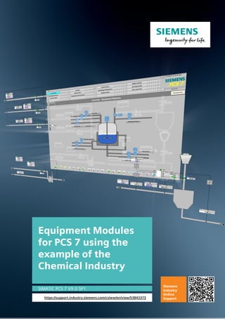
  • 1. Equipment Modules for PCS 7 using the example of the Chemical Industry SIMATIC PCS 7 V9.0 SP1 https://support.industry.siemens.com/cs/ww/en/view/53843373 Siemens Industry Online Support
  • 2. Legal information Equipment modules Entry-ID: 53843373, V5.0, 05/2019 2 © Siemens AG 2019 All rights reserved Legal information Use of application examples Application examples illustrate the solution of automation tasks through an interaction of several components in the form of text, graphics and/or software modules. The application examples are a free service by Siemens AG and/or a subsidiary of Siemens AG (“Siemens”). They are non- binding and make no claim to completeness or functionality regarding configuration and equipment. The application examples merely offer help with typical tasks; they do not constitute customer-specific solutions. You yourself are responsible for the proper and safe operation of the products in accordance with applicable regulations and must also check the function of the respective application example and customize it for your system. Siemens grants you the non-exclusive, non-sublicensable and non-transferable right to have the application examples used by technically trained personnel. Any change to the application examples is your responsibility. Sharing the application examples with third parties or copying the application examples or excerpts thereof is permitted only in combination with your own products. The application examples are not required to undergo the customary tests and quality inspections of a chargeable product; they may have functional and performance defects as well as errors. It is your responsibility to use them in such a manner that any malfunctions that may occur do not result in property damage or injury to persons. Disclaimer of liability Siemens shall not assume any liability, for any legal reason whatsoever, including, without limitation, liability for the usability, availability, completeness and freedom from defects of the application examples as well as for related information, configuration and performance data and any damage caused thereby. This shall not apply in cases of mandatory liability, for example under the German Product Liability Act, or in cases of intent, gross negligence, or culpable loss of life, bodily injury or damage to health, non-compliance with a guarantee, fraudulent non-disclosure of a defect, or culpable breach of material contractual obligations. Claims for damages arising from a breach of material contractual obligations shall however be limited to the foreseeable damage typical of the type of agreement, unless liability arises from intent or gross negligence or is based on loss of life, bodily injury or damage to health. The foregoing provisions do not imply any change in the burden of proof to your detriment. You shall indemnify Siemens against existing or future claims of third parties in this connection except where Siemens is mandatorily liable. By using the application examples you acknowledge that Siemens cannot be held liable for any damage beyond the liability provisions described. Other information Siemens reserves the right to make changes to the application examples at any time without notice. In case of discrepancies between the suggestions in the application examples and other Siemens publications such as catalogs, the content of the other documentation shall have precedence. The Siemens terms of use (https://support.industry.siemens.com) shall also apply. Security information Siemens provides products and solutions with industrial security functions that support the secure operation of plants, systems, machines and networks. In order to protect plants, systems, machines and networks against cyber threats, it is necessary to implement – and continuously maintain – a holistic, state-of-the-art industrial security concept. Siemens’ products and solutions constitute one element of such a concept. Customers are responsible for preventing unauthorized access to their plants, systems, machines and networks. Such systems, machines and components should only be connected to an enterprise network or the Internet if and to the extent such a connection is necessary and only when appropriate security measures (e.g. firewalls and/or network segmentation) are in place. For additional information on industrial security measures that may be implemented, please visit https://www.siemens.com/industrialsecurity. Siemens’ products and solutions undergo continuous development to make them more secure. Siemens strongly recommends that product updates are applied as soon as they are available and that the latest product versions are used. Use of product versions that are no longer supported, and failure to apply the latest updates may increase customer’s exposure to cyber threats. To stay informed about product updates, subscribe to the Siemens Industrial Security RSS Feed at: https://www.siemens.com/industrialsecurity.
  • 3. Table of contents Equipment modules Entry-ID: 53843373, V5.0, 05/2019 3 © Siemens AG 2019 All rights reserved Table of contents Legal information......................................................................................................... 2 1 Introduction........................................................................................................ 5 1.1 Overview............................................................................................... 5 1.2 Mode of operation ................................................................................ 6 1.3 Components used ................................................................................ 8 2 Preparation and commissioning...................................................................... 9 2.1 Preparation........................................................................................... 9 2.2 Commissioning................................................................................... 10 3 Integrating the Unit Template in the user project ........................................ 11 3.1 Preparation......................................................................................... 11 3.2 Copying templates.............................................................................. 11 3.3 Copying Equipment Module ............................................................... 12 3.4 Adapting the OS project ..................................................................... 13 4 Control Module ................................................................................................ 14 4.1 Introduction......................................................................................... 14 4.2 Best Practice Control Module Type Library........................................ 16 4.3 "ModPreCon" 4x4 multivariable controller.......................................... 17 4.3.1 Standard multivariable controller........................................................ 17 4.3.2 Predictive controller for only one controlled variable ......................... 20 4.4 "PIDCon” controller............................................................................. 23 4.4.1 Standard controller............................................................................. 23 4.4.2 Ratio controller ................................................................................... 24 4.4.3 Split range controller .......................................................................... 28 5 Equipment Modules......................................................................................... 32 5.1 "Level-Control" in process plants ....................................................... 33 5.1.1 Exact level control .............................................................................. 33 5.1.2 Buffer level control with feedforward disturbance compensation "Buffer-Control" .................................................................................. 39 5.1.3 Simulation - structure and parameterization ...................................... 48 5.1.4 Comparison of exact level control with buffer control including feedforward disturbance compensation ............................................. 52 5.2 "Split-Range-Pressure" control........................................................... 55 5.3 "Ratio-Control".................................................................................... 61 5.4 "Split-Range-Temperature" control .................................................... 71 5.5 pH value control using a standard controller...................................... 79 5.6 pH value control using predictive controller ....................................... 86 5.7 "Temperature-Flow-Cascade"............................................................ 96 5.8 Coarse-/Finestream-Control "Stream-Control”................................. 103 5.9 Gradient limits in actuators "Gradient-Limit" .................................... 110 5.9.1 Control behavior without active method........................................... 114 5.9.2 Method 1 "External Reset" ............................................................... 116 5.9.3 Method 2 "Tracking the output value if the deviation is too large". ............................................................................................... 119 5.9.4 Method 3 "Blocking the integrator"................................................... 121 5.9.5 Method 4 "Block integrator with gradient calculation". ..................... 123 5.9.6 Methods comparison........................................................................ 125 5.10 Instance-specific adaptations........................................................... 127 6 Additional information .................................................................................. 129 6.1 General Information.......................................................................... 129 6.2 Standardized plant units................................................................... 130
  • 4. Table of contents Equipment modules Entry-ID: 53843373, V5.0, 05/2019 4 © Siemens AG 2019 All rights reserved 6.3 Design and structure ........................................................................ 132 6.3.1 CFC naming convention................................................................... 132 6.3.2 Plant view ......................................................................................... 133 6.4 Controllers and control response ..................................................... 134 6.4.1 Tracking standard and cascade controllers ..................................... 134 6.4.2 Tracking ratio controllers.................................................................. 135 6.4.3 Tracking split range temperature ..................................................... 136 6.4.4 Faults and maintenance for temperature throughflow cascade....... 137 6.4.5 Faults and maintenance for ratio controllers.................................... 141 6.4.6 Faults and maintenance of split range temperature......................... 148 6.5 Block description of "pHTitrBlock".................................................... 153 6.6 Block description of "SimpHTitr"....................................................... 156 6.7 Block description of "ComStruIn" and "ComStruOut"....................... 158 7 Appendix ........................................................................................................ 160 7.1 Service and support ......................................................................... 160 7.2 Links and literature........................................................................... 161 7.3 Change documentation .................................................................... 162
  • 5. 1 Introduction Equipment modules Entry-ID: 53843373, V5.0, 05/2019 5 © Siemens AG 2019 All rights reserved 1 Introduction 1.1 Overview The standardization of automation engineering for processing plants, such as in the chemical industry, is a major challenge. Different process steps and procedures, different equipment and flexibility in the production make the task even more difficult. One approach for standardization is structuring the plant according to the physical model of ISA 106. This specifies the lower four levels, i.e. plant, unit, plant unit and control module. A plant always consists of units. The plant sections can, in turn, contain standardized plant sections that are based on equipment modules. An equipment module comprises both the physical equipment and the user program. This application example contains standardized equipment modules in the form of software typicals that are provided in SIMATIC PCS 7 as a multiproject. Using them offers the following benefits: • A reduction in the expertise necessary to develop applications • Less effort needed for configuration • Re-use of field-proven control strategies • Harmonized structures • Flexible structuring and adjustment of partial automation solutions The equipment modules offer a template that comprises the typical components of a partial automation solution, incl. open- and closed-loop control, the necessary logic and visualization. An equipment module is configured independently of the automation hardware and is a component of a pre-configured PCS 7 project including the process visualization system. Due to hardware-independent configuration and the modular structure, it is possible to integrate and use the equipment modules in PCS 7 projects in any way you like. Equipment modules are composed of control modules (CMs). Function blocks of the PCS 7 Advanced Process Library (APL) are used to create a control module.
  • 6. 1 Introduction Equipment modules Entry-ID: 53843373, V5.0, 05/2019 6 © Siemens AG 2019 All rights reserved 1.2 Mode of operation The equipment module concept provides pre-engineered and unified components for creating an automation solution, e.g. metering or temperature control. The diagram below shows the equipment modules as components of a partial automation solution as an example. Inflow of input material Pressure control Temperature control Outflow of product Stirred tank Equipment module Partial automation solution The equipment module concept provides pre-engineered and unified components for creating an automation solution, e.g. metering or temperature control. The equipment modules are implemented in the PCS 7 multiproject as follows: • One project for the automation system (AS) and one project for the operator station (OS) are contained in the component view. • A hierarchy folder has been created in the plant hierarchy for each equipment module. • The master data library contains all of the control module types in use. In the AS project, all of the open- and closed-loop control functions are implemented in the form of Continuous Function Charts (CFCs). Apart from this, the AS project contains a simulation that approximately simulates a procedure, e.g. a filling level change within an equipment module. The OS project contains visualization by means of one process picture per equipment module and shows: • Schematic representation of the equipment module • Approximately simulated process response • Relevant parameters (KPI: Key Performance Indicator) • Monitoring of control performance
  • 7. 1 Introduction Equipment modules Entry-ID: 53843373, V5.0, 05/2019 7 © Siemens AG 2019 All rights reserved The overview picture and the structure of a process picture of an equipment module are described below. For a detailed description of the core functionality of an equipment module, please refer to Chapter 5 "Equipment Modules". Visualization interface The visualization interface of the equipment modules consists of an overview picture and a process picture for each equipment module. Overview picture The overview picture contains a schematic representation in the form of a material flow diagram of the process engineering system that includes all the equipment modules in the example project. Using the pushbutton of an equipment module, you switch to the respective process picture that contains the functionality and the specific information of an equipment module. The system represents the process pictures in the form of an appropriate section of the P&ID of a system. Process picture The process picture of an equipment module consists of the following parts: • Schematic representation (P&ID) • Simulation • Faceplates for controlling the individual components (units) • Trend curve representation to visualize control response In the process picture, operators are provided with an overview of the respective equipment module and can understand the runtime response on a time basis. Delimitation The process behavior is not simulated in detail within the equipment module.
  • 8. 1 Introduction Equipment modules Entry-ID: 53843373, V5.0, 05/2019 8 © Siemens AG 2019 All rights reserved Required knowledge Basic knowledge of the following specialist fields is a prerequisite: • Configuring using SIMATIC PCS 7 CM technology and the APL • Knowledge of control technology • Basic knowledge of process technology 1.3 Components used This application example has been created with the following hardware and software components: Component Note SIMATIC PCS 7 ES/OS IPC547G W7 For the PCS 7 V9.0 SP1 example project SIMATIC PCS 7 V9.0 SP1 Part of SIMATIC PCS°7 ES/OS IPC547G W7 Advanced Process Library V9.0 SP1 Part of SIMATIC PCS°7 V9.0 SP1 S7-PLCSIM Not part of SIMATIC PCS 7 V9.0 SP1; appropriate licenses are required. CFC V9.0 SP2 Update for the part of SIMATIC PCS°7 V9.0 SP1. Under the following link you find the required Update: https://support.industry.siemens.com/cs/ww/en/view/109756832 NOTE In case of different hardware, please take heed of the minimum requirements for installing the software components. The minimum requirements can be found in the Readme of the PCS 7 under follow link: https://support.industry.siemens.com/cs/ww/en/view/109750097. This application example consists of the following components: Component Note 53843373_EquipmentModules_PROJ_PCS7V90SP1.zip Example project 53843373_EquipmentModules_DOC_PCS7V90SP1_de.pdf This document
  • 9. 2 Preparation and commissioning Equipment modules Entry-ID: 53843373, V5.0, 05/2019 9 © Siemens AG 2019 All rights reserved 2 Preparation and commissioning 2.1 Preparation The following instructions describe commissioning of the equipment modules by simulating the controller using the "S7-PLCSIM" program. If you are using a real controller, you must configure existing hardware components in the hardware settings. 1. Copy file "53843373_EquipmentModules_PROJ_PCS7V90SP1.zip" to any folder on the configuration PC and then open SIMATIC Manager. 2. Click on "File > Retrieve" on the menu bar and select file "53843373_EquipmentModules_PROJ_PCS7V90SP1.zip". Then click on "Open" to confirm. 3. Choose the folder where you want to save the project and click on "OK" to confirm. The project is retrieved. 4. Confirm the "Retrieve" dialog by clicking on the "OK" button and then click on "Yes" in the dialog to open the project. 5. Right-click on "EquipmentModules_OS > PCS7901 > WinCC Appl. > OS" and then click on the "Open object" menu command. 6. Confirm the "Configured server not available" dialog with "OK". 7. In the WinCC Explorer, open the properties of your computer and, in the opened Properties dialog, click on the "Use local computer name" button. 8. Confirm the "Change computer name" message with "OK". 9. In the WinCC Explorer, click on "File > Exit" and in the subsequent dialog select "Terminate WinCC Explorer and close project". 10. Then confirm with "OK". 11. Reopen the WinCC Explorer as described in step 5. 12. Open by double-clicking on "Variables library". 13. In the "WinCC Configuration Studio", open "Variables library > SIMATIC S7 Protocol Suite > TCP/IP" and select the menu command "System parameters". 14. In the "Unit" tab, check the "Logical device names" setting. If the "S7 PLCSIM" program is used, the device name "PLCSIM.TCPIP.12" is selected. A restart is required after a device name change. Note If the OS cannot establish a connection with the AS (grayed out module icons), select the logical device name "CP_H1_1" and restart the OS runtime.
  • 10. 2 Preparation and commissioning Equipment modules Entry-ID: 53843373, V5.0, 05/2019 10 © Siemens AG 2019 All rights reserved 2.2 Commissioning You can commission the equipment modules after starting the simulation. You can find a detailed description in Chapter 5. Starting the simulation (S7 PLCSIM) To start the simulation, proceed according to the following instructions: 1. Select "Extras > Simulate Modules" from the menu. The "S7 PLCSIM" dialog window opens. 2. In the "Open project" dialog, select "Open project from file". 3. Select file "EquipmentModules.plc" from path <project path>FunctionEMEquipmentModules.plc>. 4. In the menu, change "PLCSIM(MPI)" to "PLCSIM(TCP/IP)". 5. In the menu, select "Execute > key switch position > RUN-P". Activate OS (WinCC runtime) To activate the OS, proceed according to the following instructions: 1. Right-click on the OS and select the menu "Open object". 2. To activate the OS (WinCC Runtime), select the menu command "File > Activate" in WinCC Explorer. 3. In the "System Login" dialog, enter user name "Equipment" as the "Login" and "Modules" as the password and then click on "OK" to confirm. 4. In the picture area, select an equipment module; in this example, it is "temperature flow cascade".
  • 11. 3 Integrating the Equipment Module in the user project Equipment modules Entry-ID: 53843373, V5.0, 05/2019 11 © Siemens AG 2019 All rights reserved 3 Integrating the Equipment Module in the user project 3.1 Preparation 1. Copy the file "53843373_EquipmentModules_PROJ_PCS7V90SP1.zip" to the configuration PC and then open the SIMATIC Manager. 2. Click on "File > Retrieve" in the menu bar and select the file "53843373_EquipmentModules_PROJ_PCS7V90SP1.zip". Then confirm by clicking on "Open". 3. Select the folder in which the project will be saved and confirm with the "OK" button. The project will be extracted. 4. In the "Retrieve" dialog, click on the "OK" button and then click on "Yes" in the dialog to open the project. 5. Switch to the "Plant view". 6. At the same time, open the project in which the Equipment Modules is to be integrated. 3.2 Copying templates Note If you have already worked with CMTs in your existing project, then check that they are identical before skipping to the following steps, since this can lead to errors in your existing project or in the Unit Template you want to integrate. 1. Switch to the plant view. 2. Copy the "BPCM" and "pH" folder containing the CMTs from the master data library into the target project. 3. Copy the Enumerations from the master data library into the target project.
  • 12. 3 Integrating the Equipment Module in the user project Equipment modules Entry-ID: 53843373, V5.0, 05/2019 12 © Siemens AG 2019 All rights reserved 3.3 Copying Equipment Module 1. Copy the hierarchy folder with the desired Equipment Module from the AS project of the Equipment Module to the plant view of the target project. 2. Copy the corresponding process screens from the OS project of the Equipment Module to the plant view of the target project as well. If you wish, you can also copy the pictures "Help" and "Overview". Note When copying the process screens, make sure that you copy the pictures to the hierarchy level of the target project, which is configured as an OS area.
  • 13. 3 Integrating the Equipment Module in the user project Equipment modules Entry-ID: 53843373, V5.0, 05/2019 13 © Siemens AG 2019 All rights reserved 3.4 Adapting the OS project In order to facilitate the changing of colors in the process screen from a central point, a central color palette was created in the OS project. To display these colors in the process screen of your own project, you must import the relevant color palette. 1. Select the "OS" in WinCC Explorer and choose "Object properties..." in the shortcut menu. 2. Choose the "User Interface and Design" tab and click the "Edit" button. 3. Import the palette into your own project by means of the "Overwrite" option. The color palette is located in the project folder of the Unit Template at the path: "<Project path>EquipmentModulesEM_OSwincprojOSGraCS UnitTemplate.xml>". All existing colors will be replaced. Note Please note that all colors are always used when exporting/importing color palettes. It is not possible to export partial color tables. If you have created your own color tables in your project, you can also export them and use an editor to merge the tables in the XML file. Otherwise you can create a new color table in your project and configure the colors individually. Make sure, too, that the color index does not change, otherwise you will have to adjust the color settings of the objects in the process screen. Of course it is up to you to change the colors according to your requirements.
  • 14. 4 Control Module Equipment modules Entry-ID: 53843373, V5.0, 05/2019 14 © Siemens AG 2019 All rights reserved 4 Control Module 4.1 Introduction A control module is used to control individual pieces of equipment, like motors, valves, and controllers, for example. The necessary blocks for carrying out this job, e.g. controlling a valve, are combined in a control module (CM). If a control module is used several times in the project, e.g. with different characteristics, you create a control module type (CMT) from it in PCS 7 and store it in the master data library. You can use this CMT in a flexible way anywhere in the project as an instance with different characteristics (variants). Using the technology allows to test automation projects using the program logic even if you do not have the real hardware. Note The application example "Control Module (CM) Technology - Efficient Engineering with SIMATIC PCS 7" gives you a general overview of how to create, extend, and instantiate a CMT. The application example is available at the following link: https://support.industry.siemens.com/cs/ww/en/view/109475748 Master data library This chapter gives you detailed information about the structure and mode of operation of the CMTs on which the equipment modules are based. All of the CMTs are stored in the "EquipmentModules_Lib" master data library of the PCS 7 projects. The CMTs are sub-divided as follows: • Multivariable controller in the "ModPreCon" folder • Analog measured value display in the "MonAn" folder • Digital measured value display in the "MonDi" folder • Motor in the "Mot" folder • Analog value input in the "OpAn" folder • Digital value input in the "OpDi" folder • Controller in the "PIDCon" folder • Valve in the "Vlv" folder
  • 15. 4 Control Module Equipment modules Entry-ID: 53843373, V5.0, 05/2019 15 © Siemens AG 2019 All rights reserved CMTs are of compact structure, i.e. all the relevant blocks are at defined locations. For example, channel blocks are always in chart partition B of a CFC. Note Folder "pH" contains the source files of the pH simulation and the conversion block from pH value to concentration difference. The functions and structure of the block are described in Section 6.5. Selecting a variant A variant and the options that are necessary for solving an automation task are determined in the instance. 1. To do this, the system displays the technological I/Os in the CFC, 2. the available variants are displayed via the shortcut menu and 3. the functionality that is necessary for the automation task is determined by selecting the options.
  • 16. 4 Control Module Equipment modules Entry-ID: 53843373, V5.0, 05/2019 16 © Siemens AG 2019 All rights reserved 4.2 Best Practice Control Module Type Library The Best Practice Control Modules (BPCM) in the form of a Type Library are available for SIMATIC PCS 7 as a master data library and contain typical, pre- projected and tested CMT. The BPCM are created with CM technology and enable more efficient engineering through standardized program components. The following benefits are achieved by using the BPCM Type Library: • Extensive library for different applications and industries • Reduction of the project planning effort • Reduced maintenance • Standardized structures The BPCM Type Library offers typical components as a template for building automation solutions. The CMT of the BPCM Type Library contain all necessary function and channel blocks and can be adapted to the project-specific conditions by instantiation. The BPCM's are based on the SIMATIC PCS 7 Advanced Process Library (APL) and Industry Library (IL), are hardware-independent, pre-configured and modular. The library "109475748_BPCM_LIB_PCS7_V90SP1.zip" provides the following CMT groups: • MonAn: Analog measured value display • MonDi: Digital measured value display (binary signal) • OpAn: Setting a analog value by the operator • OpDi: Setting a binary value by the operator • PIDConL Controller for standard and cascade control loops • Mot: Motor control with simple speed control • MotSpdC: Motor control with variable speed control • Vlv: Valve actuation with two defined positions • VlvAn: Valve control with analog control valve Note The BPCM library uses the name of the central technology block of the APL. Note A detailed description of each CMT with function description, supported variants and control elements you can find in the application example "Control Module (CM) Technology - Efficient Engineering with SIMATIC PCS 7" under the link: https://support.industry.siemens.com/cs/ww/en/view/109475748
  • 17. 4 Control Module Equipment modules Entry-ID: 53843373, V5.0, 05/2019 17 © Siemens AG 2019 All rights reserved 4.3 "ModPreCon" 4x4 multivariable controller The multivariable controller CMTs contains controller blocks, a control performance monitoring system, interface blocks (slave/actuator) and the link to sequential function charts. The CMTs are pre-configured for different areas of application. Using options, you select or deselect blocks, e.g. the channel blocks, that are needed for the application. The following CMTs are available: • "ModPreCon" for multivariable control using up to four controlled variables • "ModPreCon4Valve" for one controlled variable with several disturbance variables 4.3.1 Standard multivariable controller CMT "ModPreCon" is used for multivariable controllers. Unlike the "PIDCon", multivariable controllers master up to four manipulated and controlled variables that are interacting with each other. The instance receives the process variables with standardization from the "MonAn" process tags via "from_Indicate_x". The number of controlled variables is determined by activating options "Ctrl_PV_3” and "Ctrl_PV_4”. It is not possible to deselect "Ctrl_PV_1" and "Ctrl_PV_2" and they correspond to the smallest configuration. Each "Ctrl_PV_x" option contains the monitoring of control performance, interface blocks for the process variable ("MonAn") and controller process tag as well as the setpoint tolerance limits and manipulated variable tracking. Due to the complex control tasks (affected by up to four manipulated variables) and the required computing power, the multivariable controller is used by preference for slow control loops. Examples of multivariable controllers include: • Control of drying processes (product quality) • Control of distillation columns (rectification) Structure Chart partion A Sheet 1 Sheet 2 Sheet 3 Sheet 5 Sheet 4 Sheet 6
  • 18. 4 Control Module Equipment modules Entry-ID: 53843373, V5.0, 05/2019 18 © Siemens AG 2019 All rights reserved Chart partition A The following blocks are located on sheet 1: • MPC ("ModPreCon"): Multivariable controller • AutoExcitation ("AutoExci"): Process excitation signals for the MPC (during commissioning of the controller only) Blocks for static operating point optimization of controlled variables of the MPC controller are located on sheet 2: • SP1OptHiLim ("Add04"): Adaptation of the upper tolerance limit for SP1 • SP1OptLoLim ("Add04"): Adaptation of the lower tolerance limit for SP1 • SP2OptHiLim ("Add04"): Adaptation of the upper tolerance limit for SP2 • SP2OptLoLim ("Add04"): Adaptation of the lower tolerance limit for SP2 • SP3OptHiLim ("Add04"): Adaptation of the upper tolerance limit for SP3 • SP3OptLoLim ("Add04"): Adaptation of the lower tolerance limit for SP3 • SP4OptHiLim ("Add04"): Adaptation of the upper tolerance limit for SP4 • SP4OptLoLim ("Add04"): Adaptation of the lower tolerance limit for SP4 Note In the case of operating point optimization, you do not specify an exact setpoint (e.g. SP1) for a controlled variable; rather, a tolerance range is specified. The associated command value (CV1) may be within this tolerance. Due to this tolerance definition, the controller works more flexibly and more economically, since it does not have to control continuously to a fixed value. The following blocks are located on sheet 3: • MV1_TrkOn ("Or04"): Forced manipulated variable (MV1) for the MPC controller in the case of a hardware fault (CV_Bad) or if cascade switching is interrupted between the MV1 PID controller and the slave controller • MV2_TrkOn ("Or04"): Forced manipulated variable (MV2) for the MPC controller in the case of a hardware fault (CV_Bad) or if cascade switching is interrupted between the MV2 PID controller and the MV2 slave controller • MV3_TrkOn ("Or04"): Forced manipulated variable (MV3) for the MPC controller in the case of a hardware fault (CV_Bad) or if cascade switching is interrupted between the MV3 PID controller and the MV3 slave controller • MV4_TrkOn ("Or04"): Forced manipulated variable (MV3) for the MPC controller in the case of a hardware fault (CV_Bad) or if cascade switching is interrupted between the MV4 PID controller and the MV4 slave controller The blocks below for monitoring and display of the control performance and the control deviation are located on sheet 4: • Suppr_CPM_Calc_1 ("Or04"): Suppression of CPI calculation and message if message suppression was caused at an "MPC_CPM_x" (CPI_SuRoot = 1) or a warning is active due to low control performance (CPI_WL_Act = 1). • Suppr_CPM_Calc_2 ("Or04"): Suppression of CPI calculation and message if message suppression was caused at an "MPC_CPM_x" (CPI_SuRoot = 1) or a warning is active due to low control performance (CPI_WL_Act = 1).
  • 19. 4 Control Module Equipment modules Entry-ID: 53843373, V5.0, 05/2019 19 © Siemens AG 2019 All rights reserved • Suppr_CPM_Calc_3 ("Or04"): Suppression of CPI calculation and message if message suppression was caused at an "MPC_CPM_x" (CPI_SuRoot = 1) or a warning is active due to low control performance (CPI_WL_Act = 1). • Suppr_CPM_Calc_4 ("Or04"): Suppression of CPI calculation and message if message suppression was caused at an "MPC_CPM_x" (CPI_SuRoot = 1) or a warning is active due to low control performance (CPI_WL_Act = 1). • MPC_CPM_1 ("ConPerMon"): Block for permanent monitoring of control performance (SP1Out, MV1 and CV1Out) • MPC_CPM_2 ("ConPerMon"): Block for permanent monitoring of control performance (SP2Out, MV2 and CV2Out) • MPC_CPM_3 ("ConPerMon"): Block for permanent monitoring of control performance (SP3Out, MV3 and CV3Out) • MPC_CPM_4 ("ConPerMon"): Block for permanent monitoring of control performance (SP4Out, MV4 and CV4Out) • QI_1 ("MonAnL"): Display and limit monitoring of the average value of control deviation for the TimeWindow specified in "MPC_CPM_1" • QI_2 ("MonAnL"): Display and limit monitoring of the average value of control deviation for the TimeWindow specified in "MPC_CPM_2" • QI_3 ("MonAnL"): Display and limit monitoring of the average value of control deviation for the TimeWindow specified in "MPC_CPM_3" • QI_4 ("MonAnL"): Display and limit monitoring of the average value of control deviation for the TimeWindow specified in "MPC_CPM_4" The following blocks are located on sheet 5: • from_Indicate_1 ("ComStruOut"): Reception of signals (measured value, unit, scaling and messages) of the first process value to be controlled • from_Indicate_2 ("ComStruOut"): Reception of signals (measured value, unit, scaling and messages) of the second process value to be controlled • from_Indicate_3 ("ComStruOut"): Reception of signals (measured value, unit, scaling and messages) of the third process value to be controlled • from_Indicate_4 ("ComStruOut"): Reception of signals (measured value, unit, scaling and messages) of the fourth process value to be controlled • SPLim_1 ("StruScIn"): Upper and lower setpoint limit of the first process value • SPLim_2 ("StruScIn"): Upper and lower setpoint limit of the second process value • SPLim_3 ("StruScIn"): Upper and lower setpoint limit of the third process value • SPLim_4 ("StruScIn"): Upper and lower setpoint limit of the fourth process value • CSF ("Or04"): Formation of an OR output signal of the hardware faults of the channel blocks of the process values for tracking the respective controller • OosAct ("Or04"): Formation of an OR output signal of the "OosAct" message of the channel blocks (field device is being maintained) of the controlled variables for the MPC
  • 20. 4 Control Module Equipment modules Entry-ID: 53843373, V5.0, 05/2019 20 © Siemens AG 2019 All rights reserved The link blocks below, which are used for rapid engineering, are located on sheet 6: • from_CTRL_1 ("ComStruOu"): Reception of control commands of the lower level PID controller for the MPC controller parameters ("MV1ManHiLim", "MV1ManLoLim", and "MV1Trk") and the "MV1_TrkOn" block. • to_CTRL_1 ("ComStruIn"): Output of the manipulated variable as a setpoint to the lower-level PID controller. • from_CTRL_2 ("ComStruOu"): Reception of control commands of the lower level PID controller for the MPC controller parameters ("MV2ManHiLim", "MV2ManLoLim", and "MV2Trk") and the "MV2_TrkOn" block. • to_CTRL_2 ("ComStruIn"): Output of the manipulated variable as a setpoint to the lower-level PID controller. • from_CTRL_3 ("ComStruOu"): Reception of control commands of the lower level PID controller for the MPC controller parameters ("MV3ManHiLim", "MV3ManLoLim", and "MV3Trk") and the "MV3_TrkOn" block. • to_CTRL_3 ("ComStruIn"): Output of the manipulated variable as a setpoint to the lower-level PID controller. • from_CTRL_4 ("ComStruOu"): Reception of control commands of the lower level PID controller for the MPC controller parameters ("MV4ManHiLim", "MV4ManLoLim", and "MV4Trk") and the "MV1_TrkOn" block. • to_CTRL_4 ("ComStruIn"): Output of the manipulated variable as a setpoint to the lower-level PID controller. Note The process value is made available to the MPC by linking the MonAn control module ("to_Indicate" block) with the "from_Indicate_x" block. 4.3.2 Predictive controller for only one controlled variable The "ModPreCon4Valve" CMT is used for fixed value controllers where the controlled variable is affected by one or more measurable disturbance variables, e.g. pH value control. The MPC gets the units and standardization automatically from the connected interface blocks, from the controlled and manipulated variables, and from at least one disturbance variable. Note The number of disturbance variables is determined by activating option '"Opt_DVx" and interconnecting the respective process value. The disturbance variables are interconnected with the following MPC inputs: • 1st disturbance variable at the DV1 input of the MPC (activated as standard) • 2nd disturbance variable at the MV2Trk input of the MPC (optional) • 3rd disturbance variable at the MV3Trk input of the MPC (optional) • 4th disturbance variable at the MV4Trk input of the MPC (optional)
  • 21. 4 Control Module Equipment modules Entry-ID: 53843373, V5.0, 05/2019 21 © Siemens AG 2019 All rights reserved Structure Chart partion „A“ Sheet 1 Sheet 2 Sheet 3 Sheet 5 Sheet 4 Sheet 6 Chart partition A The following blocks are located on sheet 1: • MPC ("ModPreCon"): Multivariable controller • AutoExcitation ("AutoExci"): Process excitation signals for the predictive MPC (during commissioning of the controller only) Blocks for static operating point optimization of the controlled variable of the MPC controller are located on sheet 2: • SP1OptHiLim ("Add04"): Adaptation of the upper tolerance limit for SP1 • SP1OptLoLim ("Add04"): Adaptation of the lower tolerance limit for SP1 Note In the case of operating point optimization, you do not specify an exact setpoint (e.g. SP1) for a controlled variable; rather, a tolerance range is specified. The associated command value (CV1) may be within this tolerance. Due to this tolerance definition, the controller works more flexibly and more economically, since it does not control continuously to a fixed value. The blocks below for monitoring and display of the control performance and the control deviation are located on sheet 4: • MPC_CPM ("ConPerMon"): Block for permanent monitoring of control performance (SP1Out, MV1 and CV1Out) • QI ("MonAnL"): Display and limit monitoring of the average value of control deviation for the TimeWindow specified in "MPC_CPM"
  • 22. 4 Control Module Equipment modules Entry-ID: 53843373, V5.0, 05/2019 22 © Siemens AG 2019 All rights reserved The following blocks are located on sheet 5: • from_CV ("ComStruOut"): Receiving of signals (measured value, unit, scaling and messages) of the controlled variable • CV_Lim ("StruScIn"): Upper and lower setpoint limit of the controlled variable • from_DV1 ("ComStruOut"): Receiving of signals (measured value, CSF-signal and unit) of the first disturbance variable • from_DV2 ("ComStruOut"): Receiving of signals (measured value, CSF-signal and unit) of the second disturbance variable • from_DV3 ("ComStruOut"): Reception of signals (measured value, CSF-signal and unit) of the third disturbance variable • from_DV4 ("ComStruOut"): Reception of signals (measured value, CSF-signal and unit) of the fourth disturbance variable • CSF ("Or04"): Formation of an OR output signal of the hardware faults of the controlled variable channel blocks and the control valve for tracking the manipulated variable • OosAct ("Or04"): Formation of an OR output signal of the "OosAct" message of the channel blocks (field device is being maintained) of the controlled variables and the control valve for the MPC Note The process values of the controlled variable and the disturbance variables are made available to the MPC by linking the MonAn control modules ("to_Indicate" block) with the "from_CV", "from_DVx" block. The link blocks below, used for rapid engineering, are located on sheet 6. • to_Actor ("ComStruIn"): Transfer of the manipulated variable (MV1), and the locking status (OosAct) to the actuator. • from_Actor ("ComStruOu"): Reception of signals and standardization and unit of the actuator for the MPC (CSF, OosAct, ScaleOut, Unit). • MV1_Scale ("StruScIn"): Upper and lower manipulated variable limit for limiting the manipulated variable in the controller in manual and automatic modes.
  • 23. 4 Control Module Equipment modules Entry-ID: 53843373, V5.0, 05/2019 23 © Siemens AG 2019 All rights reserved 4.4 "PIDCon” controller The controller CMTs contain controller blocks, additional monitoring and interlock functions, interface blocks (master/actuator), and a link to sequential function charts. The CMTs are pre-configured for different areas of application. The following controller CMTs are available: • "PIDCon” for standard PID controllers • "PIDConRatio" for ratio controllers • "PIDConSplitRange” for controllers with one manipulated variable and two actuators 4.4.1 Standard controller The "PIDCon” CMT is used for fixed-value and cascade controllers and is a component from the Best Practice Control Modules (BPCM). The detailed description of the you can find in the application example "Control Module (CM) Technology - Efficient Engineering with SIMATIC PCS 7" under the link: https://support.industry.siemens.com/cs/ww/en/view/109475748 Examples of standard controllers include: • Fill level controller with inflow and outflow • Temperature control
  • 24. 4 Control Module Equipment modules Entry-ID: 53843373, V5.0, 05/2019 24 © Siemens AG 2019 All rights reserved 4.4.2 Ratio controller The "PIDConRatio” control module type is used for ratio controllers. Ratio controllers are composed of a flow controller (for the main component) and a flow controller for each additional component. The instance of "PIDConRatio” is used for the component that is to be added in a defined ratio, e.g. the blended component. Note In "Plant View”, you activate master/slave operation by selecting "Opt_IF_Master”. After activation, the "to_Master” and "from_Master” link blocks are available. Using variants, the corresponding channel block is selected or deselected based on measured value transfer. In addition, it is possible to use options to activate further functions without configuration at the CMT instance. Variants and options are listed and described below. Variant 1: Controller for analog measurement and manipulated variable (4-20 mA) Variant 1 is activated by selecting functions PV_In and Opt_PV_Scale at the instance. Variant 2: Controller for thermocouples This variant is used for thermocouples that are connected to an analog input module for temperature measurement. Variant 2 is activated by selecting function PV_TE_In at the instance. Note Scaling on the channel block has already been preset for the range 0 to 1. You must carry out process value scaling at input "NormPV” of display block "C”. Variant 3: Controller for digital measurement (field bus) This variant is used if you are using measuring devices with Profibus PA or Fieldbus Foundation (FF). Variant 3 is activated by selecting functions PV_Fb_In and Opt_PV_Scale on the instance. Variant 4: Controller for software signal Variant 4 is the default setting without additional functions activated at the instance. In this variant, the process value is obtained by direct CFC connection from existing process tags. Using the optional DeltaCalc function, it is possible to apply difference measurement for the controlled variable. Optional functions for all variants: • PV_Scale#: Standardization of the process value including the channel block • CPM: Monitoring of the control quality • IF_Master#: Connection to a master controller (cascade) • PV_DeltaCalc#: Differentiation • Interlock: Interlocking block
  • 25. 4 Control Module Equipment modules Entry-ID: 53843373, V5.0, 05/2019 25 © Siemens AG 2019 All rights reserved The figure below lists the available options. x = Selecting a variant o = Selectable functions PIDConRatio (CMT Master Data Library) PV_Scale# CPM IF_Master# PV_DeltaCálc Intlock PV_In PV_Fb_In PV_TE_In Variants Function Channel block Description PIDConRatio_Std x o o o x Standard display (analog) PIDConRatio_TE o o o o x Measured value display for thermocouples PIDConRatio_Fb x o o o x Measured value display fieldbus PIDConRatio_SW o o o o o Program logic without channel blocks Examples of ratio controllers include: • Blending control of liquids or gases with a defined mixing ratio • Air feed in a defined ratio to fuel gas feed for gas burners NOTICE When using the Plant Automation Accelerator (PAA) V2.1, the variant "PV_Scale#" should not be used. The scaling is set in PAA at the respective signal and adopted by the appropriate "Scale" input when exporting to SIMATIC PCS 7. Note In "plant view", you activate master/slave operation by selecting "IF_Master#". After activation, the "to_Master" and "from_Master" link blocks are available. Structure Chart partion „B“ Chart partion „A“ Sheet 1 Sheet 2 Sheet 3 Sheet 1 Sheet 2 Sheet 3 Sheet 4 Sheet 5 Sheet 6
  • 26. 4 Control Module Equipment modules Entry-ID: 53843373, V5.0, 05/2019 26 © Siemens AG 2019 All rights reserved Chart partition "A" The following blocks are located on sheet 1: • PV_Scale: Standardization of the process value for a channel block and measured value display • PV_Unit: Standardization of the unit for a channel block and displaying measured values • C ("PIDConL"): PID controller • CPM ("ConPerMon"): Block for permanent monitoring of control quality The outputs, operating mode, setpoint, actual value and manipulated variable of the PID controller are interconnected with the CPM block The following blocks are located on sheet 2: • AIF_SFC ("ConnPID"): A free block for SFC linking (not a component of the APL or the standard library) • Logic blocks for selecting the operating mode and for interlocking – SP_LiOp ("Or04"): Setpoint source internal/external – SP_IntLi ("Or04"): Internal setpoint via interconnection – MV_Forced ("SelA02In"): Forced manipulated variable with selection ("In1" undefined, "In2" SFC link) – MV_ForOn ("Or04"): Activates forced manipulated variable "In2" (MV_Forced) on the PID controller – ManModOpLi ("Or04"): Formation of an OR output signal from field device in maintenance (channel blocks PV and MV) and invalid process value (channel block PV in chart partition "B", Sheet 1.) – ModLiOp ("Or04"): Operating mode selection between operator and interconnection or SFC – ManModLi ("Or04"): Manual mode via interconnection or SFC (controlled via ModLiOp = 1) Using the SFC link, data that is relevant to production is transferred to the PID controlling via the logic blocks. In addition, channel blocks and the interlocking block (chart partition "A", Sheet 3) affect the output signals of the logic blocks. Sheet 3 contains the "Intlock" interlocking module, which combines signals for standardized interlocking with the option of displaying them on the OS. The link blocks below, used for rapid engineering, are located on sheet 6. • to_Actor_Slave ("ComStruIn"): Transfer of the manipulated variable (MV), setpoint value (SP), process value (PV), and the locking status to the actuator or slave (slave in the case of cascade control) • from_Actor_Slave ("ComStruOu"): Reception of the actuating signal feedback (Rbk), the message with invalid process values, and field device maintenance of channel blocks MV and Rbk, of the out unit and scaling of the actuating display and travel range (ScaleOut) of the actuator or slave (slave in the case of cascade control) • to_Master ("ComStruIn"): The communication block forms a structure consisting of outputs (setpoint, block is "out of service" message, message for cascade switching, process value), of the PID controller, of the CSF block (message of the channel blocks in the case of an invalid process value), and of channel blocks PV and MV (unit and scaling of the process value). • from_Master ("ComStruOu"): The communication block receives from the controller process tag of the main component the signals of the CSF block and the setpoint of the PID controller that are relevant to interlocking.
  • 27. 4 Control Module Equipment modules Entry-ID: 53843373, V5.0, 05/2019 27 © Siemens AG 2019 All rights reserved • Ratio ("Ratio"): The block calculates the setpoint of the slave controller from the setpoint of the master PID controller and the specified ratio. Chart partition "B" The channel blocks are located on sheet 1: • PV ("Pcs7AnIn"): Channel block for signal processing of an analog measured value, e.g. 0/4 to 20mA • PV_TE ("Pcs7AnIn"): Channel block for signal processing of a resistance thermometer • PV_FB ("FBAnIn"): Channel block for signal processing of a digitized process value (PA or FF processing unit) The modules for the difference display are located on sheet 2: • PV_DeltaCalc ("Sub02"): Formation of a difference value from two process values, e.g. differential pressure • FromDeltaIn1: Input 1 for the difference value • FromDeltaIn2: Input 2 for the difference value • PV_IN ("Add08"): Merging the "PV_In" signals (analog process value) • CSF ("Or04"): Grouping of the "Bad" signals (invalid process value) and reporting to the motor block and the Permit group block • OosAct ("Or04"): Grouping of the "OosAct" signals (device being maintained) and reporting to the motor block Note If a thermocouple is used, you must carry out scaling at channel block "PV_TE" measured value display in addition to scaling at block PV_Scale (process value scaling). NOTICE The channel block for the thermocouple has already been preset for the range 0.0 to 1.0. On sheet 2, the system additionally acquires the messages of the valve process tag channel block at blocks CSF and OosAct and transfers them to the controller. In the case of a positive "OosAct" signal, the controller switches to manual mode.
  • 28. 4 Control Module Equipment modules Entry-ID: 53843373, V5.0, 05/2019 28 © Siemens AG 2019 All rights reserved 4.4.3 Split range controller The "PIDConSplitRange” control module type is used for controllers where one manipulated variable controls several actuators (with a limited effective range and possibly the opposite direction of control action), i.e. the manipulated variable is split to several actuators. Note In "Plant View”, you activate master/slave operation by selecting "Opt_IF_Master”. After activation, the "to_Master” and "from_Master” link blocks are available. Using variants, the corresponding channel block is selected or deselected based on measured value transfer. In addition, it is possible to use options to activate further functions without configuration at the CMT instance. Variants and options are listed and described below. Variant 1: Controller for analog measurement and manipulated variable (4-20 mA) Variant 1 is activated by selecting functions PV_In and Opt_PV_Scale at the instance. Variant 2: Controller for thermocouples This variant is used for thermocouples that are connected to an analog input module for temperature measurement. Variant 2 is activated by selecting function PV_TE_In at the instance. Note Scaling on the channel block has already been preset for the range 0 to 1. You must carry out process value scaling at input "NormPV” of display block "C”. Variant 3: Controller for digital measurement (field bus) This variant is used if you are using measuring devices with Profibus PA or Fieldbus Foundation (FF). Variant 3 is activated by selecting functions PV_Fb_In and Opt_PV_Scale on the instance. Variant 4: Controller for software signal Variant 4 is the default setting without additional functions activated at the instance. In this variant, the process value is obtained by direct CFC connection from existing process tags. Using the optional DeltaCalc function, it is possible to apply difference measurement for the controlled variable. Optional functions for all variants: • PV_Scale#: Standardization of the process value including the channel block • CPM: Monitoring of the control quality • IF_Master#: Connection to a master controller (cascade) • PV_DeltaCalc#: Differentiation • Interlock: Interlocking block
  • 29. 4 Control Module Equipment modules Entry-ID: 53843373, V5.0, 05/2019 29 © Siemens AG 2019 All rights reserved The figure below lists the available options. x = Selecting a variant o = Selectable functions PIDConSplitRange (CMT Master Data library) PV_Scale# CPM IF_Master# PV_DeltaCalc# Intlock PV_In PV_Fb_In PV_TE_In Variants Function Channel block Description PIDConSplitRange_Std x o o o x Standard display (analog) PIDConSplitRange_TE o o o o x Measured value display for thermocouples PIDConSplitRange_Fb x o o o x Measured value display fieldbus PIDConSplitRange_SW o o o o o Program logic without channel blocks Examples of split-range controllers with opposite direction of control action include: • Temperature controllers with separate actuators for heating and cooling, e.g. valves for heating steam and cooling water, or electric heating and fan cooling. • Pressure control with separate valves for gas feed and purge Moreover, there are split range applications with several actuators with the same direction of action (that individually would not be strong enough), e.g. • Oxygen control in bio fermenters via air feed and stirrer speed. • Oxygen control in wastewater treatment plants via several compressors. Structure Chart partition „B“ Chart partition „A“ Sheet 1 Sheet 2 Sheet 3 Sheet 1 Sheet 2 Sheet 3 Sheet 4 Sheet 5 Sheet 6 The control module type is preconfigured for the following setpoint range: • Manipulated variable 0 to 100 (from the controller) • Manipulated variable 50 to 100 corresponds to travel range 0 to 100 with actuator 1 • Manipulated variable 50 corresponds to the neutral position, i.e. both actuators are closed • Travel range 0 to 50 corresponds to travel range 100 to 0 with actuator 2
  • 30. 4 Control Module Equipment modules Entry-ID: 53843373, V5.0, 05/2019 30 © Siemens AG 2019 All rights reserved Chart partition "A" The following blocks are located on sheet 1: • PV_Scale: Standardization of the process value for a channel block and measured value display • PV_Unit: Standardization of the unit for a channel block and displaying measured values • C ("PIDConL"): PID controller • CPM ("ConPerMon"): Block for permanent monitoring of control quality The outputs, operating mode, setpoint, actual value and manipulated variable of the PID controller are interconnected with the CPM block The following blocks are located on sheet 2: • AIF_SFC ("ConnPID"): A free block for SFC linking (not a component of the APL or the standard library) • Logic blocks for selecting the operating mode and for interlocking – SP_LiOp ("Or04"): Setpoint source internal/external – SP_IntLi ("Or04"): Internal setpoint via interconnection – MV_Forced ("SelA02In"): Forced manipulated variable with selection ("In1" undefined, "In2" SFC link) – MV_ForOn ("Or04"): Activates forced manipulated variable "In2" (MV_Forced) on the PID controller – ManModOpLi ("Or04"): Formation of an OR output signal from field device in maintenance (channel blocks PV and MV) and invalid process value (channel block PV in chart partition "B", Sheet 1.) – ModLiOp ("Or04"): Operating mode selection between operator and interconnection or SFC – ManModLi ("Or04"): Manual mode via interconnection or SFC (controlled via ModLiOp = 1) Using the SFC link, data that is relevant to production is transferred to the PID controlling via the logic blocks. In addition, channel blocks and the interlocking block (chart partition "A", Sheet 3) affect the output signals of the logic blocks. Sheet 3 contains the "Intlock" interlocking module, which combines signals for standardized interlocking with the option of displaying them on the OS. The link blocks below, used for rapid engineering, are located on sheet 6. • to_Actor_Slave ("ComStruIn"): Transfer of the manipulated variable (MV), setpoint value (SP), process value (PV), and the locking status to the actuator or slave (slave in the case of cascade control) • from_Actor_Slave ("ComStruOu"): Reception of the actuating signal feedback (Rbk), the message with invalid process values, and field device maintenance of channel blocks MV and Rbk, of the out unit and scaling of the actuating display and travel range (ScaleOut) of the actuator or slave (slave in the case of cascade control) • to_Master ("ComStruIn"): The communication block forms a structure consisting of outputs (setpoint, block is "out of service" message, message for cascade switching, process value), of the PID controller, of the CSF block (message of the channel blocks in the case of an invalid process value), and of channel blocks PV and MV (unit and scaling of the process value). • from_Master ("ComStruOu"): The communication block receives from the controller process tag of the main component the signals of the CSF block and the setpoint of the PID controller that are relevant to interlocking.
  • 31. 4 Control Module Equipment modules Entry-ID: 53843373, V5.0, 05/2019 31 © Siemens AG 2019 All rights reserved • SplitRange ("SplRange"): block to split the manipulated variable MV from the PID controller. The segmentation is based on the set parameters. • to_Actor_Slave2 ("ComStruIn"): Transfer of the manipulated variable (MV), setpoint value (SP), process value (PV), and the locking status to the actuator or slave (slave in the case of cascade control) • from_Actor_Slave2 ("ComStruOu"): Reception of the actuating signal feedback (Rbk), the message with invalid process values, and field device maintenance of channel blocks MV and Rbk, of the out unit and scaling of the actuating display and travel range (ScaleOut) of the actuator or slave (slave in the case of cascade control) • SplitRangeCut ("Or04"): Grouping of the disconnect signals from the cascaded valves to the controller. Chart partition "B" The channel blocks are located on sheet 1: • PV ("Pcs7AnIn"): Channel block for signal processing of an analog measured value, e.g. 0/4 to 20mA • PV_TE ("Pcs7AnIn"): Channel block for signal processing of a resistance thermometer • PV_FB ("FBAnIn"): Channel block for signal processing of a digitized process value (PA or FF processing unit) The modules for the difference display are located on sheet 2: • PV_DeltaCalc ("Sub02"): Formation of a difference value from two process values, e.g. differential pressure • FromDeltaIn1: Input 1 for the difference value • FromDeltaIn2: Input 2 for the difference value • PV_IN ("Add08"): Merging the "PV_In" signals (analog process value) • CSF ("Or04"): Grouping of the "Bad" signals (invalid process value) and reporting to the motor block and the Permit group block • OosAct ("Or04"): Grouping of the "OosAct" signals (device being maintained) and reporting to the motor block Note If a thermocouple is used, you must carry out scaling at channel block "PV_TE" measured value display in addition to scaling at block PV_Scale (process value scaling). NOTICE The channel block for the thermocouple has already been preset for the range 0.0 to 1.0. On sheet 2, the system additionally acquires the messages of the valve process tag channel block at blocks CSF and OosAct and transfers them to the controller. In the case of a positive "OosAct" signal, the controller switches to manual mode.
  • 32. 5 Equipment Modules Equipment modules Entry-ID: 53843373, V5.0, 05/2019 32 © Siemens AG 2019 All rights reserved 5 Equipment Modules In this chapter, you will find all the relevant information for each equipment module including specific properties. The structure and basic functionality of the control module types that are used are described in Chapter 4 "Control Module". The following equipment modules are described below: • "Level-control" • Buffer level control with feedforward disturbance compensation "Buffer-Control" • "Split-Range-Pressure" control • "Ratio-Control" • "Split-Range-Temperature" control • pH value control using the "pH-Control-Std" standard controller • pH value control using the "pH-Control-MPC" model predictive controller • Temperature cascade control via slave flow control loop "Temperature-Flow- Cascade" • Coarse-/Finestream control using the "Stream-Control” • Gradient limits in actuators "Gradient-Limit" Note Below, we will use the designations CM for control module and CMT for control module type.
  • 33. 5 Equipment Modules Equipment modules Entry-ID: 53843373, V5.0, 05/2019 33 © Siemens AG 2019 All rights reserved 5.1 "Level-Control" in process plants Introduction Depending on the tasks that a container (e.g. vessel, tank, reactor) has to fulfill in a process plant, there are different objectives for a level controller. The two following control strategies are the most common in process industry: 1. Keeping a level as close as possible to a specified setpoint, e.g. in a reactor or the sump of a column. This is necessary if the level affects chemical reactions or separation processes, i.e. it is significant to the process. Fluctuations in the inflow are compensated via variation of outflow to keep the level constant. 2. Use a container (e.g. a tank) as a buffer to achieve an inflow or outflow that is as uniform as possible. In this context, the system does not maintain a fixed level value exactly at the setpoint; the level just has to stay within permissible limits. This task is called "buffering controller" and characterizes the majority of industrial applications. 5.1.1 Exact level control In the case of exact level control, input materials are fed via inlet lines to a tank and the mixture is removed via an outlet. The controller responds to deviations in the fill level (caused by differences between the amount flowing in and out) and compensates for them by either decreasing or increasing inflow or outflow. For exact control of fill levels, a standard design with the PID tuner makes sense. In this context, you should be aware that most fill level processes have integrating behavior (e.g. outflow as a manipulated variable). In many cases, a proportional- only controller (without integral action) is adequate, which harmonizes more easily with the integrating process dynamics but shows permanent control errors if there are disturbances in the inflow. If the valve characteristic curve is non-linear, it is recommended in practice to use a cascade structure. The master controller regulates the fill level via specification of setpoints for the slave (out)flow controller, provided flow measurement at the outflow is available. In the example below, level control is performed by directly manipulating the outlet valve, i.e. without slave flow controller.
  • 34. 5 Equipment Modules Equipment modules Entry-ID: 53843373, V5.0, 05/2019 34 © Siemens AG 2019 All rights reserved Overview Below, the structure in the P&ID schematic is shown and all of the CMs and the simulation of the equipment module are described. P&I Diagram The P&ID below symbolically represents all of the components, such as field devices and containers relevant to operation. LIC Inflow Outflow Level YC Outlet_Level FI Inlet FI Outlet CM and variants The "Level Control" equipment module consists of four connected CMs and one simulation chart. The fill level of a container is simulated in the "Sim_Level” simulation chart with the help of a non-linear model. In addition, the response of the valve is simulated in this chart, which leads to a more realistic description of dynamic valve behavior. In the "Sim_Level” simulation chart, the inflow is simulated with the help of a valve module and the valve position provided for disturbance compensation is added. The following table provides an overview of the CMs of the equipment module including the associated CMTs. CM CMT Selected variants Description FI_Inlet_Level "MonAn" • PV • PV_Scale# Display of container inlet FI_Outlet_Level "MonAn" • PV • PV_Scale# Display of container discharge LIC_Level "PIDCon" • CPM • PV • PV_Scale# Level control of a container YC_Outlet_Level "ValAn" • GI • Intlock • IF_Ctrl# • MV_Scale# • YC Outlet valve for container discharge with safety position to prevent overflow
  • 35. 5 Equipment Modules Equipment modules Entry-ID: 53843373, V5.0, 05/2019 35 © Siemens AG 2019 All rights reserved In the figure below, the structure with the cross-chart interconnections is shown in simplified form. Sim_Level PV_in_percent OUT LIC_Level PV SimPV_In to_Actor1 Out from_Actor1 In PT1 In mul_p_Hydro OUT ScaleInlet OUT FI_Outlet_Level PV SimPV_In FI_Inlet_Level PV SimPV_In YC_Outlet_Level V MV from_Ctrl Out to_Ctrl Out VlvAnL Rbk ValvelDeadtime Out Control "LIC_Level" acquires the fill level of the container ("Sim_Level” simulation chart) and regulates it using "YC_Outlet_Level” control valve. In addition the two process tags "FI_Outlet_Level" and "FI_Inlet_Level” serve the purpose of displaying inflow and discharge in the OS. Structure and parameterization "Sim_Level" simulation The structure and the parameterization of the "Sim_Level" simulation used is explained in Section 5.1.3. LIC_Level The instance has the following parameterization. Block Connection Value Use PV_Unit In 1342 Process value unit in % C NegGain Activation of negative gain, since the controller is used for the outflow C Gain 2 Controller gain C TI 111.96 Controller lag C PV_AH_Li 95.0 Upper alarm limit for the process value C PV_AH_En 1 Enable upper alarm limit C PV_AH_Ac Interconnection to the outlet valve (LIC_Levelto_Actor_Slave.BoStru3) IF_SFC SP_Ext Connection for operator setpoint input for comparison (CompareSP_Level.PV_In) to_Actor_Slave BoStru3 Interconnection to PID controller (LIC_LevelC.PV_AH_Ac) to_Actor_Slave Out Interconnection to the valve (YC_Outlet_Levelfrom_Ctrl.In) from_Actor_Slave In Interconnection to the valve (YC_Outlet_Levelto_Ctrl.Out)
  • 36. 5 Equipment Modules Equipment modules Entry-ID: 53843373, V5.0, 05/2019 36 © Siemens AG 2019 All rights reserved Block Connection Value Use PV SimOn Activation of simulation on the channel block (Equipment_Modules Activate_SimulationSim_Act.Out) PV SimPV_In Interconnection for the simulated process value (Sim_LevelPV_in_percent.Out) YC_Outlet_Level The instance has the following parameterization. Block Connection Value Use V MV Interconnection to the valve simulation (Sim_LevelPT1.In) V SafePos 1 Safety position is open status V Monitor 1 Display of Checkback signal in the OS from_Ctrl In Interconnection to the controller (LIC_Levelto_Actor_Slave.Out) from_Ctrl BoStru3 Interconnection to the Interlock (YC_Outlet_LevelIntlock.In1) to_Ctrl Out Interconnection to the controller (LIC_Levelto_Actor_Slave.In) MV_Out SimOn Activation of simulation on the channel block (Equipment_Modules Activate_SimulationSim_Act.Out) Intlock InvIn01 1 Inversion of Input 01 Intlock Logic OR OR input interconnection
  • 37. 5 Equipment Modules Equipment modules Entry-ID: 53843373, V5.0, 05/2019 37 © Siemens AG 2019 All rights reserved Commissioning and operation For commissioning and operation, it is assumed that the user program has been loaded in the automation system (AS) or the S7-PLCSIM and that the OS (WinCC Runtime) has been activated. You can find a guide for loading the user program and activating the OS in chapter 2 "Preparation and commissioning". For commissioning, proceed as follows: 1. Click on the symbol display of the "YC_Outlet_Level" valve. The system opens the corresponding faceplate. 2. In the faceplate, change the operating mode to "Automatic". 3. Switch to controller "LIC_Level" and change the operating mode of the controller to "Automatic". 4. Enter a setpoint of 50 %.
  • 38. 5 Equipment Modules Equipment modules Entry-ID: 53843373, V5.0, 05/2019 38 © Siemens AG 2019 All rights reserved 5. Switch to "Sim_Level/Sim_Flow_Rate” valve and change the setpoint to 50% 6. Wait for about 3 minutes and enter a new setpoint of 25% for the "Sim_Level/Sim_Flow_Rate” valve. 7. Close the faceplate and observe the plotter for about two minutes until the new setpoint has been reached again. 8. Then click on the "Start/Stop" icon on the toolbar of the OnlineTrendControl. Evaluation After the inflow reduction, the level drops below the setpoint. The controller observes the level change and then reduces the setpoint of the discharge valve until the level once again reaches the setpoint. Control towards the setpoint, however, causes permanent fluctuations in the manipulated variable for the discharge valve.
  • 39. 5 Equipment Modules Equipment modules Entry-ID: 53843373, V5.0, 05/2019 39 © Siemens AG 2019 All rights reserved 5.1.2 Buffer level control with feedforward disturbance compensation "Buffer-Control" In process plants, tanks are often employed as buffer containers. An exact level control is not necessary provided the level remains within defined limits. Instead the controller has to work with as few interventions as possible. This reduces wear on the valves and at the same time reduces resource consumption (compressed air, etc.). In some applications, the primary aim is to achieve an outflow of the container that is as even as possible, such that subsequent apparatuses receive an inflow which is as even as possible. Common controller design methods (e.g. PI control with deadband) deliver less-than-satisfactory results, because the uncontrolled process is not asymptotically stable. Typically, there will be oscillations at the edge or between high and low limit of the deadband. In this example, we will show the advantages of buffer control including feedforward disturbance compensation. Feedforward control reacts faster to disturbances and largely prevents leaving the dead zone. For this, any measured variable representative of the tank inflow, for example a flow measurement, a valve position, or a pump rotational speed, is connected as a feedforward disturbance compensation signal with its own deadband. The deadband of the buffer controller is activated or deactivated dynamically. Mode of operation In the case of a closed-loop control with deadband, the manipulated variable is not changed as long as the controlled variable moves within the parameterized limits of the deadband. Only if the values leave the deadband, the feedback controller and consequently the final actuator become active. If the controller is active, the deadband is dynamically switched off until the controlled variable is again in the center of the deadband. This prevents a permanent fluctuation at the edge of the deadband. Note The actuator activity can be further reduced by means of low-pass filtering of the disturbance variable. This has no effect on the stability of the control loop because the low-pass filter is only in the feedforward variable and not in the feedback path of the closed control loop. In addition, the feedforward control is provided with its own deadband in order to further reduce actuator activity.
  • 40. 5 Equipment Modules Equipment modules Entry-ID: 53843373, V5.0, 05/2019 40 © Siemens AG 2019 All rights reserved Controller design In context of a buffer control task, the required behavior is different from exact level control. In buffer control, the tank volume is used selectively to compensate for inflow fluctuations. Two options are available when doing this: • The fill level is not measured continuously at all; rather, the minimum and maximum limits are monitored by binary (e.g. capacitive) fill level switches. Continuous control is not used for this solution; rather, discrete-event control is used, i.e. a binary signal is used to close the inflow or outflow. • Controller tuning is purposefully set slower. Within the scope of the specification, the maximum permissible deviation Δhmax of the fill level from the setpoint is defined, as well as the maximum hight dmax of inflow step disturbances to be expected. With regard to permanent control deviation, the gain of a P controller must be defined as greater than Gain= dmax / Δhmax. You can also set up a PI controller such that the maximum deviation of fill level after step disturbance is less than dmax. In the Dechema Seminar entitled "Process Controls – From the the Basics to Advanced Control" (www.dechema.de), the formulas below are recommended: – GainEff = 0.7358 dmax / Δhmax – Ti = 5.4366/Ki * Δhmax / dmax Note The physical controller gain is in units MV_Unit/PV_Unit. In case of normalization (NormPV ≠ NormMV), gain must be converted according to the following formula: Gain = GainEff * (NormPV.High - NormPV.Low) / (NormMV.High - NormMV.Low) It is possible to determine the integration constant Ki of the controlled process in the unit PV_Unit/s using the PID tuner. You can find the integration constants at "Gain" in the "Process parameter" sector. • In order to avoid permanent control deviations, the proportional-only controller is enhanced with feedforward disturbance compensation. This alternative is implemented in the template. In this case, the formulas with respect to disturbance amplitude mentionend in the above paragraph are not relevant. The controller can be designed with any standard approach considering stability and control performance, e.g. with PCS 7 PID-Tuner. During application of PID-Tuner take care that the disturbance variable stays as even as possible during data logging for step testing. After tuning, the level controller is temporarely run without deadband to verify loop dynamics, before activating deadband in order to smooth outflow variations.
  • 41. 5 Equipment Modules Equipment modules Entry-ID: 53843373, V5.0, 05/2019 41 © Siemens AG 2019 All rights reserved Overview P&I Diagram The P&I diagram below symbolically represents all of the components, such as field devices and tanks relevant to operation. LIC Inflow Outflow Buffer YC Outlet_Buffer FI Inlet FI Outlet DV (FFWD) CM and variants The "BufferControl" equipment module consists of three connected control modules, a CFC chart for the dynamic deadband of the feedforward disturbance compensation and a simulation plan. The level of a container is simulated in the "Sim_Buffer” simulation chart with the help of a non-linear model. In addition, the dynamic response of the valve is simulated in this chart, which leads to a more realistic model of valve behavior. In the "Sim_Buffer” simulation chart, the inflow is simulated with the help of a valve module and valve position is provided as disturbance variable. The following table provides an overview of the components of the equipment module including the associated control modules. CM CM Selected variants Description FI_Inlet_Buffer "MonAn" • PV • PV_Scale# Display of the container inlet FI_Outlet_Buffer "MonAn" • PV • PV_Scale# Display of container discharge LIC_Buffer "Ctrl" • CPM • PV • PV_Scale# Level control YC_Outlet_Buffer "ValAn" • GI • Intlock • IF_Ctrl# • MV_Scale# • YC Outlet valve for container discharge with safety position to prevent overflow In the figure below, the structure with the cross-chart interconnections is shown in simplified form.
  • 42. 5 Equipment Modules Equipment modules Entry-ID: 53843373, V5.0, 05/2019 42 © Siemens AG 2019 All rights reserved Sim_Buffer PV_in_percent OUT LIC_Buffer PV SimPV_In to_Actor1 Out from_Actor1 In PT1 In mul_p_Hydro OUT ScaleInlet OUT FI_Outlet PV SimPV_In FI_Inlet PV SimPV_In YC_Outlet V MV from_Ctrl Out to_Ctrl Out VlvAnL Rbk Flow_Limit OUT IF_SFC FFwd ValvelDeadtime Out Dyn_Deadband Flow_to_MV Out Flow_Smoothing In Control "LIC_Buffer" acquires the fill level of the container and regulates it using "YC_Outlet_Buffer” control valve. In addition the "Sim_Buffer” transmits the disturbance variable – the inflow into the container – to the "LIC_Buffer” process tag which adds the "disturbance variable” to the manipulated variable of the controller. In addition, the simulation generates from the valve state the inlet and outlet of the tank, which visualize over the both display monitors "FI_Inlet" and "FI_Outlet".
  • 43. 5 Equipment Modules Equipment modules Entry-ID: 53843373, V5.0, 05/2019 43 © Siemens AG 2019 All rights reserved Structure and parameterization Sim_Buffer The structure and the parameterization of the "Sim_Buffer" simulation used is explained in Section 5.1.3. LIC_Buffer The instance has the following parameterization. Block Connection Value Use PV_Scale HiScale 100.0 Scaling of the process value upper limit PV_Unit In 1342 Process value unit in % C NegGain 1 Activation of negative gain, since the controller is used for the outflow C Gain 0.8 Controller gain C TI 0.0 Controller lag C DeadBand 15.0 Deadband C SP_InHiLim 100.0 Maximum value of the internal setpoint C PV_AH_Li 95.0 Upper alarm limit for the process value C PV_AH_En 1 Enable upper alarm limit C SettliFa 0.0 Transient recovery time factor to return to deadband C Feature.Bit3 0 1 Dynamic deactivation of deadband upon leaving deadband C PV_AH_Ac Interconnection to the outlet valve (LIC_Bufferto_Actor_Slave.BoStru3) C PhaseDeadb and Interconnection for deadband disabling upon feedforward control (DynDeadbandDeadband_disable.In) IF_SFC SP_Ext Interconnection for operator setting of setpoint for comparison (CompareSP_Level.PV_In) IF_SFC FFwd Interconnection for disturbance dynamic deadband (DynDeadbandDV_to_MV.In) to_Actor_Slave BoStru3 Interconnection to PID controller (LIC_BufferC.PV_AH_Ac) to_Actor_Slave Out Interconnection to the valve (YC_Outlet_Bufferfrom_Ctrl.In) from_Actor_Slave In Interconnection to the valve (YC_Outlet_Bufferto_Ctrl.Out) PV SimOn Activation of simulation on the channel block (Equipment_Modules Activate_SimulationSim_Act.Out) PV SimPV_In Interconnection for the simulated process value (Sim_BufferPV_in_percent.Out)
  • 44. 5 Equipment Modules Equipment modules Entry-ID: 53843373, V5.0, 05/2019 44 © Siemens AG 2019 All rights reserved Note Determined by the nature of the process, the level does not have to correspond exactly to the setpoint but must instead be in a mid-container zone instead. For this reason it is a P-controller with a relatively small controller gain (<1) and an activated deadband. In order to avoid an oscillation around the deadband limit, the dynamic deadband disabling is effected via the feature bit 30 of the "PIDConL” function block. If the fill level leaves the deadband, this is deactivated and the fill level is brought to the center of the dead zone by the now active control. Only then is the control deactivated again and the manipulated variable is held. Note Feedforward control is realized via the "PIDConL.FFwd" connection. The value of "FFwd" is internally added to the manipulated variable "MV" by the controller and thus directly affects the position of the actuator. The flow measurement of the container inlet is used as the disturbance variable. Dyn_Deadband Due to inflow fluctuations, feedforward control leads to a permanent actuator activity despite the active controller deadband. This undesirable behavior is suppressed in the "Dyn_Deadband" CFC. In order to calculate the appropriate value for feedforward control, a characteristic curve for the effect of the disturbance variable on level control is stored. 1 4 2 3 5 6 7 1. Filtering of steep signal gradients (first order lag with 3 seconds time-constant) 2. Calculation of the upper limit for the adoption of a new disturbance value (Addition) 3. Calculation of the lower limit for the adoption of a new disturbance value (Subtraction) 4. Evaluation as to whether a limit has been exceeded or undercut 5. Deactivation of disturbance variable deadband upon disabling of controller deadband 6. Switchover between new and old disturbance variable 7. Conversion of disturbance variable to manipulated variable signal with the help of a polygon function block
  • 45. 5 Equipment Modules Equipment modules Entry-ID: 53843373, V5.0, 05/2019 45 © Siemens AG 2019 All rights reserved Note In practice you will have to determine the interpolation values of the polygon function block either experimentally or on the basis of pre-existing measurements. When the deadband is disabled, the associated outflow valve positions are recorded for the various values of the disturbance variable which lead to the desired constant level. The value pairs "disturbance variable measurement / valve position" yield the different interpolation points "InX / OutX" of the polygon module. YC_Outlet_Buffer The instance has the following parameterization. Block Connection Value Use V MV Interconnection to valve simulation (Sim_BufferPT1.In) V SafePos 1 Safety position is open status V Monitor 1 Display of readback signal in the OS from_Ctrl In Interconnection to the controller (LIC_Bufferto_Actor_Slave.Out) from_Ctrl BoStru3 Interconnection to the Interlock (YC_Outlet_BufferIntlock.In1) to_Ctrl Out Interconnection to the controller (LIC_Bufferto_Actor_Slave.In) MV_Out SimOn Activation of simulation on the channel block (Equipment_Modules Activate_SimulationSim_Act.Out) Intlock InvIn01 1 Inversion of Input 01 Intlock Logic OR OR input interconnection NOTICE Container overflow In the case of control with deadband, a safety logic must also be implemented in order to avoid overflow of the container at all costs. For this purpose, an interlock is implemented which forces the valve immediately into the safety position (in this case open) in the event of an overflow risk.
  • 46. 5 Equipment Modules Equipment modules Entry-ID: 53843373, V5.0, 05/2019 46 © Siemens AG 2019 All rights reserved Commissioning and operation For commissioning and operation, it is assumed that the user program has been loaded in the automation system (AS) or the S7-PLCSIM and that the OS (WinCC Runtime) has been activated. You can find a guide for loading the user program and activating the OS in chapter 2 "Preparation and commissioning". For commissioning, proceed as follows: 1. Click on the module symbol of the "YC_Outlet_Buffer" valve. The system opens the corresponding faceplate. 2. In the faceplate, change the operating mode to "Automatic". 3. Switch to controller "LIC_Buffer" and change the operating mode of the controller to "Automatic". 4. Enter a setpoint of 50 %.
  • 47. 5 Equipment Modules Equipment modules Entry-ID: 53843373, V5.0, 05/2019 47 © Siemens AG 2019 All rights reserved 5. Switch to "Sim_Buffer/Sim_Flow_Rate” valve and change the manipulated variable to 50% 6. Wait for about 3 minutes and then enter a new setpoint of 25% for the "Sim_Buffer/Sim_Flow_Rate” valve. 7. Close the faceplate and observe the plotter for about two minutes until the setpoint has been reached again. 8. Then click on the "Start/Stop" icon on the toolbar of the OnlineTrendControl. Evaluation 1 2 1. After the inflow has been reduced, the feedforward compensation reduces the setpoint of the outflow valve such that the tank level does not leave the deadband. In this case the controller does not need to intervene. 2. Thanks to the relatively wide deadband, the fill level does not reach the setpoint exactly again, but instead remains slightly below the setpoint.
  • 48. 5 Equipment Modules Equipment modules Entry-ID: 53843373, V5.0, 05/2019 48 © Siemens AG 2019 All rights reserved However, for this no further intervention of the controller via the outlet valve is necessary, so that the valve can be operated in a low-wear manner. Outflow keeps constant for longer time intervals. 5.1.3 Simulation - structure and parameterization "Sim_Buffer" and "Sim_Level" simulations are of identical structure and are valid for the level controls in Sections 5.1.1 and 5.1.2. This means the results obtained from the diverse control concepts can be compared with each other. Each simulation consists of three separate sheets: Part 1 contains the simulation of the level and calculates the flow rate of the outflow. 1 2 3 4 5 6 7 8 1. Calculation of the flow for the inlet (valve opened by 100% corresponds to inflow of 250 l/s) 2. Calculation of the flow for the outlet (valve opened by 100% corresponds to inflow of 0.48 m^2) 3. Determination of level change (addition of inflow and subtraction of discharge) 4. Formation of an integral value by integrating the change in flow (every second) 5. Delay in level (PT1 response with 3.5-second delay) 6. Calculation of flow rate for discharge according to Torricelli’s Law 7. Creation of measurement noise 8. Conversion of level into percentage Note According to Torricelli’s Law, the higher the level, the higher the flow speed in the container outflow, proportional to the square root of the fill level. As a consequence, for the same valve position the discharge rate will vary depending on the fill level of the container: Torricelli’s efflux velocity theorem: v ~ √2 ∙ g ∙ h q = A ∙ v v: Efflux rate g: Gravitational constant h: Fill height A: Efflux cross-section q: Outflow quantity
  • 49. 5 Equipment Modules Equipment modules Entry-ID: 53843373, V5.0, 05/2019 49 © Siemens AG 2019 All rights reserved On sheet 2 an equal percentage characteristic line for the outlet valve is simulated. In addition the valve reaction is delayed with respect to the valve position setpoint, and the valve position is discretized to simulate the behavior of an electro- pneumatic valve positioner. The following figure shows a linear and an equal-percentage valve characteristic line: Note For further information about the equal-percentage valve characteristic line please refer to standard VDI-2173.
  • 50. 5 Equipment Modules Equipment modules Entry-ID: 53843373, V5.0, 05/2019 50 © Siemens AG 2019 All rights reserved 1 2 3 4 1. Delay in valve actuation (first order lag with time constant 2 seconds) 2. Valve actuation in integer numbers (1% steps) 3. Dead time of valve actuation (delay of 1 second) 4. Approximation of the equal percentage valve characteristic by means of a polygon function block Note The tank outlet valve is further adapted to a realistic valve behavior through a small first order lag, a dead time and a discretization of the valve position to integer percentages. This means that the valve position follows the manipulated variable of the master level controller with a certain sluggishness. The discretization only allows integer percentage values, i.e. the valve simulation cannot reach the setpoint position with infinite accuracy. The equal-percentage characteristic leads to a non- linearity in the actuator. Note Both the tank simulation and the actuator have a non-linear behavior. Therefore a non-linear characteristic curve must be inserted with the aid of a polygon function block between the disturbance variable measurement and the feedforward control. The interpolation points of this characteristic curve can be determined experimentally. To do this, for different inflow rates the actuator must be adjusted until the container level stays constant at the desired value (container mid- height). The registered value pairs "Inflow measured/Valve position” can then be used for the polygon block.
  • 51. 5 Equipment Modules Equipment modules Entry-ID: 53843373, V5.0, 05/2019 51 © Siemens AG 2019 All rights reserved On Sheet 3 of the CFC the inflow with disturbance and measurement noise is simulated. 1 2 3 4 6 5 1. Technological valve operating module for inflow modification in the OS 2. Delay in inflow (first order lag with time constant 2 seconds) 3. Generation of measurement noise (white noise) 4. Generation of inflow disturbance (colored noise) 5. Determination of inflow quantity with disturbance and measurement noise (addition) 6. Limitation of inflow to 0 to 100%
  • 52. 5 Equipment Modules Equipment modules Entry-ID: 53843373, V5.0, 05/2019 52 © Siemens AG 2019 All rights reserved 5.1.4 Comparison of exact level control with buffer control including feedforward disturbance compensation The two concepts presented for level control are compared against each other in this chapter. In order to be able to compare the two simulations both must have the same setpoints and disturbance values. A comparison mode has been implemented to enable these requirements to be fulfilled. This mode allows to simultaneously modify inflows and setpoints for both simulations. To start the comparison, proceed according to the following instructions: 1. Open the plant overview picture "Level Control" or "Buffer Control". 2. Click on the "Compare” button. The corresponding window opens. 3. Click on the SFC icon "Compare_Level_Buffer". The corresponding window opens. 4. Start the sequence by clicking the "Start” button, and confirm the window that now opens by "OK”. 5. Wait for about 10 seconds until the SFC has run.
  • 53. 5 Equipment Modules Equipment modules Entry-ID: 53843373, V5.0, 05/2019 53 © Siemens AG 2019 All rights reserved Note Now all the valves and controllers are pre-configured in such a manner that manipulated variable and setpoint can be defined via the two analog input windows in the "Compare” window. 6. Switch to analog input window "SP_Level” and enter a setpoint of 50 %. 7. Switch to analog input window "MV_InletValve” and enter a setpoint of 50 %. 8. Wait for about 3 minutes and enter a new inflow of 75% in the "MV_InletValve” analog window. 9. Wait 2 more minutes and enter a new inflow of 25% in the "MV_InletValve” analog window. 10. Wait 3 more minutes and enter a new inflow of 50% in the "MV_InletValve” analog window. 11. Close the faceplate and observe the plotter for about two minutes until the setpoint has been reached. 12. Then click on the "Start/Stop" icon on the toolbar of the OnlineTrendControl.
  • 54. 5 Equipment Modules Equipment modules Entry-ID: 53843373, V5.0, 05/2019 54 © Siemens AG 2019 All rights reserved Evaluation PV-Level PV-Buffer MV-Level MV-Buffer Inlet 1 2 3 1. After the inflow increase, the level rises above the setpoint for both control concepts. The PI controller for the exact level control detects the change in level and consequently increases the manipulated variable of the outlet valve until the filling level has reached the desired setpoint again. Control towards the setpoint, however, produces permanent fluctuations of the manipulated variable for the outlet valve. In the case of the buffer level control with feedforward disturbance compensation, the changed inflow is detected as a change in the disturbance variable and the manipulated variable is then moved accordingly. The immediate reaction to the inflow change provides a faster intervention and the level rises less compared to PI control. Thanks to the relatively wide deadband, the level does not leave the setpoint area and the controller has to re-adjust less frequently, which eases the wear of the actuation mechanism. 2. With the inflow change from 75% to 25% of the maximum inflow, both fill levels sink and the fill level of the buffer leaves the deadband. This activates the P controller and the deadband is temporarily deactivated. As soon as the level approaches the setpoint again, the deadband is activated and the manipulated variable remains constant. In a manner analogous to the inflow change described in point 1, the PI controller reacts to the exact filling level with a change of the outflow valve until the fill level has reached the setpoint. 3. The third inflow change occurs before the PI controller has reached the fill level setpoint, the latter thus reacts by overshooting the fill level more than with the inflow change under point 1. In contrast to this, the buffer level controller is again within the setpoint range and therefore reacts only to a change of the inflow with a change of the manipulated variable via the feedforward control.
  • 55. 5 Equipment Modules Equipment modules Entry-ID: 53843373, V5.0, 05/2019 55 © Siemens AG 2019 All rights reserved 5.2 "Split-Range-Pressure" control Pressure control in pipelines is similar to flow control and typically allows fast control loops. For pressure control in tanks, time-constants depend on the ratio of tank volume to maximal inflow and outflow. The tank pressure is increased by feeding an inert gas (e.g. nitrogen) via a supply line. Opening the purge valve allows the gas mixture to escape and the container pressure is reduced. The controller responds to pressure changes and compensates them by opening the supply line or the outlet valve. In the following example, control of the container pressure is solved by pressure supply and purge valve.
  • 56. 5 Equipment Modules Equipment modules Entry-ID: 53843373, V5.0, 05/2019 56 © Siemens AG 2019 All rights reserved Overview P&I Diagram The P&ID below symbolically represents all of the components, such as field devices and tanks relevant to operation. YC Out YC In PIC Split Inerting Venting CM and variants The "Split-range pressure" equipment module consists of three connected CMs and one simulation chart. In the simulation chart, a container pressure and the effects due to feeding and venting inert gas are simulated. The following table provides an overview of the CMs of the equipment module including the associated CMTs. CM CMT Selected variants Description PIC_Split "PIDConSplitRa nge" • PV • PV_Scale# Pressure control with one manipulated variable and two actuators YC_In "ValAn" • IF_Ctrl# • MV_Scale# • RbkReturn • YC Control valve for supplying inert substances YC_Out "ValAn" • IF_Ctrl# • MV_Scale# • RbkReturn • YC Control valve for ventilation