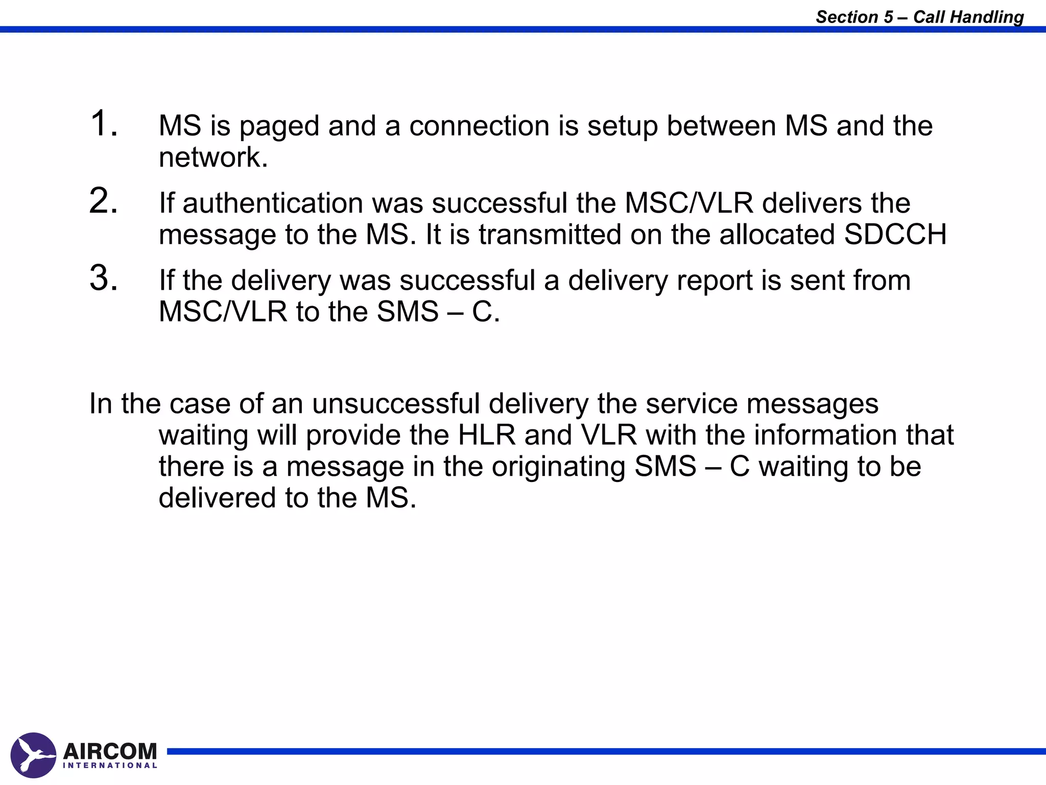
Downloaded 9,355 times
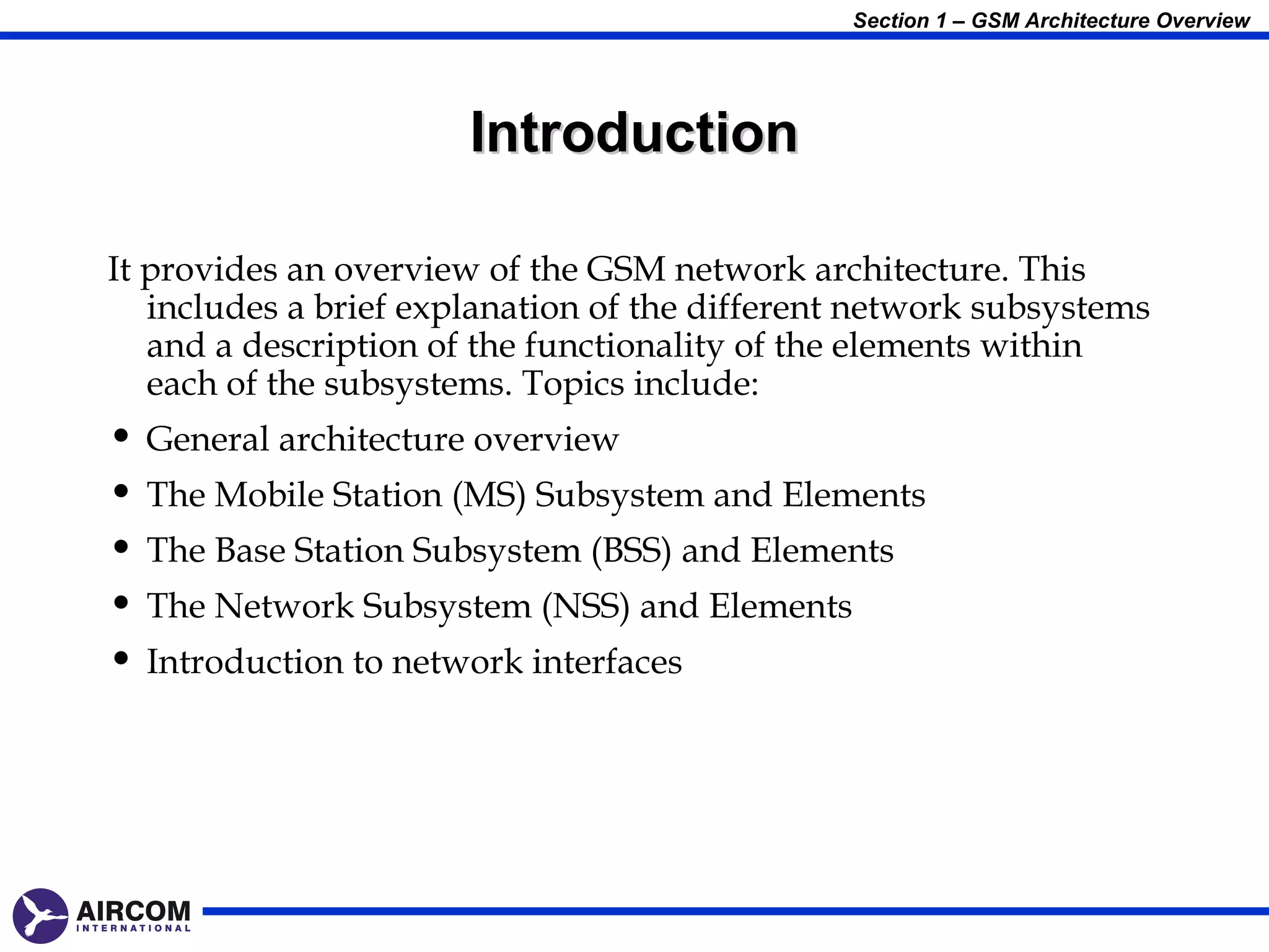
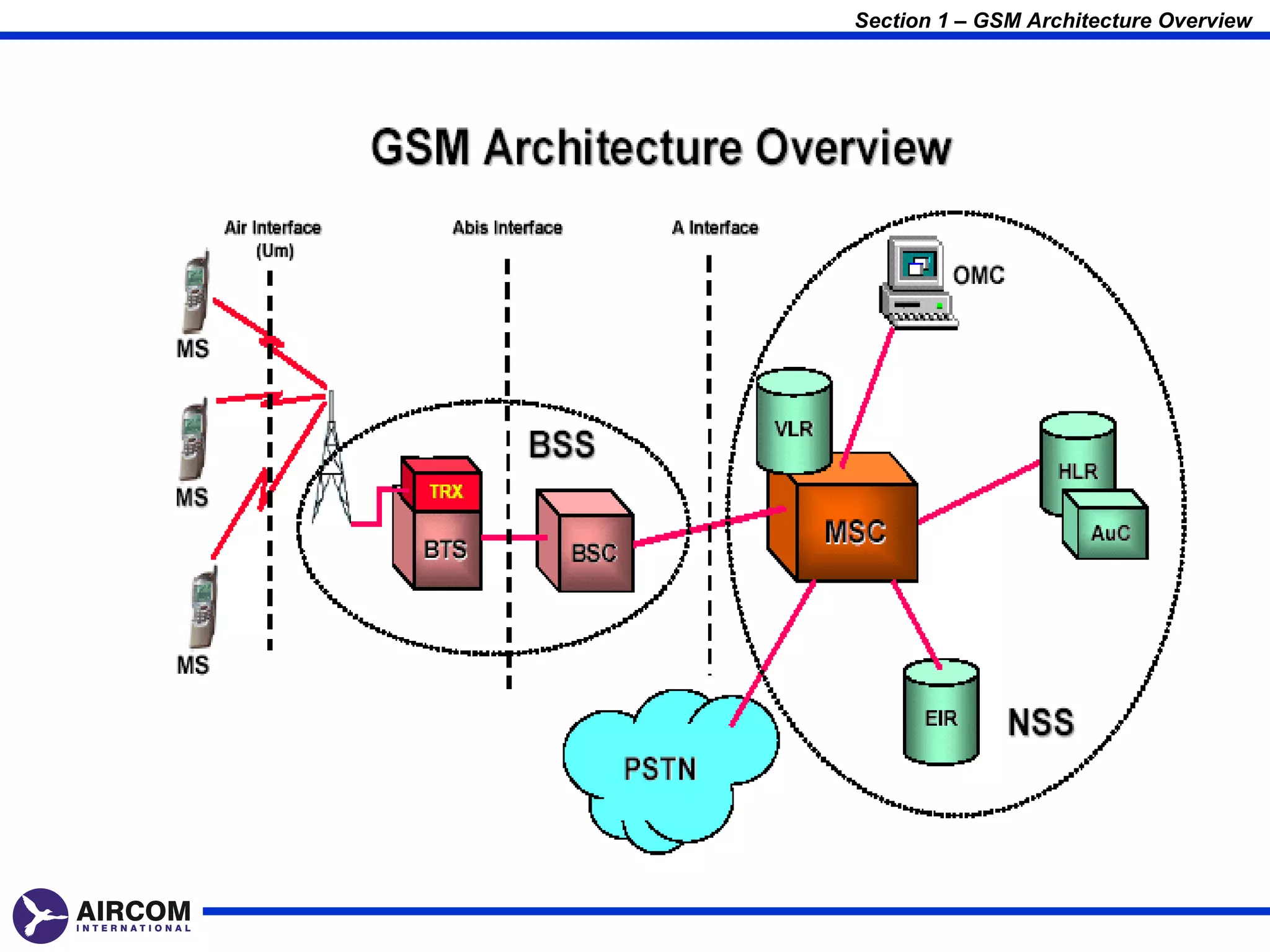
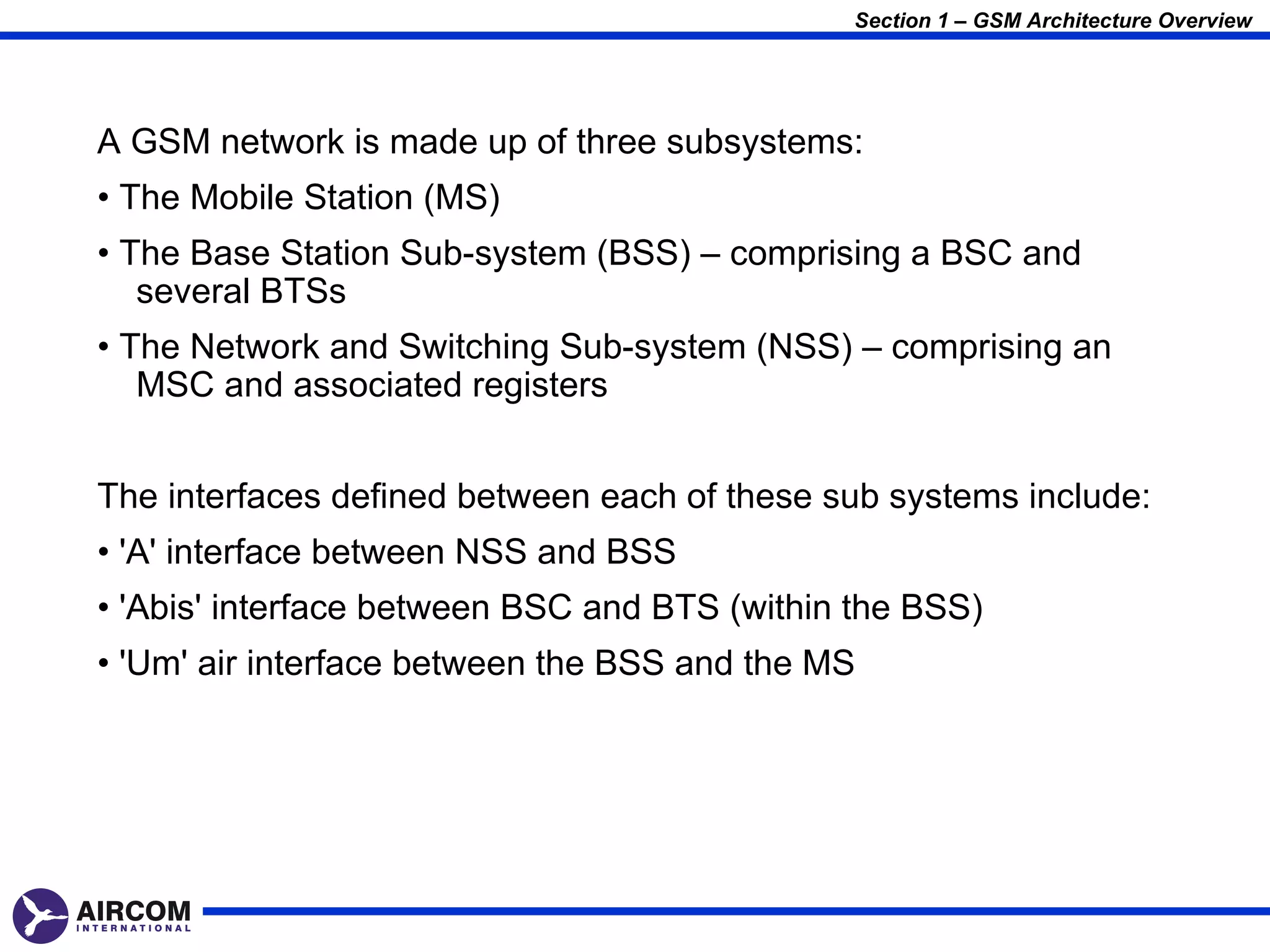
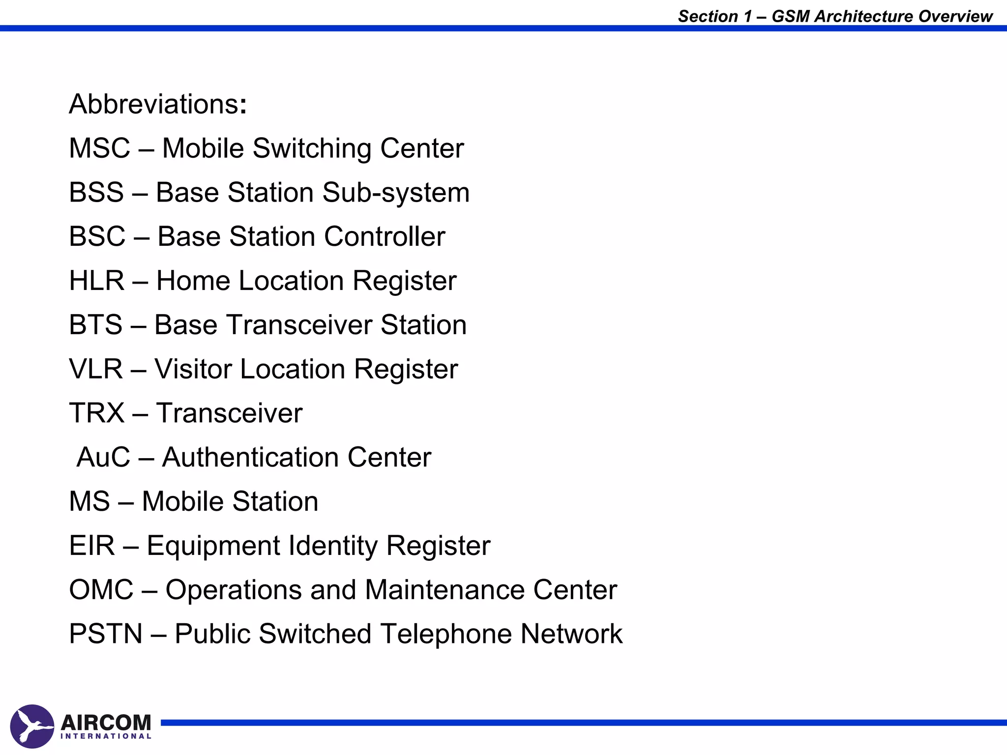
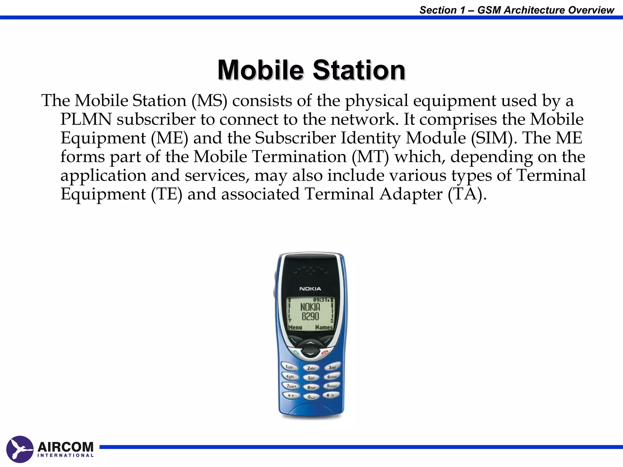
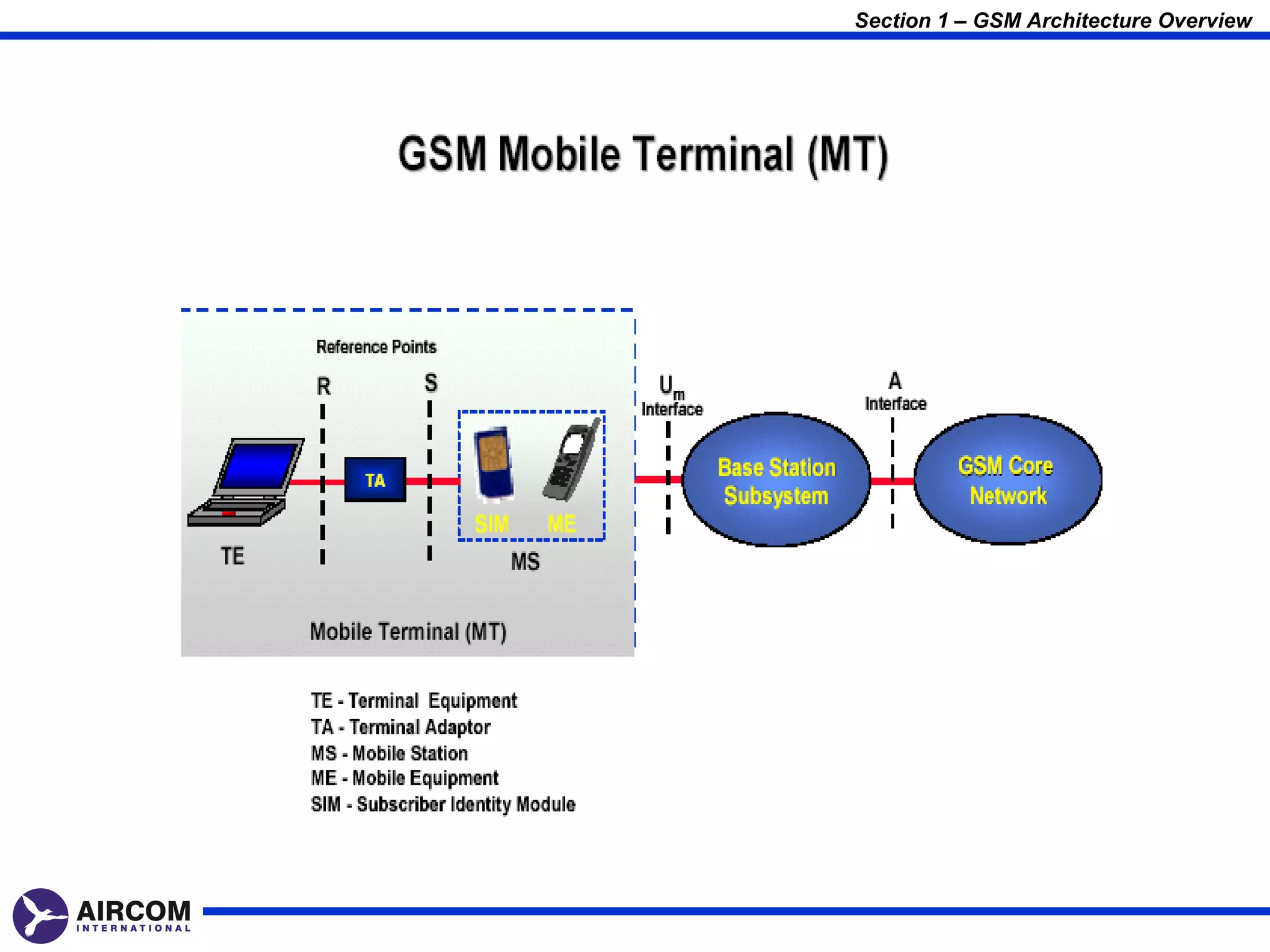
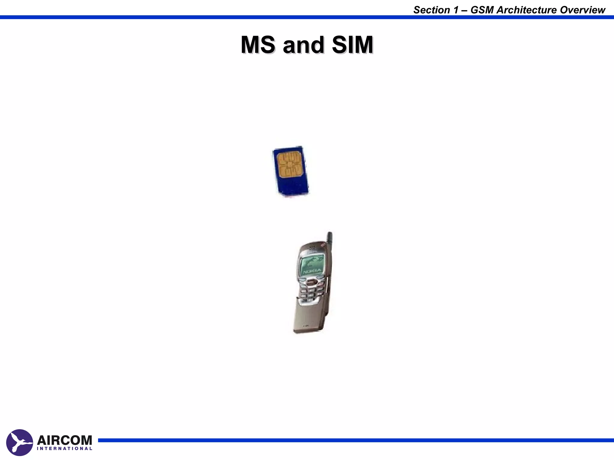
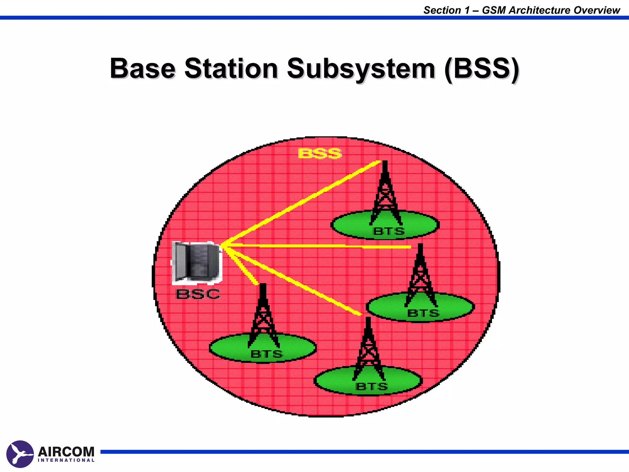
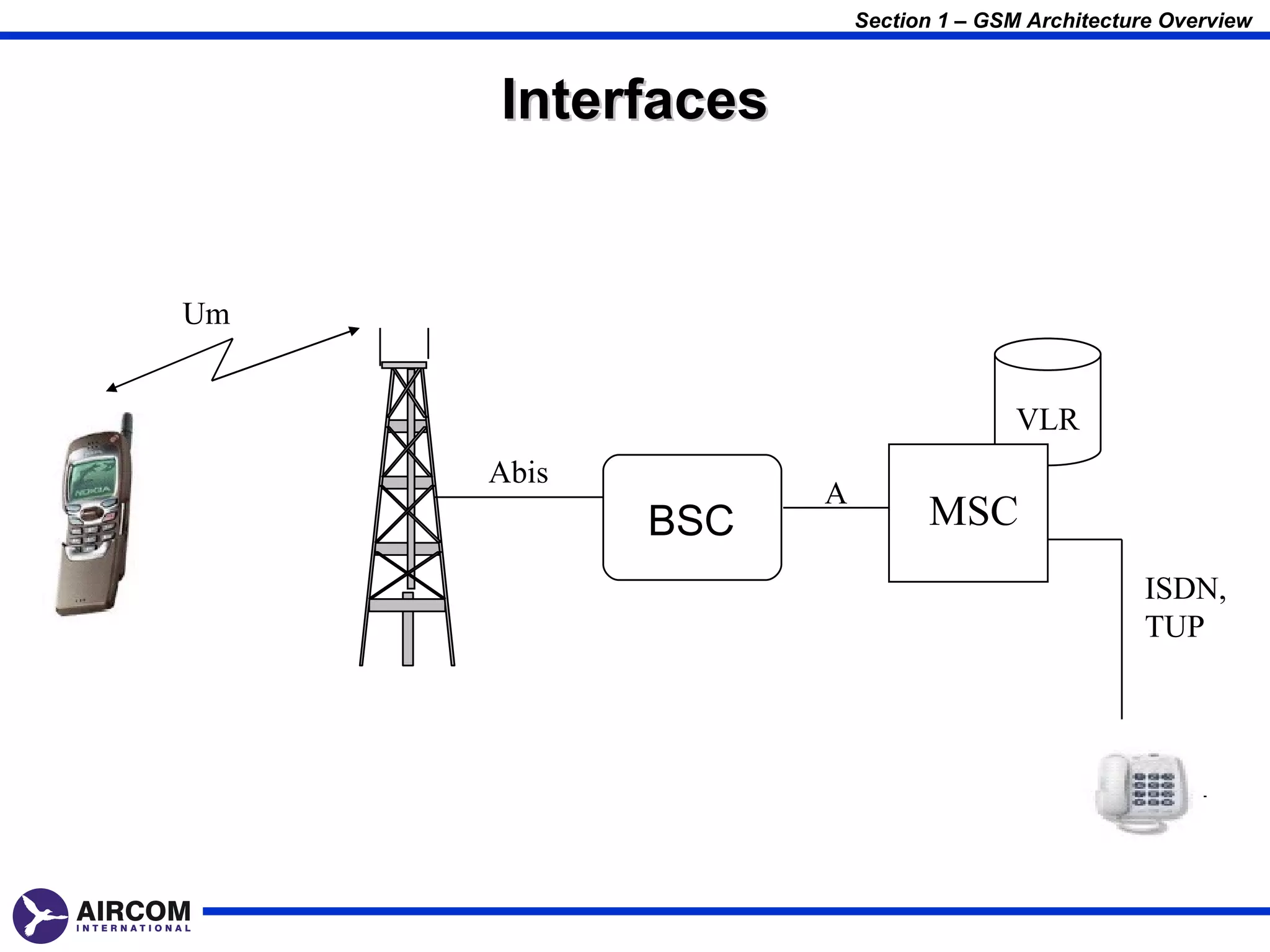

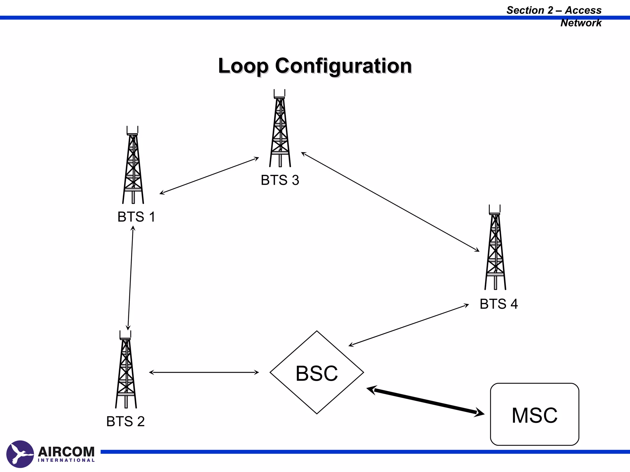


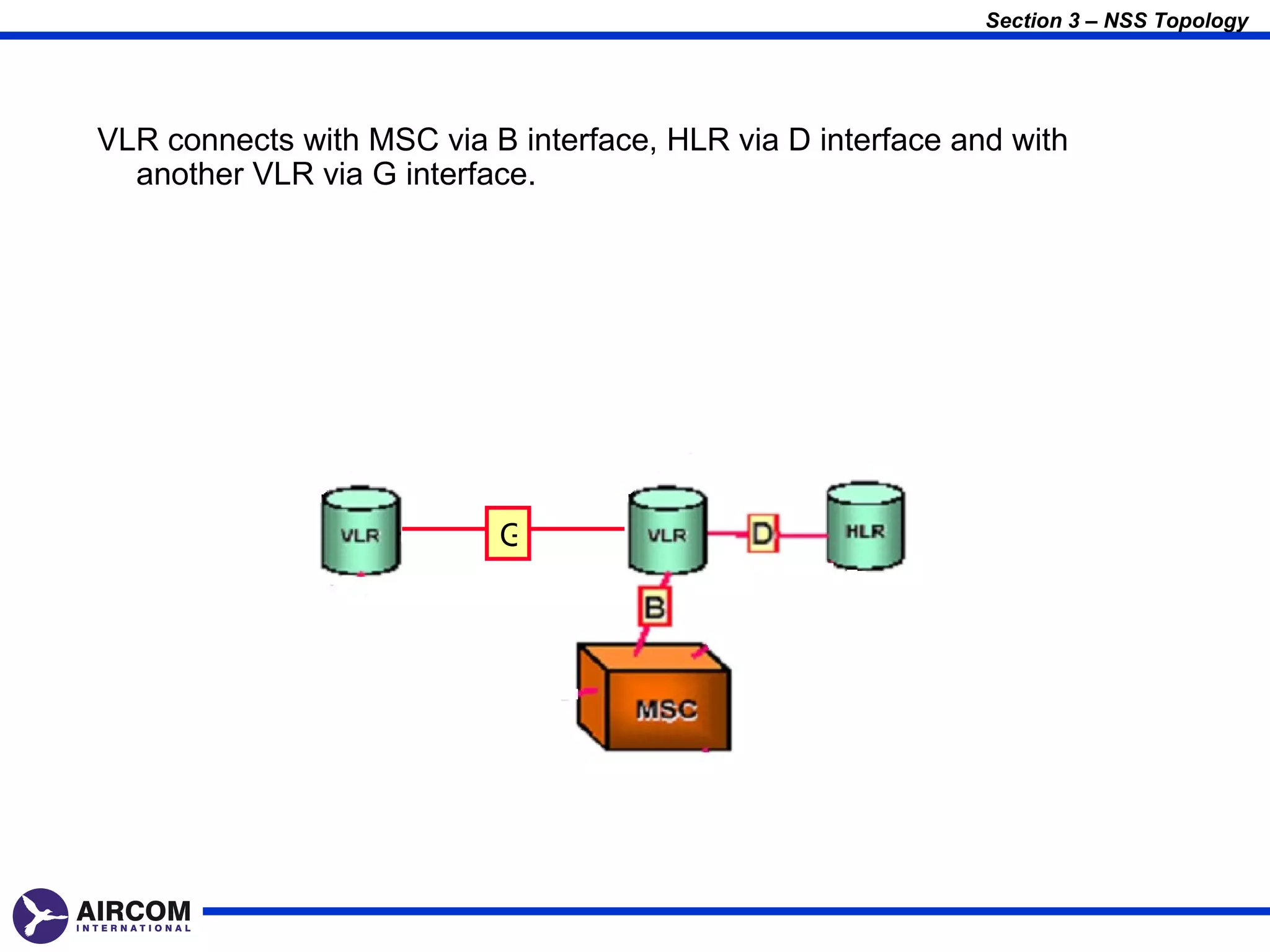


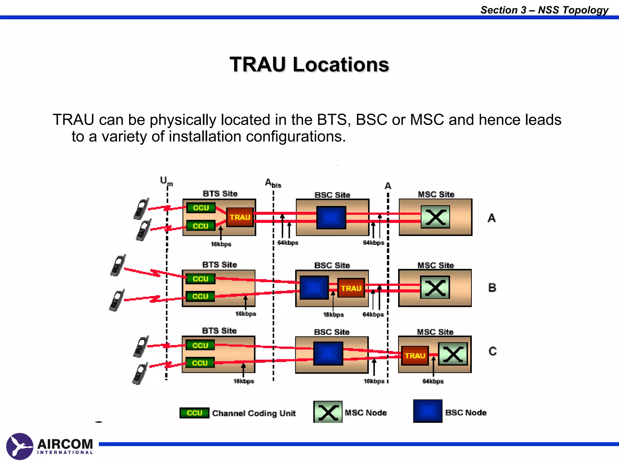


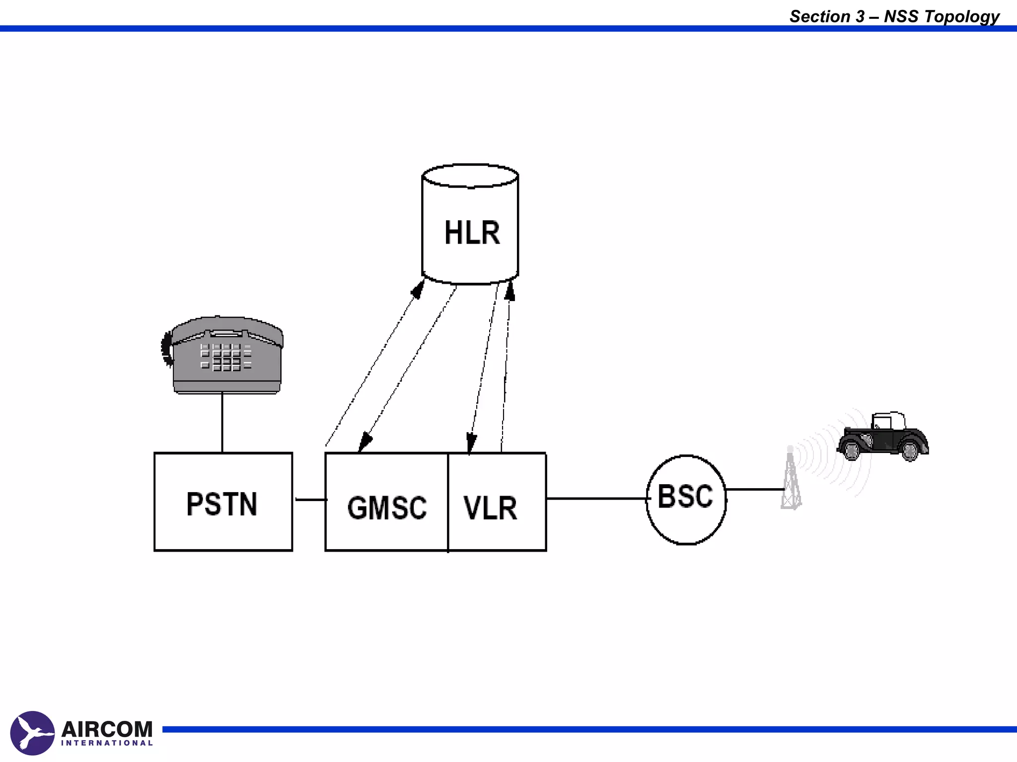


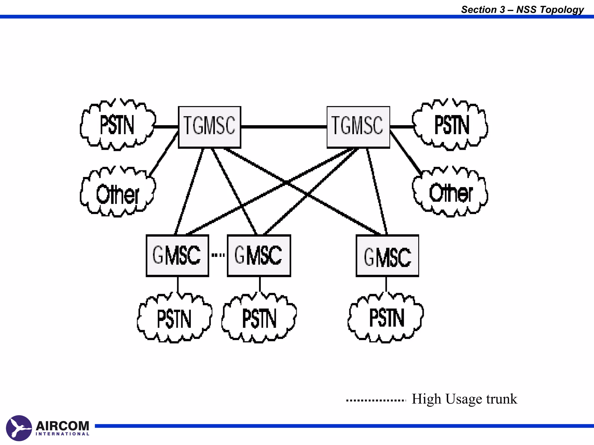


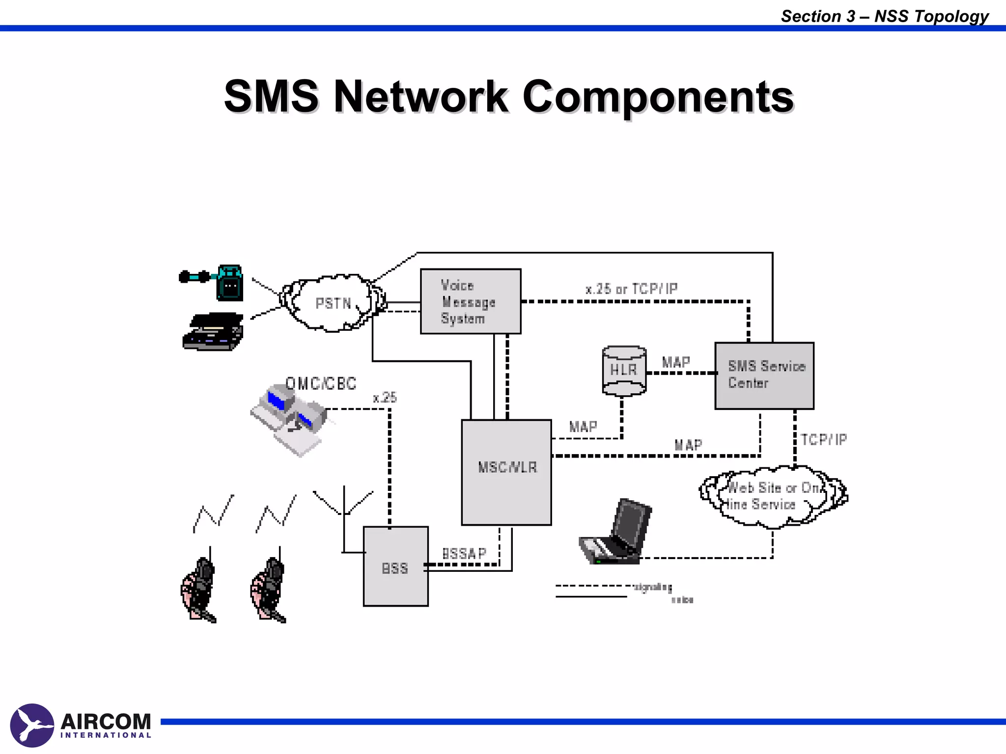


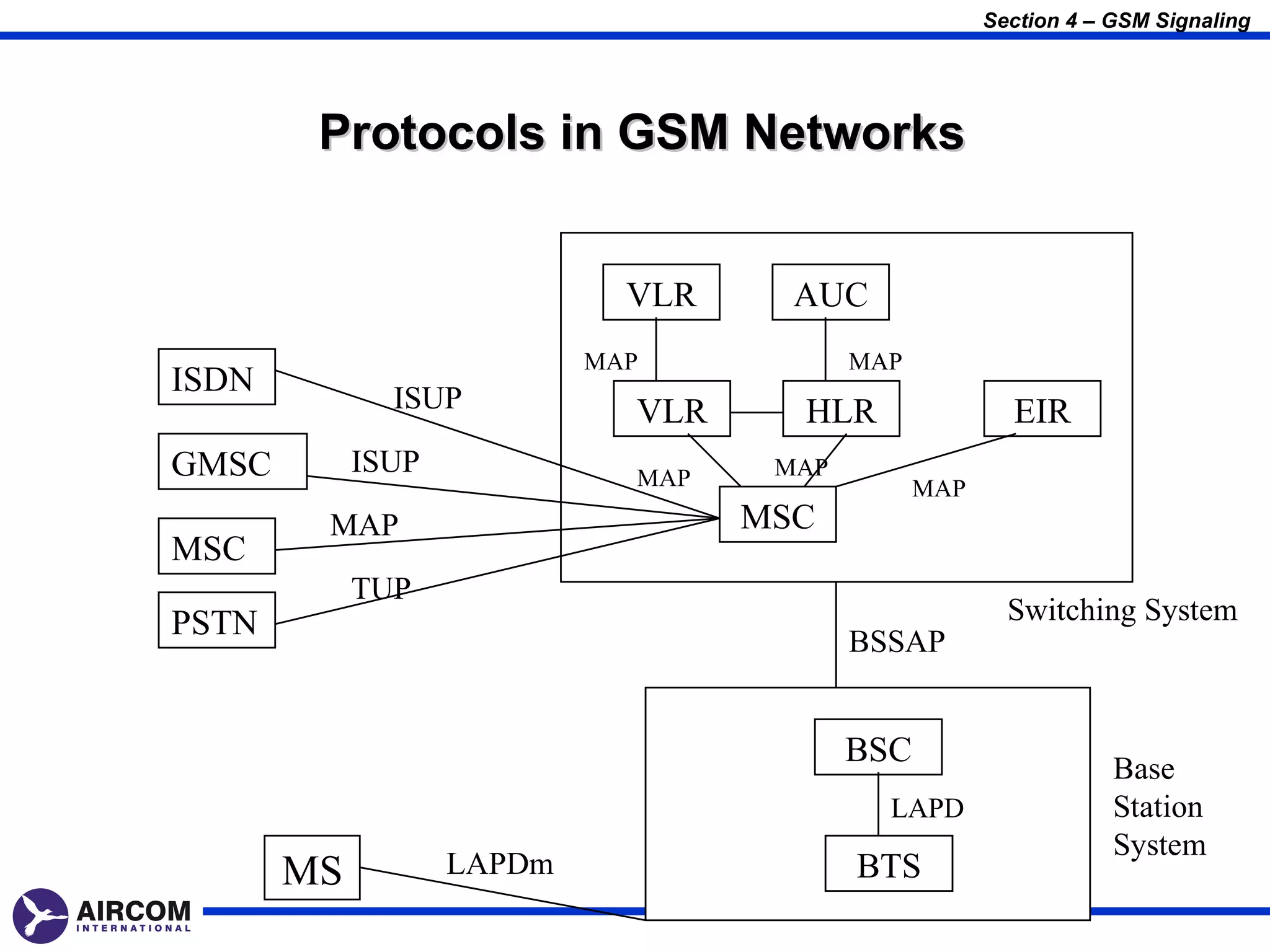


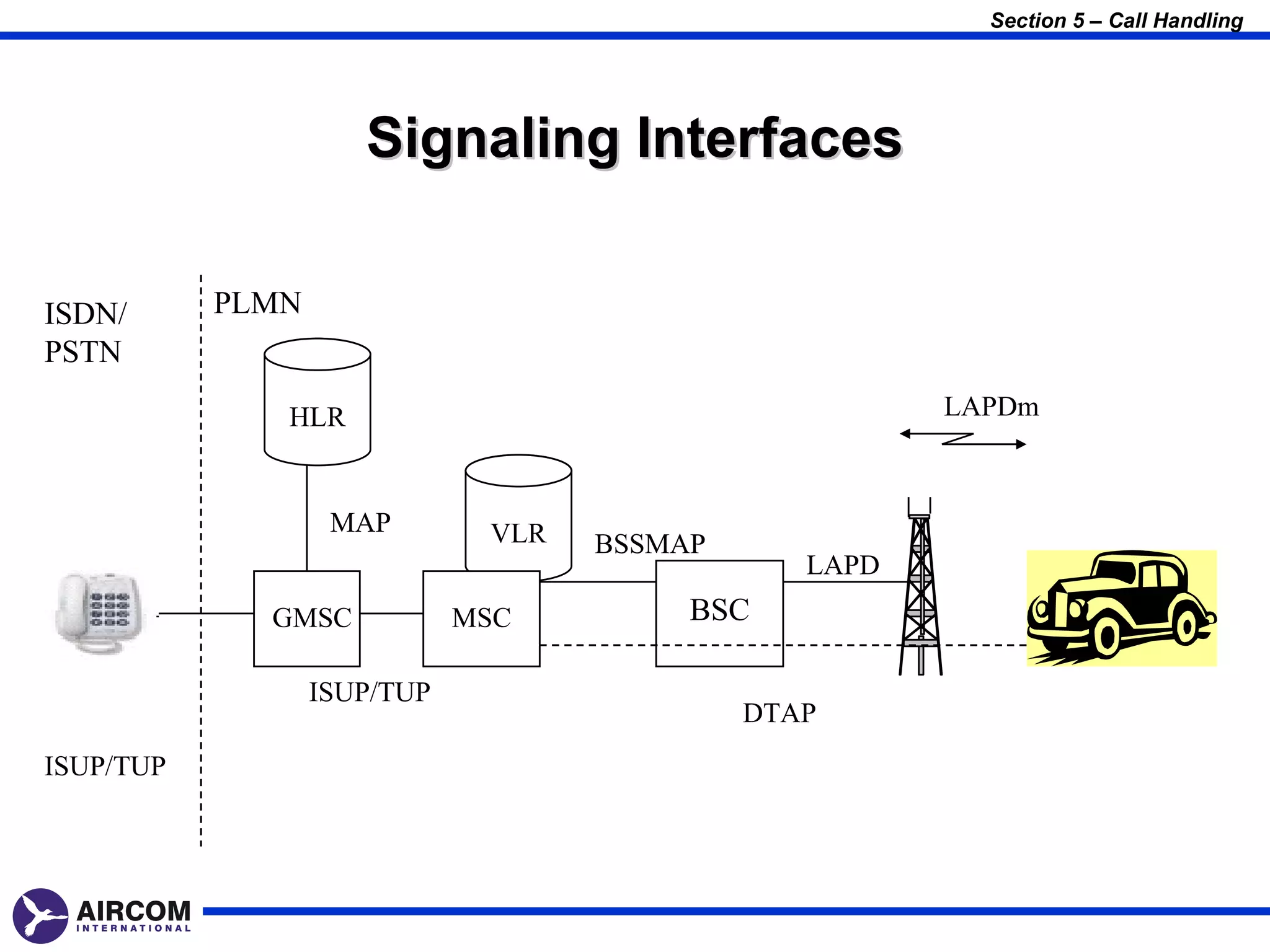


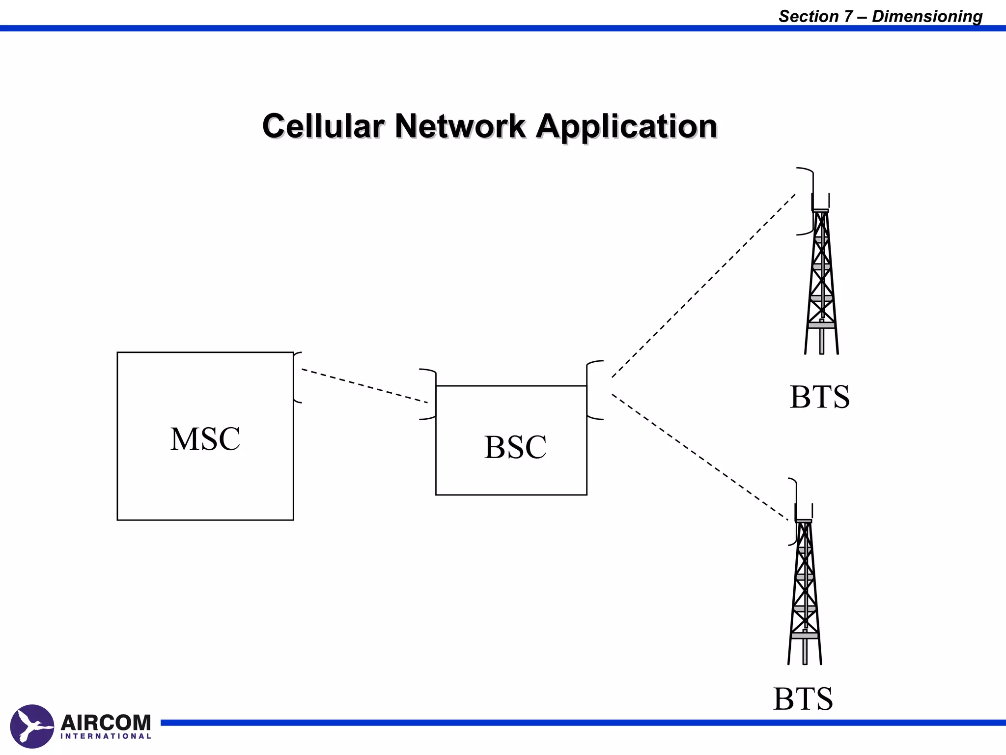


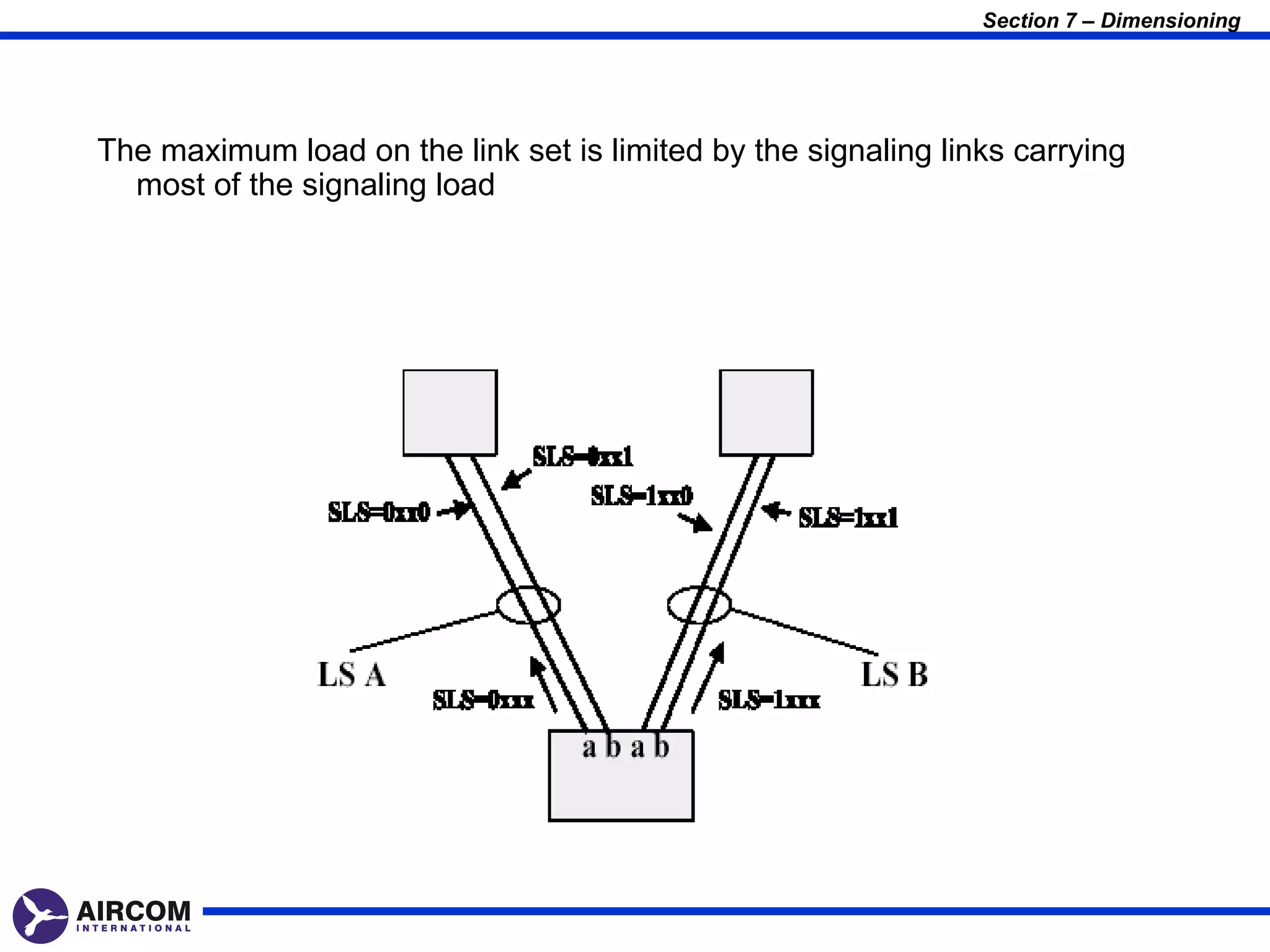


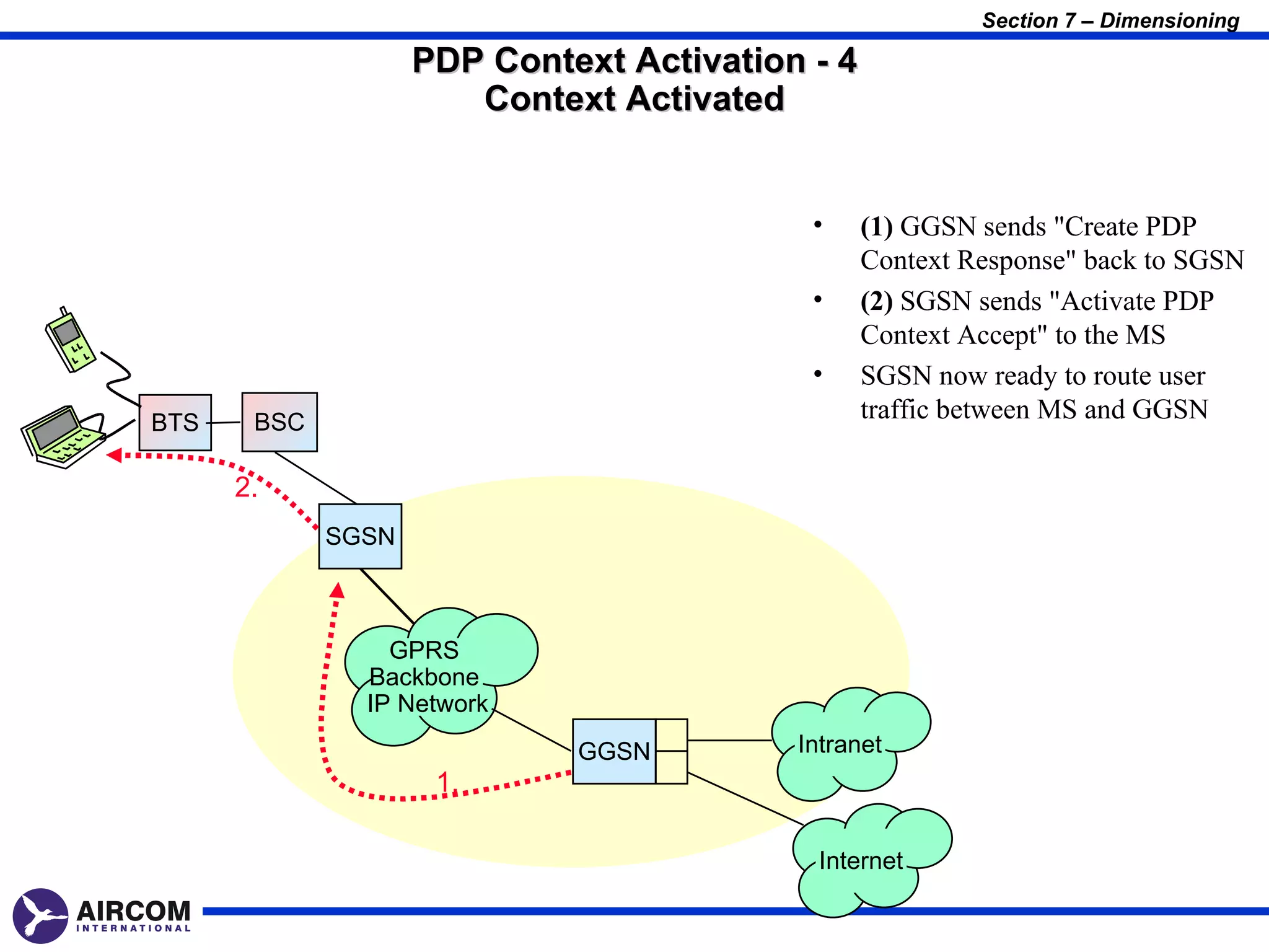


The document provides an overview of the GSM network architecture, including its three main subsystems: the Mobile Station subsystem, the Base Station Subsystem, and the Network Switching Subsystem. It describes the key elements and interfaces within each subsystem, such as the Mobile Station, Base Transceiver Station, Base Station Controller, Mobile Switching Center, Home Location Register, and Visitor Location Register. The interfaces that connect these elements, such as the A, Abis, and Um interfaces, are also introduced.


![Vibe Coding vs. Spec-Driven Development [Free Meetup]](https://cdn.slidesharecdn.com/ss_thumbnails/vibecodingvsspecdrivendevelopment-251209105622-43f455e7-thumbnail.jpg?width=640&height=640&fit=bounds)


