Download as PDF, PPTX
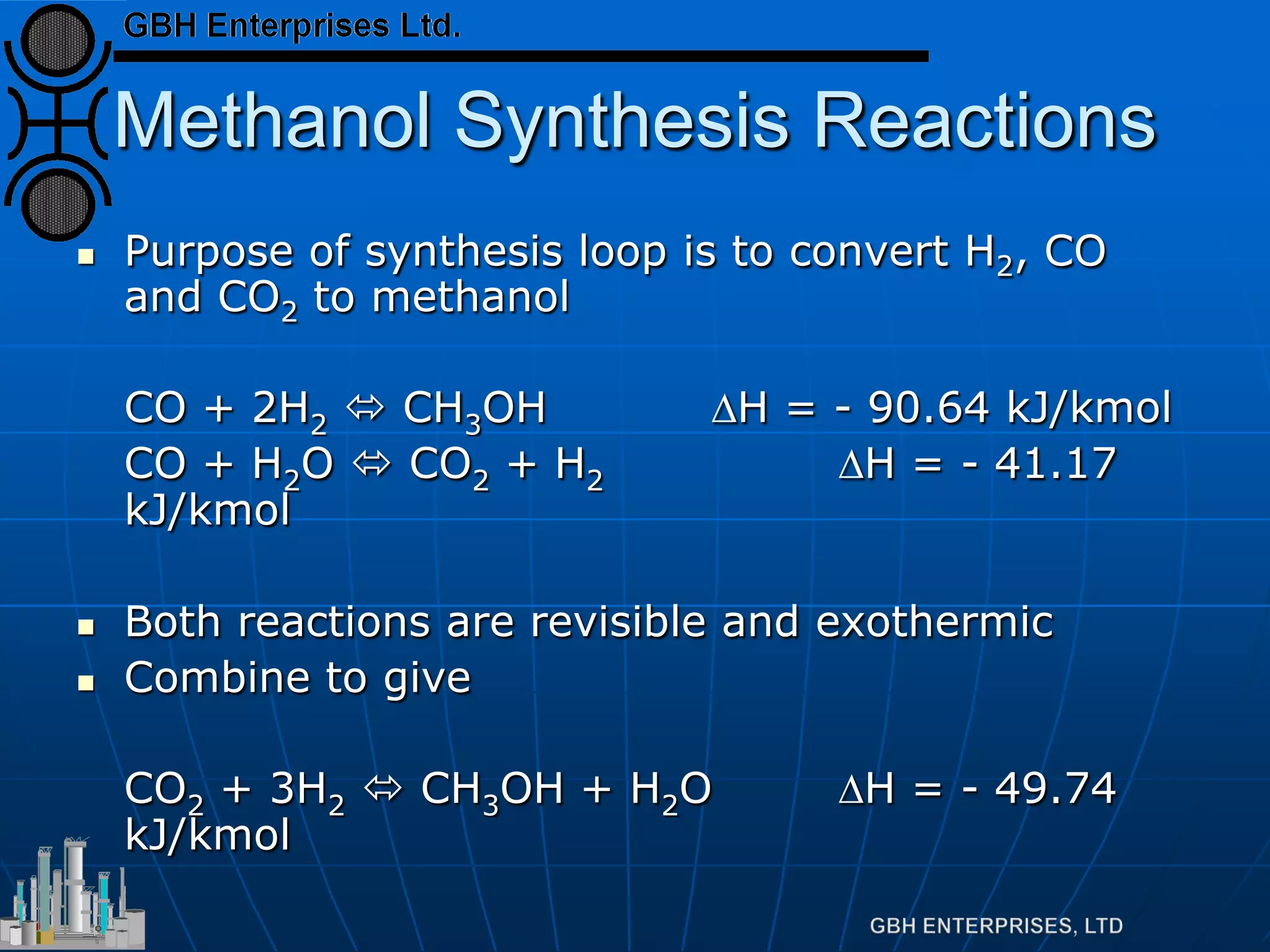
![Methanol Synthesis Reactions
Methanol is produced from CO2
Proven by use of radioactive C14
CO is shifted to CO2 and then to
methanol
Rate of reaction is given by
5.0
2
2]./[3
][
][
.exp.
OHP
COP
Activity
dt
OHdCH TRE∆−
∝](https://image.slidesharecdn.com/methanolsynthesis-theoryandoperation-130730212230-phpapp02/75/Methanol-Synthesis-Theory-and-Operation-6-2048.jpg)
![Equilibrium
Equilibrium defined by
Which can be rearranged to
Which is far more useful
[ ] [ ]
[ ] [ ]3
22
23
.
.
HPCOP
OHPOHCHP
Kp =
[ ]
[ ] [ ]3
22
2
3
.
][.
HPCOP
OHPKp
OHCHP =](https://image.slidesharecdn.com/methanolsynthesis-theoryandoperation-130730212230-phpapp02/75/Methanol-Synthesis-Theory-and-Operation-7-2048.jpg)


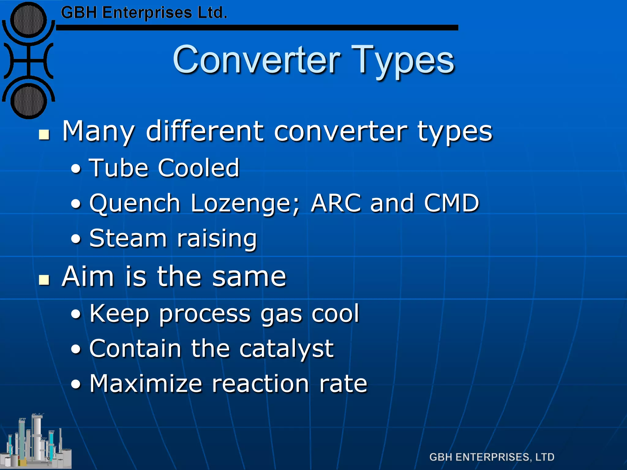
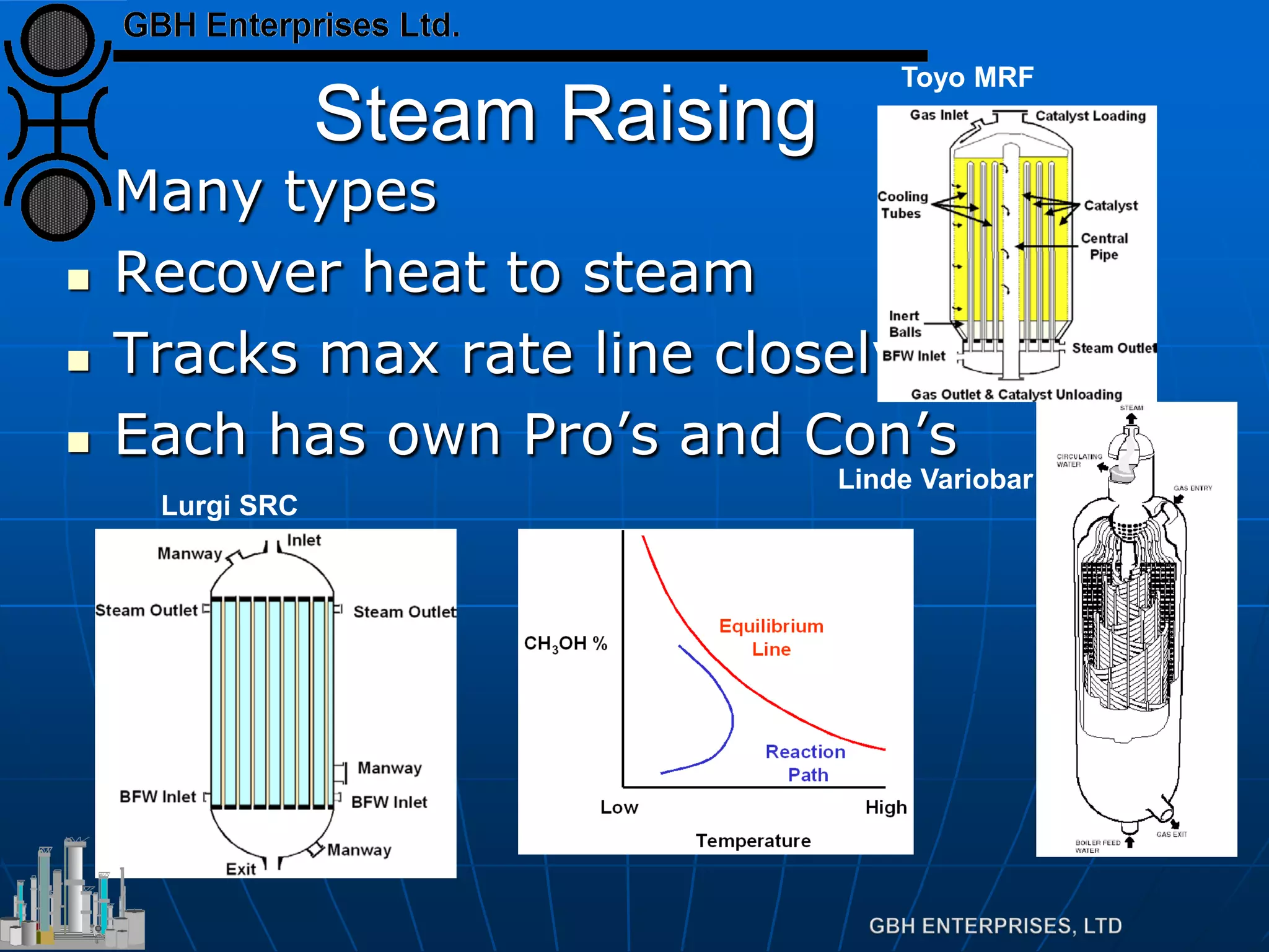


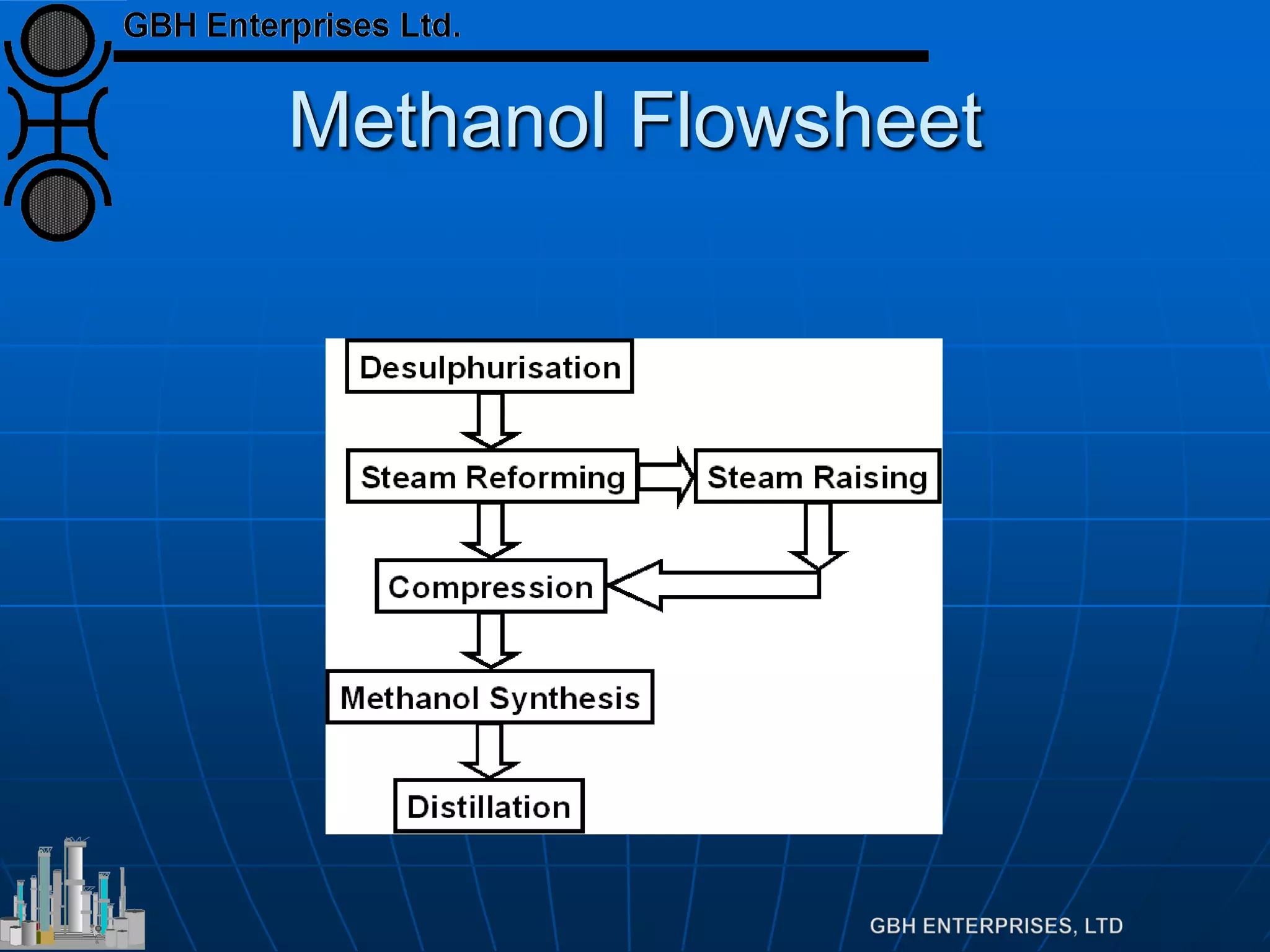
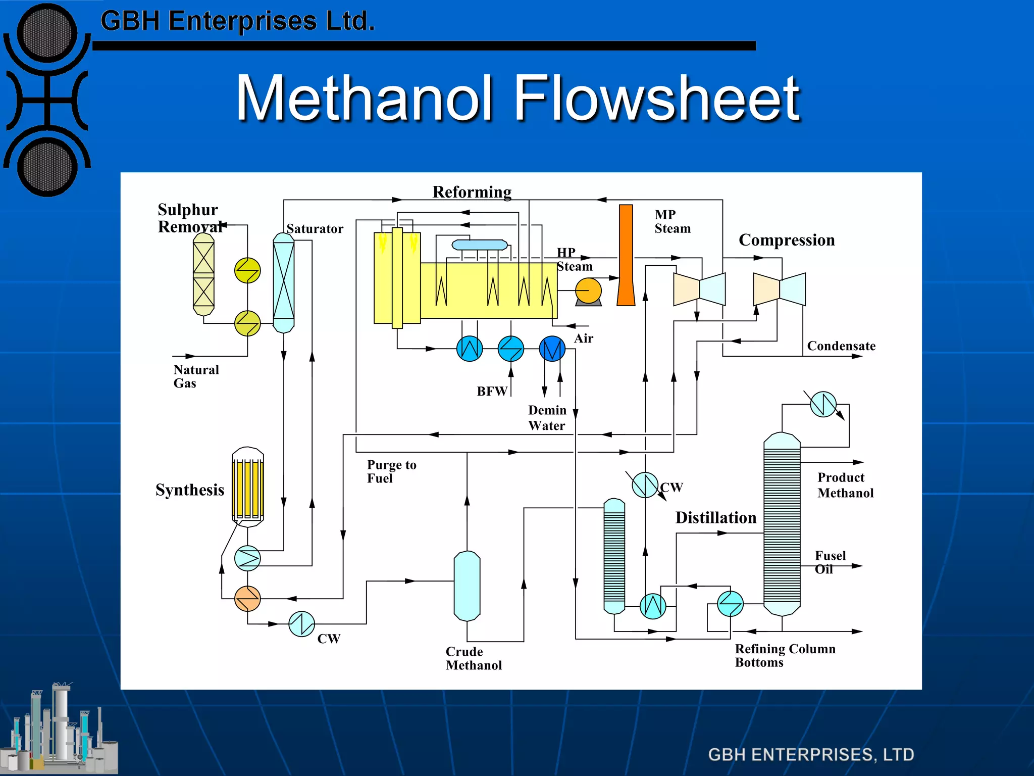
This document summarizes the theory and operation of methanol synthesis. It describes the typical methanol synthesis flowsheet that involves natural gas processing, reforming, and methanol production and purification steps. It also discusses the methanol synthesis reactions, catalysts used including their properties and deactivation mechanisms. Key factors that affect the equilibrium and kinetics of the synthesis reactions like temperature, pressure and catalyst activity are described. Methods to maximize the reaction rate within operational constraints are covered.


