
Recommended
Recommended
More Related Content
What's hot
What's hot (20)
Viewers also liked
Viewers also liked (17)
Similar to LS-RDIO0808 PLC Wireless link module Modbus RTU
Similar to LS-RDIO0808 PLC Wireless link module Modbus RTU (20)
Recently uploaded
Recently uploaded (20)
LS-RDIO0808 PLC Wireless link module Modbus RTU
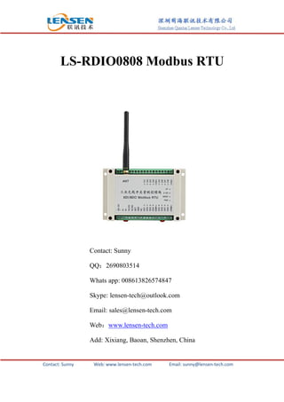
- 1. Contact: Sunny Web: www.lensen-tech.com Email: sunny@lensen-tech.com LS-RDIO0808 Modbus RTU Contact: Sunny QQ:2690803514 Whats app: 008613826574847 Skype: lensen-tech@outlook.com Email: sales@lensen-tech.com Web:www.lensen-tech.com Add: Xixiang, Baoan, Shenzhen, China
- 2. Contact: Sunny Web: www.lensen-tech.com Email: sunny@lensen-tech.com 1. LS-RDIO series module general introduction LS-RDIO Modbus RTU is an industrial controller designed by Lensen Technology. It supports point to point, point to multi-points wireless DI, DO, AI, AO collection and control. This transceiver has the advantage of easy installation, no program required, no communication fee. It is reliable and cost-effective substitution for rail signal cable, slip ring signal wire. This series we have 2DI/2DO module, 4DI/4DO module, 8DI/8DO module. Power output we have 2 versions, one is 100mW for 600m LOS control distance, and another one is 1W for 3km LOS control distance 2. Application Field LS-RDIO series I/O module is widely used in industry automation like factory central data process, pump control, oil monitoring, mining machinery, environment monitoring equipments, lifting devices, robots control, filling machine, mixing equipments, logistic line, AGV etc. 3. About Item Name
- 3. Contact: Sunny Web: www.lensen-tech.com Email: sunny@lensen-tech.com 4. Parameter Parameter Power output: 1W or 100mW version Power supply: 9V-30V (usually choose 24V DC or 12V DC) Control distance: 3km or (1km version) Baud rate: 1200bps Receiving sensibility: -123dBm@1200bps, -118dbm(9600bps) Networking Networking: Point to point and point to multipoint Port Description Input: 8 active DI (passive customized) Output: 8 relay passive outputs, contact max load AC250V/5A,DC30V/5A (Active output 0-5V customized) Communication port RS485 (wireless RS485 customize) Current Transmit current: <600mA (or 100mA version) Receiving current: <50mA (or 20mA version) General Frequency: 433MHz, 400, 450, 470 or other band Channel No: 16 channels,can change via DIP switch Physical Properties Dimension: 145×90×40(mm) Antenna Connector: SMA,vehicle antenna with 1.5m cable Temperature: 35℃~+75℃( industrial) Mounting method: Standard 3.5 inch industrial guild rail
- 4. Contact: Sunny Web: www.lensen-tech.com Email: sunny@lensen-tech.com 5. LS-RDIO series I/O control application example 1) Point to point control Remarks: Module A Module B Input and Output Correspondence A(DI1-DI8) B(DO1-DO8) DI1-DI8 of A to control DO1-DO8 of B respectively A(DO1-DO8) B(DI1-DI8) DO1-DO8 of A is controlled by DI1-DI8 of B respectively Notes: A and B should use the same channel
- 5. Contact: Sunny Web: www.lensen-tech.com Email: sunny@lensen-tech.com 2) One master to control 2 slaves Remarks: Master Module Slave Module Input and Output Correspondence A(DI1-DI4) B1(DO1-DO4) DI1-DI4 of A control DO1-DO4 of B1 respectively A(DI5-DI8) B2(DO1-DO4) DI5-DI8 of A control DO1-DO4 of B2 respectively A(DO1-DO4) B1(DI1-DI4) DO1-DO4 of A is controlled by DI1-DI4 of B1 A(DO5-DO8) B2(DI1-DI4) DO5-DO8 of A is controlled by DI1-DI4 of B2 Notes: A and B should use the same channel
- 6. Contact: Sunny Web: www.lensen-tech.com Email: sunny@lensen-tech.com 3) One master to control 4 slaves Remarks: Master Slave Input and Output Correspondence A(DI1-DI2) B1(DO1-DO2) DI1-DI2 of A control DO1-DO2 of B1 A(DI3-DI4) B2(DO1-DO2) DI3-DI4 of A control DO1-DO2 of B2 A(DI5-DI6) B3(DO1-DO2) DI5-DI6 of A control DO1-DO2 of B3 A(DI7-DI8) B4(DO1-DO2) DI7-DI8 of A control DO1-DO2 of B4 A(DO1-DO2) B1(DI1-DI2) DO1-DO2 of A controlled by DI1-DI2 of B A(DO3-DO4) B2(DI1-DI2) DO3-DO4 of A controlled by DI1-DI2 of B2 A(DO5-DO6) B3(DI1-DI2) DO5-DO6 of A controlled by DI1-DI2 of B3 A(DO7-DO8) B4(DI1-DI2) DO7-DO8 of A controlled by DI1-DI2 of B4 Notes: A and B should use the same channel
- 7. Contact: Sunny Web: www.lensen-tech.com Email: sunny@lensen-tech.com 4) One master to 8 salves Remarks: Master Salve Input and control correspondence A(DI1) B1(DO1) DI1 of A control DO1 of B1 A(DI2) B2(DO1) DI2 of A control DO1 of B1 A(DI3) B3(DO1) DI3 of A control DO1 of B1 A(DI4) B4(DO1) DI4of A control DO1 of B1 A(DI5) B5(DO1) DI5 of A control DO1 of B1 A(DI6) B6(DO1) DI6 of A control DO1 of B1 A(DI7) B7(DO1) DI7 of A control DO1 of B1 A(DI8) B8(DO1) DI8 of A control DO1 of B1 A(DO1) B1(DI1) DO1 of A is controlled by DI1 of B1 A(DO8) B8(DI1) DO8 of A is controlled by DI1 of B8 Note: module A and B should use the same channel;
- 8. Contact: Sunny Web: www.lensen-tech.com Email: sunny@lensen-tech.com 5) To communicate with PC/PLC 6. Modbus RTU communication and value calculation A. Register types: Register types Read command Write command (Control command) Power off Function coil register 0x01 Input --not support Output-support Not keep Can read input value Hold register 0x03 1) Coil register: Input: it is not convenient to read 8 I/O at one time. In order to control each I/O correspondingly, we defined coil register. The register address is 0x0000-0x0007. Output: it is not convenient to control 8 I/O at one time. In order to control each I/O correspondingly, we defined coil register whose address is 0x0020-0x0028. Note: The coil is not extra resource, just a method for register addressing---addressing by bit. 2) Holding register: a. value of input channels: 0x0000 Note: addressing by bit means we only use the first 8 bits; bit0 to bit7 corresponds with I / O1 to I / O8; b: feedback and value of output channels: 0x0040
- 9. Contact: Sunny Web: www.lensen-tech.com Email: sunny@lensen-tech.com Note: addressing by bit means bit 0 corresponds with 1/O1, bit 7 corresponds with 1/O8, bit 8-bit 15 corresponding value we write 0. 3) Reading method: Coil register: Directly read the responding register. 1 means OFF, 0 means ON. Holding register: Can read all 8 inputs state one time. We only use bit0-bit7 of this 16-bit register; each bit represents the state of an input. 4) Control methods: a. Use the coil--- directly writes on the corresponding coil register you can control output. b. Use the holding register--- eight outputs share 1 holding register, so you can manage each bit separately to control the responding output. B. About register control IC Read/ write Function code Products apply passage IC type PLC ID Modbus ID DI1 Coil reg. 1 0 read 01 RDIO0202 RDIO0404 RDIO0808 Holding reg. 40001.0 0.0 read 03 DI2 Coil reg. 2 1 read 01 Holding reg. 40001.1 0.1 read 03 DI3 Coil reg. 3 2 read 01 RDIO0404 RDIO0808 Holding reg. 40001.2 0.2 read 03 DI4 Coil reg. 4 3 read 01 Holding reg. 40001.3 0.3 read 03 DI5 Coil reg. 5 4 read 01 RDIO0808 Holding reg. 40001.4 0.4 read 03 DI6 Coil reg. 6 5 read 01 Holding reg. 40001.5 0.5 read 03 DI7 Coil reg. 7 6 read 01 Holding reg. 40001.6 0.6 read 03 DI8 Coil reg. 8 7 read 01 Holding reg. 40001.7 0.7 read 03 DO1 Coil reg. 33 32 Read/ write 01/05 RDIO0202 RDIO0404 RDIO0808 Holding reg. 40065.0 64.0 Read/ write 03/06 DO2 Coil reg. 34 33 Read/ write 01/05 Holding reg. 40065.1 64.1 Read/ write 03/06 DO3 Coil reg. 35 34 Read/ write 01/05 RDIO0404 RDIO0808Holding reg. 40065.2 64.2 Read/ write 03/06 DO4 Coil reg. 36 35 Read/ 01/05
- 10. Contact: Sunny Web: www.lensen-tech.com Email: sunny@lensen-tech.com write Holding reg. 40065.3 64.3 Read/ write 03/06 DO5 Coil reg. 37 36 Read/ write 01/05 RDIO0808 Holding reg. 40065.4 64.4 Read/ write 03/06 DO6 Coil reg. 38 37 Read/ write 01/05 Holding reg. 40065.5 64.5 Read/ write 03/06 DO7 Coil reg. 39 38 Read/ write 01/05 Holding reg. 40065.6 64.6 Read/ write 03/06 DO8 Coil reg. 40 39 Read/ write 01/05 Holding reg. 40065.7 64.7 Read/ write 03/06 7. DIP Setting:
- 11. Contact: Sunny Web: www.lensen-tech.com Email: sunny@lensen-tech.com 1) Outer(right side) DIP 1-4 are used for channel setting. Please check the following definition: Channel No. DIP Setting Channel No. DIP Setting Channel No. DIP setting Channel No. DIP setting 1 1234 2 1234 3 1234 4 1234 5 1234 6 1234 7 1234 8 1234 2) Outer(right side) DIP 5-8 are used for mode setting. Please check the following definition DIP Status Function Remarks 5 OFF Conventional modules ON Customized modules 6、7 OFF、OFF 1 to 1 control Slave module’s ID set to 1 6、7 OFF、ON 1 to 2 slaves control 2 slave modules’ ID set to 1 and 2 respectively 6、7 ON、OFF 1 to 4 slaves control 4 salve modules’ ID set to 1, 2, 3 and 4 respectively 6、7 ON、ON 1 to 8 slave control 8 slave modules’ ID set to 1, 2, 3, 4, 5, 6, 7 and 8 respectively 8 OFF Slave mode ON Master mode 3) Interior(left side) DIP 1-8 are used for module’s ID setting (also Modbus slaves’ ID.), for example ID DIP setting ID DIP setting ID DIP setting 1 2 3 4 5 6 7 8 9 10 11 12 13 14 15 DIP for slaves with ID 16-254, please refer the above regulation to set
- 12. Contact: Sunny Web: www.lensen-tech.com Email: sunny@lensen-tech.com 8. How to connect LS-RDIO series Modbus RTU 9. LS-RDIO series how to choose proper item: Item No. Distance I/O numbers Power supply Interface LS-RDIO 0202 600m、3000m 2DI、2DO 9-36V DC RS-485LS-RDIO 0404 4DI、4DO LS-RDIO 0808 8DI、8DO