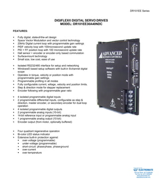
3. ADVANCED MOTION CONTROLS DR101EE Series
Sold & Serviced By:
Page 3 of 7
SPECIFICATIONS:
POWER STAGE SPECIFICATIONS DR101EE30A40NDC
DC SUPPLY VOLTAGE 60…400 VDC
PEAK CURRENT 30A (21.2Arms)
MAXIMUM CONTINUOUS CURRENT 15A (10.6Arms)
MINIMUM LOAD INDUCTANCE 600 μH
SWITCHING FREQUENCY 20 kHz
HEATSINK (BASEPLATE) TEMPERATURE RANGE 0 to 65 ºC, disables at 65 ºC
POWER DISSIPATION AT CONTINUOUS CURRENT 300W
MIN. UNDER VOLTAGE SHUTDOWN 60 VDC
MAX. OVER-VOLTAGE SHUTDOWN 425 VDC
MECHANICAL SPECIFICATIONS
POWER CONNECTOR: P1 Screw terminals
MOTOR FEEDBACK CONNECTOR: CN3* 15-pin high density female D-sub
I/O CONNECTOR: CN2* 26-pin high density female D-sub
COMMUNICATIONS INTERFACE (RS232/485): CN1* 9-pin female D-sub
SIZE 8.00 x 5.62 x 1.60 inches
203.2 x 142.9 x 40.7 mm
WEIGHT 2.12 lb.
0.99 kg
* Mating connectors are not included.
ELECTROMATE
Toll Free Phone (877) SERVO98
Toll Free Fax (877) SERV099
www.electromate.com
sales@electromate.com
4. ADVANCED MOTION CONTROLS DR101EE Series
Commutation sensor inputs. Internal
2K pull-up to +5VDC. Can be used
with single ended or differential Hall
sensors. I
Sold & Serviced By:
Page 4 of 7
PIN FUNCTIONS:
P1 - Motor and Power Connector:
CONNECTOR PIN NAME DESCRIPTION I/O
1 MA Motor phase A O
2 MB Motor phase B O
3 MC Motor phase C O
4 POWER GND Power ground. GNDPWR
P1
5 HIGH VOLTAGE DC power input I
CN3 - Motor Feedback Connector:
CONNECTOR PIN NAME DESCRIPTION I/O
1 +Hall A I
2 +Hall B I
3 +Hall C
Encoder Input. For single
4 MOT ENC A+ I
5 MOT ENC A-Differential
ended encoder signals, leave the A–
terminal open. I
Encoder Input. For single
6 MOT ENC B+ I
7 MOT ENC B-Differential
ended encoder signals, leave the B–
terminal open. I
Encoder Input. For single
8 MOT ENC I+ I
9 MOT ENC I-Differential
ended encoder signals, leave the I–
terminal open. I
10 -Hall A* See CN3-1. Leave open in case of
single ended Hall sensors.
I
11 -Hall B* See CN3-2. Leave open in case of
single ended Hall sensors.
I
12 SGND Signal ground SGND
13 +5V OUT +5V @ 250mA max. Short-circuit
protected.
O
14 PAI3 Programmable analog input, single
ended, 10-bit
I
CN3
15 -Hall C* See CN3-3. Leave open in case of
single ended Hall sensors.
I
CN2 – I/O Connector:
CONNECTOR PIN NAME DESCRIPTION I/O
1 PDO1
Isolated programmable digital output,
24V @ 50mA max. Referenced to pin 8,
Output Common.
O
2 OUTPUT COMMON Digital output common. OGND
CN2
3 PDO2
Isolated programmable digital output,
24V @ 50mA max. Referenced to pin 8,
Output Common.
O
ELECTROMATE
Toll Free Phone (877) SERVO98
Toll Free Fax (877) SERV099
www.electromate.com
sales@electromate.com
5. ADVANCED MOTION CONTROLS DR101EE Series
Differential reference signal input, 14-bit
resolution. Can also be used as
programmable analog input 1. I
4 +REF I
5 -REF
6 PAI2 Programmable analog input I
7 PAO1 Programmable analog output O
8 OUTPUT PULL-UP Digital output pull-up via 5K resistor. I
9 -PDI6 Programmable Input (see CN2-18) or
CN1 I
Sold & Serviced By:
Page 5 of 7
Direction- or Aux Enc B-I
10 PDO3
Isolated programmable digital output,
24V @ 50mA max. Referenced to pin 8,
Output Common.
O
11 PDI1
Isolated programmable digital input,
24V @ 5mA max. Referenced to pin 15,
Input Common.
I
12 PDI2
Isolated programmable digital input,
24V @ 5mA max. Referenced to pin 15,
Input Common.
I
13 PDI3
Isolated programmable digital input,
24V @ 5mA max. Referenced to pin 15,
Input Common.
I
14 PDO4
Isolated programmable digital output,
24V @ 50mA max. Referenced to pin 8,
Output Common.
O
15 Input Common Digital input common. Can also be used
to pull-up digital inputs.
IGND
16 AGND Analog ground AGND
17 +PDI5 Programmable differential digital input,
or Step+ or Aux Enc A+
I
18 +PDI6 Programmable, differential digital input
or Direction+ or Aux Enc B+
I
19 PDI4
Isolated programmable digital input,
24V @ 5mA max. Referenced to pin 15,
Input Common.
I
20 Encoder Channel A+ Output (from connector CN3),
O
21 Encoder Channel A-Encoder
not buffered O
22 Encoder Channel B+ Output (from connector CN3),
O
23 Encoder Channel B-Encoder
not buffered O
24 Encoder Channel I+ Output (from connector CN3),
O
25 Encoder Channel I-Encoder
not buffered O
26 -PDI5 Programmable Input (See CN2-17) or
Step- or Aux Enc A-I
CN1 - Communications Interface (RS232/485):
CONNECTOR PIN NAME DESCRIPTION I/O
1 SELECT RS232/485 selection. Pull to ground
(CN1-5) for RS485.
2 TX/+TX RS232: Transmit; RS485: +TX O
ELECTROMATE
Toll Free Phone (877) SERVO98
Toll Free Fax (877) SERV099
www.electromate.com
sales@electromate.com
6. ADVANCED MOTION CONTROLS DR101EE Series
3 RX/+RX RS232: Receive; RS485: +RX I
4 N/C Not connected
5 SGND Signal ground SGND
6 -TX RS485: -TX O
7 N/C Not connected
8 -RX RS485: -RX I
9 N/C Not connected
Sold & Serviced By:
Page 6 of 7
ORDERING INFORMATION:
Standard model: DR101EE30A40NDCX
X indicates the current revision letter.
ELECTROMATE
Toll Free Phone (877) SERVO98
Toll Free Fax (877) SERV099
www.electromate.com
sales@electromate.com
7. ADVANCED MOTION CONTROLS DR101EE Series
Sold & Serviced By:
Page 7 of 7
MOUNTING DIMENSIONS:
ELECTROMATE
Toll Free Phone (877) SERVO98
Toll Free Fax (877) SERV099
www.electromate.com
sales@electromate.com