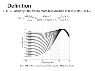
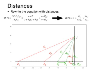
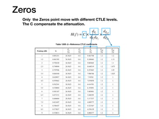
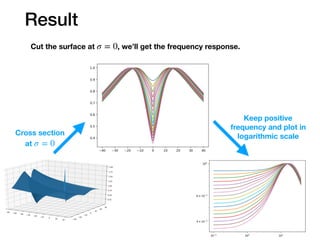
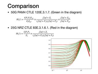
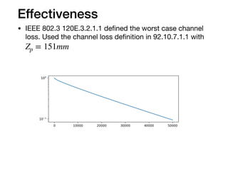
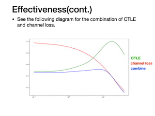
Understanding CTLE
Jeffrey.Wang

2019.8.3
Definition
• CTLE used by 50G PAM4 module is defined in 802.3 120E.3.1.7.
H( f ) =
GP1P2PLF
Z1ZLF
×
j2πf + Z1
(j2πf + P1)(j2πf + P2)
×
j2πf + ZLF
j2πf + PLF
Idea
• This transfer function comes from domain transfer
function with .

• The domain transfer function is:

• Plot the domain with CTLE level 3.5dB.(Next page)
s
σ = 0
s
s
H( f ) =
GP1P2PLF
Z1ZLF
×
j2πf + Z1
(j2πf + P1)(j2πf + P2)
×
j2πf + ZLF
j2πf + PLF
H( f ) =
GP1P2PLF
Z1ZLF
×
s + Z1
(s + P1)(s + P2)
×
s + ZLF
s + PLF
s = σ + j2πf
Poles and Zeros 3-D plot
• T
P1
P2
PLFZ1
ZLF
Distances
• Rewrite the equation with distances.
P1 P2
PLF
Z1 ZLF
̂Z1
dP1
dP2
dPLF
dZ1
dZLF
d ̂Z1
H( f ) =
GP1P2PLF
Z1ZLF
×
s + Z1
(s + P1)(s + P2)
×
s + ZLF
s + PLF
H( f ) = C ×
dZ1
dP1
dP2
×
dZLF
dPLF
̂ZLF
f
Zeros
Only the Zeros point move with different CTLE levels.
The C compensate the attenuation.
H( f ) = C ×
dZ1
dP1
dP2
×
dZLF
dPLF
Zeros
Let’s look at the distance with .
Since is larger at low frequency than at high frequency, the output of
transfer function will decrease more at low frequency.
Z1
ΔdZ1
Z1
̂Z1
dZ1
d ̂Z1
fhigh
flow
ΔdZ1
ΔdZ1
H( f ) = C ×
dZ1
dP1
dP2
×
dZLF
dPLF
Result
Cut the surface at , we’ll get the frequency response.σ = 0
Cross section
at σ = 0
Keep positive
frequency and plot in
logarithmic scale
Comparison
• 50G PAM4 CTLE 120E.3.1.7. (Green in the diagram)

• 25G NRZ CTLE 83E.3.1.6.1. (Red in the diagram)
H( f ) =
GP1P2PLF
Z1ZLF
×
j2πf + Z1
(j2πf + P1)(j2πf + P2)
×
j2πf + ZLF
j2πf + PLF
H( f ) =
GP1P2
Z1
×
j2πf + Z1
(j2πf + P1)(j2πf + P2)
Effectiveness
• IEEE 802.3 120E.3.2.1.1 defined the worst case channel
loss. Used the channel loss definition in 92.10.7.1.1 with
Zp = 151mm
Effectiveness(cont.)
• See the following diagram for the combination of CTLE
and channel loss.
CTLE
channel loss
combine
Summary
• Choose different poles and zeros can get different
surface in domain.

• Move the zeros to origin will will get more attenuation at
low frequency than at high frequency.

• CTLE may vary with different standards, but the idea is
the same.

• The effectiveness of CTLE is to compensate the channel
loss.
s

Understanding CTLE

  • 1.
  • 2.
    Definition • CTLE usedby 50G PAM4 module is defined in 802.3 120E.3.1.7. H( f ) = GP1P2PLF Z1ZLF × j2πf + Z1 (j2πf + P1)(j2πf + P2) × j2πf + ZLF j2πf + PLF
  • 3.
    Idea • This transferfunction comes from domain transfer function with . • The domain transfer function is: • Plot the domain with CTLE level 3.5dB.(Next page) s σ = 0 s s H( f ) = GP1P2PLF Z1ZLF × j2πf + Z1 (j2πf + P1)(j2πf + P2) × j2πf + ZLF j2πf + PLF H( f ) = GP1P2PLF Z1ZLF × s + Z1 (s + P1)(s + P2) × s + ZLF s + PLF s = σ + j2πf
  • 4.
    Poles and Zeros3-D plot • T P1 P2 PLFZ1 ZLF
  • 5.
    Distances • Rewrite theequation with distances. P1 P2 PLF Z1 ZLF ̂Z1 dP1 dP2 dPLF dZ1 dZLF d ̂Z1 H( f ) = GP1P2PLF Z1ZLF × s + Z1 (s + P1)(s + P2) × s + ZLF s + PLF H( f ) = C × dZ1 dP1 dP2 × dZLF dPLF ̂ZLF f
  • 6.
    Zeros Only the Zerospoint move with different CTLE levels. The C compensate the attenuation. H( f ) = C × dZ1 dP1 dP2 × dZLF dPLF
  • 7.
    Zeros Let’s look atthe distance with . Since is larger at low frequency than at high frequency, the output of transfer function will decrease more at low frequency. Z1 ΔdZ1 Z1 ̂Z1 dZ1 d ̂Z1 fhigh flow ΔdZ1 ΔdZ1 H( f ) = C × dZ1 dP1 dP2 × dZLF dPLF
  • 8.
    Result Cut the surfaceat , we’ll get the frequency response.σ = 0 Cross section at σ = 0 Keep positive frequency and plot in logarithmic scale
  • 9.
    Comparison • 50G PAM4CTLE 120E.3.1.7. (Green in the diagram) • 25G NRZ CTLE 83E.3.1.6.1. (Red in the diagram) H( f ) = GP1P2PLF Z1ZLF × j2πf + Z1 (j2πf + P1)(j2πf + P2) × j2πf + ZLF j2πf + PLF H( f ) = GP1P2 Z1 × j2πf + Z1 (j2πf + P1)(j2πf + P2)
  • 10.
    Effectiveness • IEEE 802.3120E.3.2.1.1 defined the worst case channel loss. Used the channel loss definition in 92.10.7.1.1 with Zp = 151mm
  • 11.
    Effectiveness(cont.) • See thefollowing diagram for the combination of CTLE and channel loss. CTLE channel loss combine
  • 12.
    Summary • Choose differentpoles and zeros can get different surface in domain. • Move the zeros to origin will will get more attenuation at low frequency than at high frequency. • CTLE may vary with different standards, but the idea is the same. • The effectiveness of CTLE is to compensate the channel loss. s