This document discusses the importance of radio technology and antennas in determining Wi-Fi network performance. It explains that while IP networking is important, radio signals and antennas have a greater impact on performance since they are responsible for transmitting and receiving the radio waves. The document provides an overview of key antenna concepts like gain, direction and polarization and how different antenna types and implementations can significantly affect a Wi-Fi network's stability and performance. It emphasizes that the antenna is the first component to shape the radio waves being transmitted.

![Page 5
Radios, Antennas and Other Wi-Fi Essentials
this would be a cutaway from our doughnut shape. The 5 GHz
E-Plane features two main lobes and four smaller ones — it
has a higher gain and a different coverage pattern.
This example represents a single physical antenna housing
with has two antennas inside; a 3.8 dBi vertically polarized an-tenna
for 2.4 GHz and a 5.8 dBi omnidirectional for the 5 GHz
range. It’s not uncommon to see these kinds of antennas used
by dual-radio/dual-band devices.
Interference
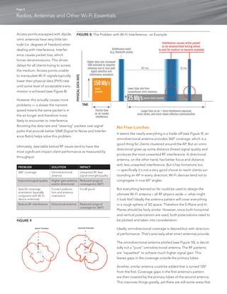
Interference — better yet, lack of it — is a critical component
of Wi-Fi performance. The ultimate goal of a wireless trans-mission
is to send a signal to another device, not necessarily
transmit RF energy everywhere.
Any additional RF energy is generally referred to as interfer-ence,
whether it is from an 802.11 device or not. When the
transmission is on the same frequency (channel) as other Wi-Fi
devices, this is co-channel interference. Co-channel interfer-ence
can dramatically degrade Wi-Fi performance.
The reason is simple. 802.11 Wi-Fi is a half-duplex transmission
technology; much like walkie-talkies. At any time, only one per-son
can talk — all others can only listen until the first speaker is
done and the channel is clear (silent). If two or more people try
to talk at the same time, each transmission is garbled and no
one can be understood. Wi-Fi works the same way.
When one Wi-Fi client is talking to an AP, all other clients must
wait for silence before they can transmit. If they don’t wait,
their transmissions will interfere with the first device. This will
cause simultaneous transmissions (mid-air collisions) that result
in corrupted packets and errors.
FIGURE 7: Dual-radio Antenna
60
30
0
330
300
270
240
210
180
150
120
60
30
0
330
300
270
240
210
180
150
120
60
30
0
330
300
270
240
210
180
150
120
60
30
0
330
300
270
240
210
180
150
120
Amplitude [dB] AZ [deg]
E-Plane H-Plane
ROLL [deg]
Amplitude [dB]
15
30
45
60
75
90
105
120
135
150
-165 180 165
-150
-135
-120
-105
-90
-75
-60
-45
-30
-15 0 0
5
10
15
20
25
30
35
40
15
30
45
60
75
90
105
120
135
150
-165 180 165
-150
-135
-120
-105
-90
-75
-60
-45
-30
-15 0 0
5
10
15
20
25
30
35
40
FIGURE 6: Omnidirectional Antenna Pattern
FIGURE 5: Horizontally Polarized Omni Antenna Orientations
INCORRECT
Orientation is mainly vertical
CORRECT
Orientation is mainly horizontal
???
Who knows what they were
trying to do here](https://image.slidesharecdn.com/wp-wifi-essentials-141010155017-conversion-gate01/85/Wp-wifi-essentials-5-320.jpg)