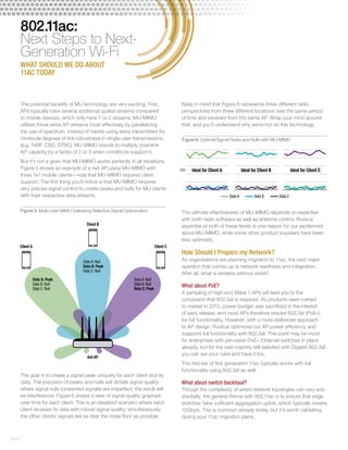
- The document discusses the differences between 802.11n and the first generation (Wave 1) and potential second generation (Wave 2) of 802.11ac wireless technology.
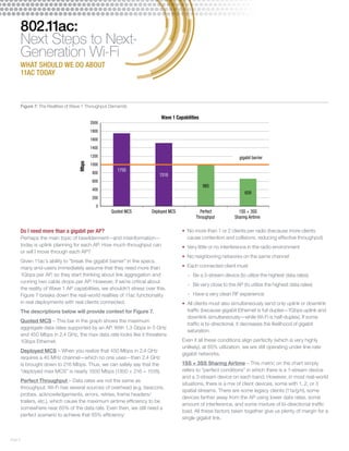
- While 802.11ac advertising emphasized higher maximum speeds enabled by wider channels and more streams, the document notes many real-world networks see limited gains from these features due to interference and client limitations.
- The first generation of 802.11ac provides improved silicon and modulation over 802.11n but similar maximum streams, while a potential second generation could provide additional streams and support for multi-user MIMO.