Characteristic Comparison of U-Shaped Monopole and Complete Monopole Antenna
Antenna types
1. 5. ANTENNA TYPES
Antennas can be classified in several ways.
One way is the frequency band of operation.
Others include physical structure and
electrical/electromagnetic design. The
antennas commonly used for LMR—both at
base stations and mobile units—represent
only a very small portion of all the antenna
types.
Most simple, nondirectional antennas are
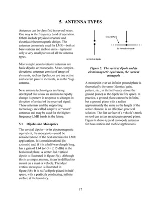
basic dipoles or monopoles. More complex, Figure 5. The vertical dipole and its
directional antennas consist of arrays of electromagnetic equivalent, the vertical
elements, such as dipoles, or use one active monopole
and several passive elements, as in the Yagi
antenna. A monopole over an infinite ground plane is
theoretically the same (identical gain,
New antenna technologies are being pattern, etc., in the half-space above the
developed that allow an antenna to rapidly ground plane) as the dipole in free space. In
change its pattern in response to changes in practice, a ground plane cannot be infinite,
direction of arrival of the received signal. but a ground plane with a radius
These antennas and the supporting approximately the same as the length of the
technology are called adaptive or “smart” active element, is an effective, practical
antennas and may be used for the higher- solution. The flat surface of a vehicle’s trunk
frequency LMR bands in the future. or roof can act as an adequate ground plane.
Figure 6 shows typical monopole antennas
5.1 Dipoles and Monopoles for base-station and mobile applications.
The vertical dipole—or its electromagnetic
equivalent, the monopole—could be
considered one of the best antennas for LMR
applications. It is omnidirectional (in
azimuth) and, if it is a half-wavelength long,
has a gain of 1.64 (or G = 2.15 dBi) in the
horizontal plane. A center-fed, vertical
dipole is illustrated in figure 5(a). Although
this is a simple antenna, it can be difficult to
mount on a mast or vehicle. The ideal
vertical monopole is illustrated in
figure 5(b). It is half a dipole placed in half-
space, with a perfectly conducting, infinite
surface at the boundary.
17
2. Figure 7. Omnidirectional base-station
antennas
Figure 6. Typical monopole antennas for
(a) base-station applications and (b) mobile
applications
5.2 Base-Station Applications
For base-station installations (where an
omnidirectional pattern is desired), there are
two practical implementations of the vertical
dipole. The first type is the sleeve antenna,
as illustrated in figure 7(a). The sleeve
antenna is a vertical dipole with the feed
(transmission line) entering from one end of
a hollow element. The second type is a
monopole over a ground plane, as illustrated Figure 8. A monopole antenna horizontal-
in figure 7(b). The monopole in this illustra- plane pattern, base-station application. The
tion uses a set of four wire elements to uniform maximum gain corresponds to the
provide the ground plane. Figure 8 shows a outer line on the polar plot
typical pattern for a base-station monopole.
A variation of the dipole antenna is the
folded dipole as shown in figure 9. Its
radiation pattern is very similar to the simple
dipole, but its impedance is higher and it has
a wider bandwidth.
18
3. Many of the vehicular antennas at VHF
high-band are quarter-wave monopoles. At
150 MHz, this would mean that a whip
antenna, approximately 0.5 m (1.5 ft) long,
is needed. Half-wave and 5/8 wave
monopoles also are used, but they require
Figure 9. A folded-dipole antenna some sort of matching network (i.e.,
inductors and/or capacitors) in order to
match the antenna impedance to that of the
5.2.1 Mobile Applications transmission line. These longer antennas
have a gain of approximately 3 dBi.
Nearly all vehicular antennas are monopoles
mounted over a (relatively) flat body surface
At UHF, a quarter-wave whip is
(as described above). In this application, the
approximately 15 cm (6 in) long. Since this
monopole is often called a “whip” antenna.
length is physically small, some design
At VHF low-band, a quarter-wave monopole
considerations can be used to increase the
can be 2.5 m (approximately 8 ft) long.
gain. For example, as shown in figure 10(b),
However, an inductor (coil) at the base of a
two 5/8 wave monopoles can be “stacked”
monopole adds electrical length, so the
with a phasing coil between them. This is,
physical length of the antenna can be
effectively, an antenna array (see sec. 5.5)
shorter. Although this kind of “loaded”
that provides a gain of approximately 5 dBi.
antenna will appear to be a quarter-wave
antenna, it will have a gain value somewhat
At 800 MHz, a quarter-wave monopole does
less than a true quarter-wave monopole. This
not perform well, so the approach of
disadvantage can be somewhat offset,
stacking two monopoles, with a phasing coil
however, by the ability to mount the
between, is used. Such an antenna,
(shorter) antenna in the center of a surface
illustrated in figure 10(c), looks much like a
that will act as an acceptable ground plane
mobile cellular phone antenna and has a gain
(e.g., the roof or trunk of the vehicle).
of approximately 3 dBi.
Figure 10(a) shows an illustration of this
kind of antenna.
The azimuthal pattern of all monopoles is
ideally a circle. In other words, the gain
versus azimuth angle in the horizontal plane
is constant. In practice, the pattern in the
horizontal plane generally is not
omnidirectional, since the portion of the
vehicle used as a ground plane is not
symmetric, and usually there are other
obstructions. Figure 11 shows the horizontal
plane pattern for an 840 MHz whip located
Figure 10. Typical mobile antennas in the center of the roof of a vehicle [13].
The dotted line in the figure shows the
effects, on the pattern, of a law-enforcement
19
4. light bar mounted on the roof ahead of the
antenna.
Figure 13. A typical corner-reflector
antenna
This antenna has moderately high gain, but
Figure 11. A mobile antenna horizontal- its most important pattern feature is that the
plane pattern [13] forward (main beam) gain is much higher
than the gain in the opposite direction. This
is called the front-to-back ratio and is
5.3 Corner Reflector evident in the pattern shown in figure 14.
An antenna comprised of one or more dipole
elements in front of a corner reflector, called
the corner-reflector antenna, is illustrated in
figure 12. A photograph of a typical corner
reflector is shown in figure 13.
Figure 14. A corner-reflector antenna
horizontal-plane pattern
Figure 12. Corner-reflector antennas 5.4 Yagi
Another antenna design that uses passive
elements is the Yagi antenna. This antenna,
illustrated in figure 15, is inexpensive and
effective. It can be constructed with one or
20
5. more (usually one or two) reflector elements antenna can be mounted to support either
and one or more (usually two or more) horizontal or vertical polarization and is
director elements. Figure 16 shows a Yagi often used for point-to-point applications, as
antenna with one reflector, a folded-dipole between a base station and repeater-station
active element, and seven directors, mounted sites.
for horizontal polarization.
Figure 17. A Yagi antenna horizontal-
plane pattern
Figure 15. The Yagi antenna — 5.5 Log-Periodic
(a) three elements and (b) multiple
A somewhat novel, but very useful, design is
elements
the log-periodic antenna. This antenna is
based on the dipole element. As shown in
the illustration of figure 18, it is in fact
comprised of a set of dipoles, all active, that
vary in size from smallest at the front to
largest at the rear. Usually, this antenna is
constructed so the antenna terminals are
located at the front (on the shortest dipole).
Figure 19 shows a typical installation. The
key features of this antenna are, first of all,
its broadband nature, and second, its
relatively high front-to-back gain ratio. The
Figure 16. A typical Yagi antenna latter feature is evident in the typical
radiation pattern shown in figure 20.
Figure 17 is a typical pattern for a three-
element (one reflector, one active element,
and one director) Yagi antenna. Generally,
the more elements a Yagi has, the higher the
gain, and the narrower the beamwidth. This
21
6. 5.6 Arrays
An antenna array (or array antenna) is,
much like it sounds, several elements
interconnected and arranged in a regular
structure to form an individual antenna. The
purpose of an array is to produce radiation
patterns that have certain desirable
characteristics that a single element would
Figure 18. A log-periodic antenna
not. A stacked dipole array, as shown in
figure 21, is comprised of vertical dipole
elements.
This dipole array has an omnidirectional
pattern like the element dipole does; but has
higher gain and a narrower main lobe
beamwidth in the vertical plane. Figure 22
shows how the vertical-plane gain of the
dipole element can be “enhanced” by
making an array of them. Figure 22(a)
represents the radiation pattern of one
element. Figure 22(b) is the pattern of two
elements, and figure 22(c) is for three
elements.
Figure 19. A typical log-periodic antenna
Figure 20. A log-periodic antenna
horizontal-plane pattern
22
7. This is called a binomial or collinear array
[14]. As the number of elements is
increased, the gain increases and the
beamwidth decreases.
The omnidirectional coaxial collinear
antenna (often referred to as an “omni”) is a
very popular array design for base stations. It
is comprised of quarter-wave coaxial
sections with inner and outer conductors
transposed at each junction.
A conceptual illustration is shown in
figure 23. Although more complex than the
illustration, this antenna array behaves like a
series of vertical dipoles stacked one above
the other. The more stacked sections, the
Figure 21. A typical vertical array using greater the gain and the narrower the vertical
folded dipoles beamwidth. A vertical-plane pattern for this
type of antenna is shown in figure 24.
Variations in electrical design can produce a
downward tilt of the vertical-plane pattern as
shown in figure 25. This antenna often is
enclosed in a fiberglass sheath, called a
radome, and appears as a simple pole that
can be mounted off the side or on top of a
mast or tower.
Figure 22. Vertical-plane radiation
patterns for (a) single half-wave dipole,
(b) two-element array, and (c) three-
element array
23
8. Figure 24. A vertical-plane radiation
pattern without “tilt”
Figure 23. A coaxial collinear array
As with all antennas, the array is frequency-
dependent. The gain, directivity, and
radiation pattern are each a function of
frequency. Some antennas will work well
only for the design frequency, and their
performance will degrade as the operating
frequency is separated from the design
frequency. Figure 25. A vertical-plane radiation
pattern with 8/ “tilt”
5.7 Unusual Antennas
The simplest aperture antenna is the slot
There are many other antenna types. Most of
antenna, which is equivalent to a dipole. As
these are beyond the scope of this report, but
shown in figure 26, it is a long, narrow
knowledge about some may be useful for
opening with terminals located at the middle
LMR users.
of the long sides of the slot. This simple slot
and more complex versions are well-suited
While not as commonplace as wire or rod
to covert operations. They can be located on
antennas, aperture antennas are by no means
a vehicle surface and concealed behind a
unusual. These antennas are implemented as
cover of thin insulating material. Slot
an opening in a relatively large, conductive
antennas are common on aircraft and
(metal) surface.
missiles.
24
9. 5.8 Active Antennas
An active antenna is one that contains some
electronic circuitry that can amplify a
received signal at the antenna and thus avoid
interference that may enter the system at the
transmission line. Figure 27 shows this
concept. The antenna “element” is connected
to the input of an amplifier. The output
terminals of the amplifier are the antenna
terminals for this active antenna. The
antenna element and the amplifier are
included in the “active antenna,” shown as a
dashed box in the figure.
Figure 26. A slot antenna
Not so much antenna types as antenna
features, broadband and multiband antennas
are the result of design efforts to make an
antenna perform well over a wide band of
channels. There may be a trade-off in
making an antenna broadband, such as a
reduction in gain or an increase in physical
size. The usual design goals for this type of
antenna are to make the gain and radiation Figure 27. A simple active antenna
pattern, as well as the terminal impedance,
Another purpose of an active antenna is to
relatively constant over the frequency range
transform an unusual antenna terminal
of operation. The log-periodic array is an
impedance to a constant value that matches
example of a broadband antenna.
the characteristic impedance of the
transmission line. This function is useful for
Multiband antennas are designed to operate
some antenna designs in which a specific
on several bands, for example, at both VHF
pattern feature is desired, but cannot be
high-band and UHF. These antennas often
achieved without causing the antenna to
involve clever designs where one part of the
have an unusual terminal impedance. An
antenna is active for one band, and another
active antenna is nonreciprocal and cannot
part for a different band. Again, there will be
be used for transmitting.
compromises. The antenna may have lower
average gain or may be physically larger
5.9 Diversity Antennas
than an equivalent single-band antenna.
Diversity is a technique that improves
reception of radio waves by taking
advantage of the fact that signals that vary
with time (e.g., fading) are not the same at
separated locations. In other words, the
25
10. fading of a signal may be quite different for Adaptive antennas extend the concept of
two locations separated by as little as one diversity another step further. These
wavelength. To take advantage of this, two antennas usually incorporate more than just
antennas, separated by some distance, are two elements (i.e., individual antennas) in
used to receive the same signal. Of the two the array. An adaptive antenna can modify
signals, the one with the highest signal level, its radiation pattern (within limits) in real
at any given time, is automatically sent to time to ensure that the main lobe points in
the receiver. This process is only useful for the direction of greatest signal level.
reception. The electronics required for this Alternatively (or, possibly, simultaneously),
kind of signal processing are sometimes part the same technique can be used to point a
of the antenna system. null in the direction of an unwanted,
interfering signal.
26