Download to read offline


![11
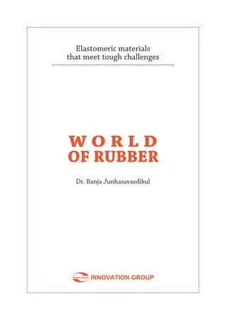
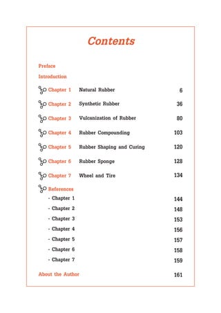
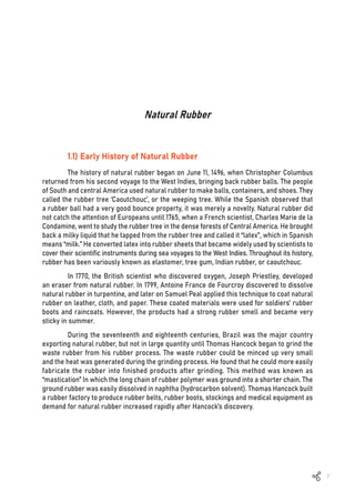
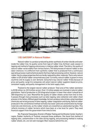
Thailand is the world’s largest natural
rubber producer, with the production at 4.6
million metric tons per year. Indonesia is the
second largest producer, producing 3 million
metric tons per year, followed by Malaysia,
India, Vietnam, and China [1]. The total worldwide
production of natural rubber is around 13 million
tons with 75% produced in three countries i.e.,
Thailand,Indonesia,andMalaysia[2].Agricultural
researchers in Malaysia and Thailand have
worked hard to develop a rubber tree with
highly resistant to the “Toura” fungus that
spreads easily in rubber trees. They have also
studied how to get rubber trees to produce
high yields of rubber latex. They even went
back to the Amazon to collect seeds from para
rubber trees to bring back to their research
laboratories.
The average lifespan of a rubber tree is about 35 years. It takes 6-7 years before
a tree can be tapped for latex. After about 25 years, the trees produce less and less latex,
and they are then cut down and new trees are planted. The wood from para rubber trees is
useful and can be treated with chemicals and used for furniture. In the early morning when
the internal pressure of the tree is high, the farmers extract latex from rubber trees by using
sharp knives to cut away small pieces of bark. Trees are usually tapped on alternate days, but
during the summer when the leaves fall, farmers do not tap latex for 2 months. Latex, which
contains 25-30% dry rubber, slowly drips from the tapping cut for 3-4 hours and is collected
in a small container placed underneath the cut. The collected latex is transferred to a larger
container and carried back to the farmer’s home where it is cleaned by filtering through a
mesh screen and diluted with mineral-free water to 15% solid content in a coagulation tank.
Formic acid is added to the latex while stirring, until the pH of the solution reaches 4-5. At
this acidity, the latex coagulates and is left in the tank for another 4-5 hours. Then water is
squeezed out from the coagulant by using a two roll mill to form 5 millimeters wet rubber
sheets thick which are then dried in the sun for a few days before being sent to the rubber
smoking house where rubber sheets are dried at 60°C for 3 days. Hot air in the smoke house
comes from burning dry wood, and then hot air is pumped into the smoking room. Dried
smoked rubber sheets are pressed into 102 kilograms/bale. The product from this process
is called “ribbed smoke sheet (RSS)” which is widely used in tire manufacturing [3]. The
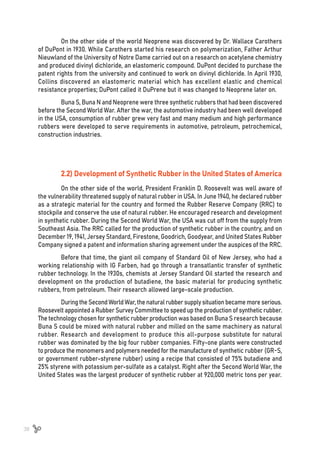
complete manufacturing process of RSS is shown in Figure 1.1](https://image.slidesharecdn.com/worldofrubber-2022-dr-220920074909-7d531796/85/World-Of-Rubber-13-320.jpg)
![12
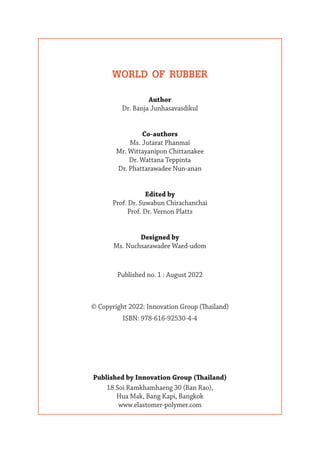
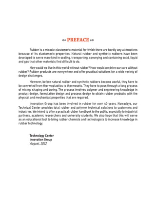
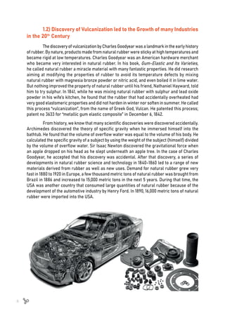
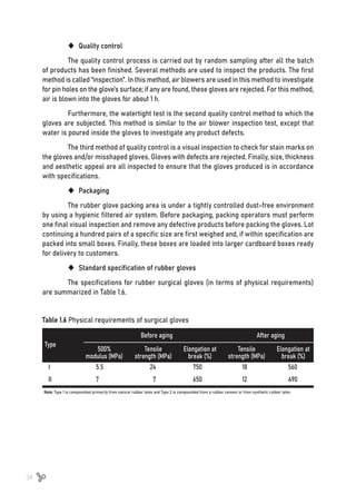
There are other processes to produce clean dry rubber. Instead of using hot air
from burning wood, hot air from burning liquefied petroleum gas (LPG) gives clean “air dried
sheet.” Block rubber is another type of dry rubber that is used to make colored rubber
products; small pieces of chopped wet rubber from the coagulation tank are dried in an oven
for 24 hours at 70°C as recommended by the Rubber Research Institute of Thailand (RRIT)
[4]. Besides dry rubber, natural rubber latex is used to produce rubber tubes, sheeting, film,
and dipped goods such as rubber gloves and condoms. Products from natural rubber latex
tend to be clean and have the excellent physical properties in terms of elongation, tear
resistance, and recovery. Natural latex is normally supplied to latex product factories as
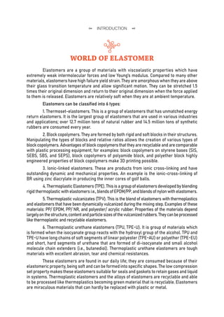
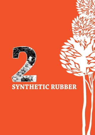
60% dry rubber content (%DRC). The process for concentrating latex is simple as illustrated
in Figure 1.2. Fresh latex is centrifuged to obtain a 60% concentration which is known as
concentrated latex. Ammonia is added to the concentrated latex to adjust pH to higher than
10, and sometimes chemicals, such as methyl tuods (TMTD) and zinc oxide (ZnO), are also
added as preservatives [5]. Then, the concentrated latex is shipped in liquid form to factories,
where it is used for dipping, coating, and other products. Today, people who are routinely
exposed to rubber products, such as healthcare workers and medical doctors, often develop
an allergic reaction after the routine contacts with the products. Therefore, surgical and
examination gloves are alternatively made from synthetic latex such as chloroprene latex
and nitrile butadiene rubber latex (NBL) and are more acceptable as allergic-free products.
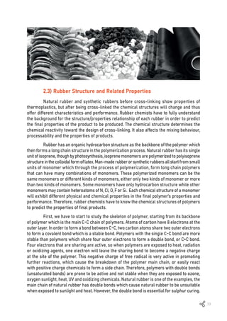
Figure 1.1 Manufacturing process of ribbed smoke sheet (RSS).](https://image.slidesharecdn.com/worldofrubber-2022-dr-220920074909-7d531796/85/World-Of-Rubber-14-320.jpg)
![13
By nature, natural rubber has a very high molecular weight and contains small
amounts of proteins and enzymes. During storage, the protein and phospholipid contents of
the rubber, which makes the rubber harder [6, 7]. Therefore, to soften the rubber, it is
necessary to shorten the polymer chain at the beginning of the mixing process by “mastication,”
the mechanical shearing of the natural rubber between rollers inside the mixer
[8]. This process results in the reduction of the molecular weight and Mooney viscosity
(a measurement named after American physicist, Melvin Mooney) of the rubber, allowing
compounding ingredients to be easily mixed into the rubber. Sometimes special chemicals
(peptides) such as aromatic mercaptans (i.e., sulphur containing compounds) are added to
natural rubber at the beginning of the mixing process to reduce mastication time and to
achieve a constant Mooney viscosity. In order to manufacture natural rubber with consistent
quality, a small amount of the mercaptan additive is added during the coagulation step to
produce natural rubber with constant Mooney viscosity.
Because of the four electrons in the cis-1,4-isoprene double bonds in natural rubber,
chemical reactions are easily activated. This is the reason why natural rubber can be
vulcanized with sulphur at the positions of the double bonds. However, these double bonds
can also be activated by UV radiation, other chemicals, and heat, thus causing natural rubber
to have poor resistance to deterioration from those sources. Scientists have improved the
quality of natural rubber by creating epoxidized natural rubber. The epoxidized natural rubber,
with different percentages of epoxide group is commercially available with more higher price
than the natural rubber.
1.5) Natural Rubber: Structure and Function
In 1963, Karl Ziegler and Giulio Natta shared the Nobel Prize in Chemistry for the
development for their eponymous catalyst for the production of stereoregular polymers from
propylene. The catalyst of organoaluminum compounds coupled with a transition metal. This
led to the development of synthetic rubber with a structure to that of natural rubber. But the
structure of natural rubber, which is known to be provenance of nature’s enzymatic control,
could not be duplicated by synthetic pathway because of the unique structure of natural rubber.
Figure 1.2 Concentrated latex supply chain](https://image.slidesharecdn.com/worldofrubber-2022-dr-220920074909-7d531796/85/World-Of-Rubber-15-320.jpg)
![14
Natural rubber is a long chain polymer that contains repeated units of isoprene as a
result of a series of biochemical reactions starting form isopentenyl pyrophosphate within the
tree [9]. Natural rubber has very high molecular weight which results in less chain ends and
more entanglement than an equal weight of synthetic rubber [10]. The chain ends are weak
points at the molecular scale, because they do not transmit the strength of covalent bonds in
the molecular chain. Therefore, tensile strength is high for high molecular weight polymers
like natural rubber. In general, microstructural characteristic related to the branching lead to
a decrease of glass transition temperature (Tg) of a polymer. Natural rubber has these large
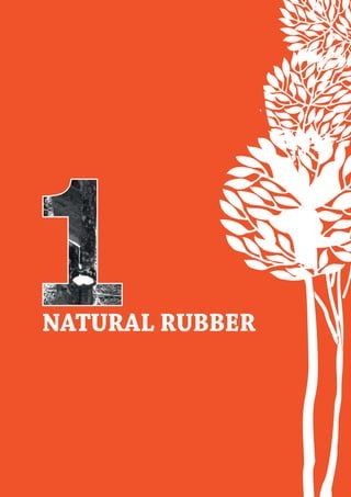
bulky groups of branched chains, thus causing the Tg of natural rubber to be as low as -72ºC.
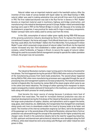
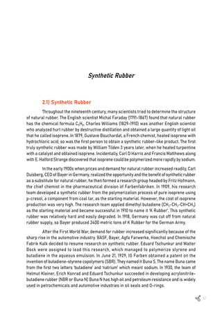
As the microstructure of natural rubber, consists almost entirely of cis-1,4 polyisoprene
(Figure 1.3) [11], it is very stereoregular and confers many of the mechanical properties.
Crystallinity of natural rubber is a characteristic provided by this microstructure. If the units
of polymer chain are in a regular enough for spatial arrangement, the interactions between
units i.e., hydrogen bond, hydrophilic-hydrophilic or hydrophobic-hydrophobic, including
ionic-interaction among functional groups will lead to the crystalline structures which stiffen
the polymer. Because of stereo regularity, natural rubber form crystals upon storage (rubber
becomes harder after a period of storage) causing some processing difficulties and upon
stretching. The reversible crystallization upon stretching, ‘strain induced crystallization’,
which is caused by intermolecular forces in the polymer, provides many unique properties,
especially in excellent green strength, tensile strength, building tack, cut resistance, tear
resistance, cut and crack growth [12, 13]. These properties of find natural rubber are very
useful in tire applications.
1.6) Strain Induced Crystallization of Natural Rubber
Low-temperature performance of rubber is determined not only by the presence of
Tg, but also the presence of crystallinity. Polymers may show crystallization upon cooling of a
homogeneous melt, if the polymer chain (partially) aligns in an exothermic process. Melting is
an exothermic process occurring at the characteristic melting temperature with the enthalpy
released being a direct measure of the degree of crystallization. For crystallization formation,
the loss in entropy from the increased order has to be overcome by a sufficiently large gain
in the enthalpy. The present of crystallization in polymer results in a much higher modulus
and rigidity and a lower toughness, i.e., in the less rubbery behavior. In NR, isoprene rubber
(IR), butadiene rubber (BR), nitrile rubber (NBR), butyl rubber (IIR) and chloroprene rubber
(CR), the crystallization occurs significantly.
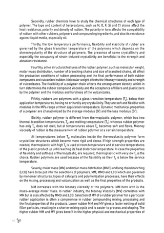
Figure 1.3 Chemical structure of cis-1,4-polyisoprene from natural rubber [11]](https://image.slidesharecdn.com/worldofrubber-2022-dr-220920074909-7d531796/85/World-Of-Rubber-16-320.jpg)
![15
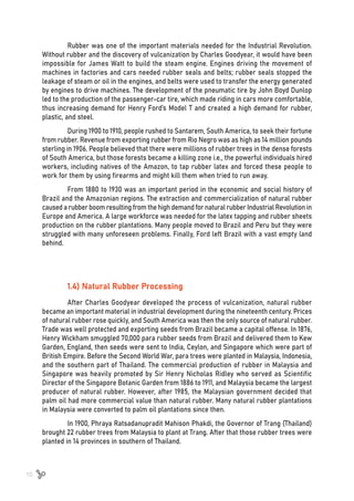
Strain-induced crystallization (SIC) may occur
for highly stereoregular rubber with melting temperature
below room temperature, such as IR, IIR, CR, and
especially NR [14]. At high strain levels, the polymer chain
aligns, which facilitates crystallization [15]. Stretching the
rubber chain results in a shift of melting temperature, to
temperature above the room temperature. The crystalline
regions formed result in self-reinforcement of the rubber
as evidenced from the higher tensile strength and
elongation at break. Natural rubber is renowned for its
high degree of SIC and its excellent ultimate properties
[15, 16].
Because of the resilience of natural rubber after
cross-linking upon curing, the elasticity and flexibility,
combined with crystallization induced toughness when
stretched. This mean less kinetic energy is lost during
repeated stress deformation. In tires, natural rubber is
used extensively to provide low heat build-up. For instance,
the shoulder temperature of heavy-duty truck tires may
rise up to 100ºC, and the heat of this magnitude increased the risk of a blow-out or other
delamination related to crock growth. Tremendous stresses also occur on the tread and
sidewall of the truck tire if it backs up over the curb, causing strain in the sidewall.
Besides hydrocarbons, natural rubber contains approximately 6% non-rubber
components (i.e., 2.2% protein and 3.4% lipid and other substances). It was found that these
small amounts of non-rubber also exhibit crystallization effects and affect associated
properties [17, 18]. In conclusion, it is difficult to replace natural rubber with synthetic rubbers
in tire applications.
1.7) Composition of Natural Rubber Latex
Although many species of plants are found to exude NR latex (NRL) on tapping, only
‘Hevea Brasiliensis’ plant is of commercial importance and accounts for 99% of World’s NR
production. NRL is mainly consists of rubber molecules as the major fraction and other
fraction called as non-rubber components such as protein, lipid, carbohydrate, etc. as
summarized in Table 1.1 [19, 20]. These rubber and non-rubber components may vary due to
various factors such as season, weather, soil and especially rubber clone [19, 21]. Some of
these components are suspended and dissolved in the aqueous phase of the latex, while
the others are adsorbed on the rubber surface of rubber particles. It is noted that 5% of
non-rubber components can be removed or degraded during dry rubber processing [20].](https://image.slidesharecdn.com/worldofrubber-2022-dr-220920074909-7d531796/85/World-Of-Rubber-17-320.jpg)
![16
1.8) Rubber and Mastication
The very high molecular weight of natural rubber results in less chain ends and more
entanglement than equal weight of synthetic rubber. Its Mooney viscosity varies from type of
rubber tree, fertilizer used, season of rubber tapping and especially staging time. Its viscosity
affects rubber breakdown during plasticization which in turn affects the mold filling condition
in finished product production. In tire production, natural rubber has to be masticated to obtain
the required Mooney viscosity before the rubber compounding step. Mastication is a polymer
chain breakdown process which is related to mechanical breakdown at low temperature and
a thermo-oxidative effect at high temperature [8, 22, 23] as shown in Figure 1.4.
Latex
%w/v fresh latexa
%w/w dry matter of latexb
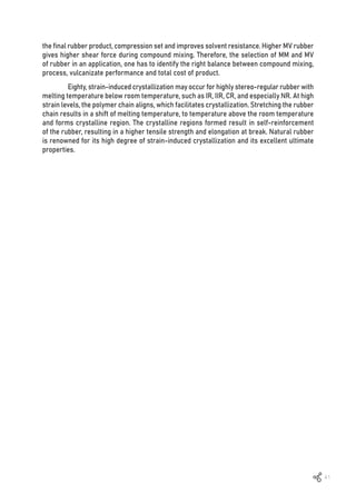
Figure 1.4 The effect of mastication in variation of temperature [22]
Table 1.1 Composition of NRL [20]
Composition
Rubber hydrocarbon 35.0 84.0
Lipids 1.3 3.2
Protein 1.5 3.7
Carbohydrate 1.5 3.7
Organic substances
0.5 1.1
Inorganic substances 0.5 1.2
a
Averaged from data published by Wititsuwannakul, D.; Wititsuwannakul, R. In Biopolymers. Vol. 2:Polyisoprenoids; Koyama, T., Steinbüchel,
A., Eds.; Wiley-VCH: Weinheim, 2001; pp 151–201.25
b
Calculated.](https://image.slidesharecdn.com/worldofrubber-2022-dr-220920074909-7d531796/85/World-Of-Rubber-18-320.jpg)
![17
Figure 1.5 The reactions for the mastication of natural rubber [23]
The first effect occurs during low temperature shearing in the internal mixer (<80ºC).
The long-chain branched networks do not have time to relax and break by the reaction of
stresses, therefore, the shorter chain molecules are formed and the viscosity decreases [23,
24]. The rate of emission of heat depends upon the distribution of both shear and elongation
stresses, as well as the nature of the polymer and the temperature, the natural of polymer,
and the temperature. When the temperature increases, the polymer chains are more mobile
resulting in the decrease in relaxation time. The higher temperature, the lower the effect of
mechanical breakdown. The second effect is thermo-oxidation breakdown. This chemical
oxidative reaction happens when the temperature of mastication increases beyond 80ºC.
As consequence, the radicals species (R*) are form [25]. These free radicals react with
oxygen to form proxy radicals (ROO*) followed by transforming to be a cyclic diperoxide
or hydroperoxide group (ROOH). As a consequence of the hydrogen atom abstraction, the
free radicals are formed along the chains to propagate the chain rupture (Figure 1.5), as
described in the previous work [23].
The use of peptizing agents can accelerate the breakdown of natural rubber polymer
chains. The peptizing agents act by the mechanochemical and thermo-oxidative breakdown
of natural rubber as radical acceptor at low temperatures and as oxidation catalysts at high
temperature [23]. Peptizing agents usually are compounds of thiophenol or aromatic disulfides
combined with metal complexes of Fe, Cu, and Co as the catalysts for the oxidative breakdown.
1.9) Latex Compounding Technology
Latexes (or latex compounds) are complex colloid systems containing polymer
molecules as the major fraction. The polymer may be a homo-polymer or co-polymer
(random/ block/ graft) having stereo regularity with complexity related to the polymer chains
i.e., linear, branched and molecular weight distribution of the latex depend on the grade of
selected. Latex is rubbery or resinous in nature while the rubber molecules in the latex can
be cross-linked, plasticized and oil extended. The type of latex lead to the different mechanical
properties and temperature limits of serviceability [26]. The rubber particles is generally oval
with the particle size less than 5 micron under a typical distribution. The aqueous phase
consists of dissolved and suspended matter and the information about the concentration and
pH are essential for successful latex compounding. Latex products are subject to degradation,
therefore, an adequate antioxidant protection is necessary.](https://image.slidesharecdn.com/worldofrubber-2022-dr-220920074909-7d531796/85/World-Of-Rubber-19-320.jpg)
![18
1.9.1 Preservation of NR latex
(I) High ammonia NR latex (HANR latex)
NR Latex causes coagulation within a few hours due to acidity through micro-organisms,
and the pH of latex decreases to roughly 5.0. Ammonia at a concentration of 0.7-1.0% is mostly
used for long term preservation [26], but it also serves as a latex bactericide and sequestering
agent for Mg2+
and PO4
3-
ions.
The weak points of using ammonia are from its strong odor, the additional cost,
including the thickening when compounded with ZnO which, interferes the gelation of latex
foam while further compounded with sodium silicofluoride (SSF). Therefore, the excess
ammonia has to be driven off before compounding.
(II) Low ammonia NR latex (LANR latex)
Centrifugation is used to generate low ammonia NR latex (or LA-TZ) which is then
preserved with low ammonia coupling with other preservatives such as tetramethylthiuram
disulphide (TMTD) and zinc oxide (ZnO). With 0.025% TMTD/ZnO and 0.05% of ammonium
laurate on latex, the ammonia level is less than 0.29% [26]. The LA-TZ latex is commonly used
in all dipped products application.
Zinc dialkyl dithiocarbamates i.e., zinc dimethyldithiocarbarmate (ZDMC) and
zinc diethyldithiocarbarmate (ZDEC), at 0.1-0.2 % concentration along with 0.2% ammonia and
0.2% lauric acid enhance the stability of NR latex to be in the similar level as 0.7% ammonia
preserved latex without any significant effect on vulcanization [26]. However, the latex may
discolor badly on aging, in some cases, the color develops from the trace amount of copper
contamination, so-called (copper staining).
For other types of low ammonia latex, the latex is preserved with a low ammonia
content (about 0.2%) and 0.2% boric acid coupling with 0.05% lauric acid, which is a common
LA-preservative system [26]. The benefits of LA-TZ latex are its ease of use, low cost, low
toxicity and free from discoloration. However, the un-vulcanized deposits tend to soften more
quickly.
Low ammonia latex can also be preserved by coupling 0.2% sodium
pentachlorophenate with 0.2% ammonia as a stabilizer [26] although this method is not
widely used due to toxicity of the stabilizer which is linked to pentachlorothiophenol.](https://image.slidesharecdn.com/worldofrubber-2022-dr-220920074909-7d531796/85/World-Of-Rubber-20-320.jpg)
![19
1.9.2 Destabilization of latex or gelation
Chemical methods (acidification, addition of salts of polyvalent metals, higher
concentration of salt) and mechanical methods (mechanical agitation and dehydration) can
both destabilize NR latex. Destabilization produces that generate homogenous destabilization,
also known as gelation, of a three-dimensional aggregate of rubber particles. The NR latex
has good gel strength that most suitable for latex applications and foamed products, though
excessive stabilization results in weaker gels and slower gelation rate. Gels do not have a
consistent composition (or structure), and the film shrinks due to aqueous phase exudation,
which is retained in the interstices of the gel.
Three methods of Gelation [26]
(I) Organic acid/acids or acid liberating substances
(II) Use of salts of multivalent cations
(III) Application of heat
(I) Gelation By Acids
Rubber particles are stabilized as a result of the net negative charge (from both
lipids and protein structure on the surface of rubber particles) which creates repulsive
forces between rubber particles. The pH of latex is dropped once acid is added, resulting in
a decrease in the ionization of adsorbed anions and a decrease in repulsive forces between
rubber particles, resulting in gelation.
(II) Gelation by Salts
Normally, calcium nitrate is used in the dipping process to create gels of the
compounded latex on the ‘formers’. Calcium ions destabilize the latex by forming insoluble
salts with all fatty acid soaps and protein solution. Calcium ions also produce a high
concentration of ions, reducing the colloidal stability of NR latex.
(III) Heat sensitized gelation
Immersing a hot former in to a suitably heat sensitized latex compound is knowns
as heat sensitized gelation. Zinc amine ions and hydrophilic polymers can both help to heat
sensitize NR latex [27]. Zinc oxide-ammonium salt process (ZOA) facilities the role of ammonia
solutions to increase the solubility of zinc ions [26]. The addition of an ammonium salt also
increases the ionic strength of the aqueous phase and contribute to destabilization. Because
the gelation occurs at room temperature in a short period, the ZOA process is truly heat
sensitive. However, heat accelerates the process. The gelling time or the thickness of dipped
product can be used to determine the degree of heat sensitization. The thickness of the dry
film is influenced by a number of processing parameters such as temperature of the former,
rate of immersion, dwell time and heat capacity of the former including the compounding
latex characteristics [27].](https://image.slidesharecdn.com/worldofrubber-2022-dr-220920074909-7d531796/85/World-Of-Rubber-21-320.jpg)
![20
1.9.3 Film formation and structure
Formation of film involves immobilization of free-moving polymer particles when
brought into contact. In most latex-goods manufacturing processes, the contact between
polymer particles is achieved by the ‘gelation’ process as a consequence of pH dropping with
ammonia stabilizer during the initial stages of drying. Note that if the pH is maintained by
using a fixed alkali stabilizer like KOH, this process will not proceed. Gelation does not affect
the rate of drying of the film or any other characteristics.
Beforedrying,thefilmisleachedwithcleanwatertoremovewater-solublechemicalin
compoundingresiduesfromthecompoundingprocess,aswellasresidualcoacervant(i.e.,aqueous
calcium nitrate) and other surface-active substances [26]. This improves the film’s feel,
eliminates porosity defects and makes it resistance to water absorption and aging. The film
thickness of dipped goods varies between 0.1 mm to 0.2 mm depending on the viscosity of
the latex compound, a multi-dip process is used to achieve the necessary film thickness.
1.9.4 Chemical modification of NR latex
(I) Pre-vulcanized natural rubber (PVNR) latex
PVNR latex is a chemically modified NR latex, which on drying gives a vulcanized
film, and can be produced latex stage with concentrated latex (or HANR latex). During the
maturation process, the PVNR latex compounds containing ZnO and ultra-fast accelerators
(i.e., ZDBC or ZDEC) and other ingredients usually achieve some degree of pre-vulcanization.
The formulation of produced PVNR latex is prepared as follows [26]:
In the jacked mixing tank, the HANR latex and ingredients are mixed with stirring.
When the desired degree of cross-linking has been achieved, the latex is heated up to
50°C-60°C by flowing hot water through the jacket for 3-5 hr or when QC the QC tests
confirmed the as-desired of cross-linking. The latex compound is cooled to room temperature,
then filtered or collected.
The degree of cross-linking of latex compounds is determined by swelling method,
combinedsulphuranalysisortensilepropertyevaluation[28].PVNRlatexispopularinthemedium/
Compounding Ingredients
60%HANR latex 100 167
50% ZnO dispersion 1 2
50% ZDEC dispersion 1 2
50% Sulphur dispersion 2 4
10% KOH Solution 0.3 3
10% Sodium Caseinate 0.2 2
Dry
(by weight)
Wet
(by weight)
Table 1.2 Compounding ingredients of PVNR latex](https://image.slidesharecdn.com/worldofrubber-2022-dr-220920074909-7d531796/85/World-Of-Rubber-22-320.jpg)
![21
Figure 1.6 Poly(methyl methacrylate)-grafted-natural rubber (Heveaplus MG) [30]
smallsectordippedproductbecauseisdoesnotnecessaryorislimitedtoincorporatethepigments
such as balloons, medical product and feeding bottle teats. The cross-linking can be achieved
by reaction with sulphur, sulphur donors (i.e., dithiodimorpholine (DTDM), tetraethylthiuram
disulfate (TETD) and tetramethylthiuram disulfate (TMTD)) or by gamma radiation. The
compounding formulations can be varied to be suitable for the application. ZnO is not
necessaryif ZDEC/ZDBC is present. ZnO reduces the film clarity but it be substituted by ZnCO3
to improve the clarity. For peroxide cross-linking, tert-butyl hydroperoxide and tetraethylene
pentamine are used. Maximum film clarity is obtained by using ZDBC alone. The cross-links
found in the pre-vulcanized latex are predominantly polysulphidic (except for sulphurless /
sulphur donor cures).
(II) Heveaplus MG graft polymers
Poly(methyl methacrylate)-grafted-natural rubber (Heveaplus MG) grafted side
chains of polymethyl-methacrylate on NR molecule [29] as shown in Figure 1.6.
The polymethyl-methacrylate used are 15% (MG15), 30% (MG30) and 49% (MG49) [31].
As the amount of polymethyl methacrylate in MG increases, their capacity to form declines.
This form of latex can be blended in any proportions with unmodified latex. The modulus,
tensile strength and tear strength of such blends are significantly improved. When methyl
acrylate is partially substituted with butyl methacrylate in the grafting reaction, the film
forming properties improve [29, 31].](https://image.slidesharecdn.com/worldofrubber-2022-dr-220920074909-7d531796/85/World-Of-Rubber-23-320.jpg)
![22
(III) Hydroxylamine modified latex (HRH latex)
Because of the cross-linking process, the viscosity of the concentrated latex increases
during storage. During the first 20-30 days, the rate of storage hardening is faster (and over
100 days the process is completed). When hydroxylamine is added for 0.15 at the latex
production stage; the storage hardening effect is inhibited [32]. The vulcanizates show slightly
low modulus (resulting in less volume shrinkage of latex foam), whereas other properties
are unchanged. This type of latex is used to make latex foam and latex adhesives for use in
footwear [26].
1.9.5 Latex compounding ingredients
The transformation of wet NR latex into a final product is accomplished using various
processes, which are based on the criteria of minimum energy consumption during various
stages (High energy consumption during drying has been a major concern).
In all the processes, a stable colloidal system is maintained for a desired time after
which the system is made unstable to convert the same to a solid product. Maintaining the
balance of stability is the major challenge.
The latex compounds contain four or more distinct dispersed phases and are highly
polydispersed with several different surfactants. The aqueous phase of high ionic strength
gives the NR latex compounds a relatively low colloid stability but facilitate conversion to
solid products. For dipped goods, the latex compounds used must produce continuous films
on the former and maintain film integrity during drying and vulcanizing stages.
No. Function
1. Vulcanizing agents Sulphur, Sulphur donors & others.
2. Accelerators Dithiocarbamates, Thiazoles, Thiurams,
Xanthates
3. Antioxidants Amine derivatives, Phenolic derivatives.
4. Fillers & pigments Inorganic, Organic.
5. Surface-active agents Anionic, Cationic, Amphoteric, Non-ionogenic.
6. Viscosity modifiers Plant hydrocolloids, Proteins, Polyvinyl alcohols,
Cellulose derivatives, Starches, Polyacrylates,
Carboxylate polymers, Colloid clays, etc.)
7. Other ingredients: Mineral oils, Waxes, Resins, Antifoaming agents,
Antiwebbing agents, Corrosion inhibitors, etc.
Ingredients
Table 1.3 Latex compounding ingredients](https://image.slidesharecdn.com/worldofrubber-2022-dr-220920074909-7d531796/85/World-Of-Rubber-24-320.jpg)
![24
1. Thai rubber farmers do not have sufficient knowledge in rubber plantation.
2. They lack knowledge and good practice in tapping latex and how to collect clean
latex to deliver to rubber drying plants.
3. In the rubber processing plant, is operating in fully manual process and there is
no quality control system etc.
Ms. Preprame set up standards and educated these farmers how to produce good
latex to supply to rubber plants so they could produce consistent quality rubber sheets
supply to the market. She wrote a handbook of ‘How to produce rubber smoked sheet’ and
enhance it to the agricultural standard (TAS 5906-2013) [33] and a handbook in producing
crepe rubber in the following five years (TAS 5907-2018) [34]. Those handbooks’ contents are
related to the process of Good Agricultural Practice (GAP) and Good Manufacturing Practice
(GMP) to encourage good practice by rubber farmers in their farms, latex tapping, collecting
and delivery to rubber plants. In the rubber processing plants, GMP guides them how to have
good manufacturing practices to produce consistent rubber sheets. She also provides
standards in the process of producing good quality latex (TAS 5908-2019) [35], cup-lump
rubber to supply to the rubber plants (TAS 5910-2020) [36] and excellent latex collection
centers (TAS 5911-2021) [37].
Innovation Group realizes the value that Ms. Preprame Tassanakul produces by GAP
and GMP programs and gives strong support to GAP and GMP programs.
1.10.1 What is GAP?
Good agricultural practice (or GAP) is good practice in rubber plantation [35].
1. Land to plant rubber trees: Owner must have the legal right on those lands (not
from the deforested area). The suitable planting area is the tropical monsoon area with
average rainfall 1,250 mm per year, pH in soil in the range of 4.5-5.5
2. Hazardous chemicals and herbicides are not allowed to be used.
3. Starting from clones of rubber tree that are recommended by Rubber Authority
of Thailand. Rubber trees to tap latex must be mature, rubber trees must have a minimum
circumference of 50 cm and height not less than 1.5 meter from the ground level.
4. Tapping latex by barking half of the circumference of a rubber tree with an angle
of 30-35 degrees. Tapping should be done 2 days and stop 1 day or in a dry period or the dry
areas, tapping should be done 1 day and stop 1 day (alternate days). This should be done after
the mid-night till 6 o’clock in the morning.
5. Collection of latex should be done and delivered to the process plant, not over 8
hours after tapping.
6. Equipment to use; latex cups and containers for collecting latex have to be kept
clean and avoid any contamination from unwanted material.
7. Filter the latex from latex cups into the stainless steel container with 7 mesh-filters.
8. Record quantity of latex collected every time as a production statistic.
9. Clean rubber cups and place upside down, every time after collecting the latex, to
prevent contamination of foreign material.](https://image.slidesharecdn.com/worldofrubber-2022-dr-220920074909-7d531796/85/World-Of-Rubber-26-320.jpg)
![25
1.10.2 What is GMP?
Good manufacturing practice (or GMP) is the instructions on good manufacturing
practice in rubber plants [37].
1. Condition of rubber plant: it should have a proper design and construction according
to standards of processing plant with good utilities.
2. Stainless steel is recommended to be used in the latex receiving station and the
coagulation tank.
3. Every arriving latex batch is required to go through standard quality control.
4. Arriving latex must pass through filtration with 10 mesh-filters.
5. Take a sample of each arriving lot and check dry rubber content (DRC) to calculate
weight of formic acid to use. Only formic acid is used in rubber coagulation (adding 4% by
weight of formic acid to 100 parts DRC).
6. Check volatile fatty acid number (VFA no.) of latex accordingly to ISO 506
7. Stainless steel coagulation tank is recommended.
8. Squeeze water out from the sponge sheets by a clean two roll mill. Dry those
sheets under the shade before sending to the smoking room.
9. Smoke rubber sheets at a controlled temperature of 55-60ºC for 3 days.
10.Packthesheetinplasticbagsof25or30kilograms/pack(accordingtotherequirement
of customers)
1.10.3 Benefits of GAP/ GMP
1. Good properties control: dirt, ash content, volatile materials and has a good initial
Mooney viscosity range.
2. Contamination free
3. Traceability of rubber sheet, right from original plantation.
4. Easy to handle (a 30 kilograms/bale instead of a 110 kilograms/bale) and power free.
5. Non-hazardous chemicals.
6.Themostimportantarehigheryield,betterproduct,andfarmerscansellatahigherprice.
GAP and GMP are good standard practices in producing consistent quality of natural
rubber. However, this needs cooperation from rubber farmers in practicing GAP/GMP standards.](https://image.slidesharecdn.com/worldofrubber-2022-dr-220920074909-7d531796/85/World-Of-Rubber-27-320.jpg)
![26
1.11) Value Chain of Natural Rubber
Natural rubber is one of the strategic agricultural products of the country. Thailand is
the largest rubber producer harvesting 4.2 million tons each year involving 1 million families
in the upstream industry of natural rubber. However, natural rubber has a very long value
chain. In order to develop a sustainable growth of natural rubber, we have to consider how
to create values to this total value chain. The total value chain of rubber can be divided into
three sectors:
1. Upstream industries involve the growers and tappers. This has to add value to primary
production of rubber latex or basic dried rubber sheet, such as cup lump, scrap raw sheet and
crepe rubber. Starting from diagram 1, there are 1 million families or approximately 6 million
of the Thai population living in rubber plantations and working in the upstream industries.
2. Intermediate or midstream industries may be called rubber processors. They
produce rubber on plantations and convert it into semi-finished products, such as ribbed
smoked sheet rubber (RSS), standard Thai rubber (STR) (or block rubber) and concentrated
latex
3. Downstream product industries produce various rubber products and latex dipped
goods
Over 85% of Thai intermediate rubber (dried rubbers and concentrated latex) is
exported. The main importing countries of Thai intermediate rubber are China (58%), Malaysia
(15%) Japan, and Korea. The main use of rubber sheet is for the production of tires (about
49%) followed by latex dipped goods (13%). Natural rubber supply is largely impacted by
market pricing, which is mainly set up by buyers, China, Singapore and Japan. Because the
price setting by buyer markets is done irrespective of production costs, artificially low prices
disincentivize producers from sustainable production and replanting, further compromising
the supply of natural rubber. Meanwhile two international organizations, Forest Stewardship
Council (FSC) and Global Platform for Sustainable Natural Rubber (GPSNR) are becoming
influencers to the manufacturing and marketing of natural rubber. In order to sustain growth
of natural rubber, the Rubber Authority of Thailand should support upstream and midstream
of natural rubber to qualify for FSC and GPSNR certification.
Figure 1.7 Total supply chain of natural rubber (NR) [38]](https://image.slidesharecdn.com/worldofrubber-2022-dr-220920074909-7d531796/85/World-Of-Rubber-28-320.jpg)
![27
1.11.1 Global platform for sustainable natural rubber (GPSNR)
The GPSNR is an international, multi-stakeholder, voluntary membership driven
platform for improvements in socioeconomic and environmental performance of the natural
rubber value chain by defining and implementing industry wide standards on fairness, equity
and environmental sustainability. The development of the GPSNR was initiated by the CEO’s of
the World Business Council for Sustainable Development (WBCSD) and Tire Industry Project
(TIP) in 2018. The members of the platform include tire manufacturers, rubber suppliers,
rubber processors and vehicle makers. The GPSNR policy frame works are composed of 8
sustainable natural rubber principles, [39]:
Commitment to legal compliance, forest sustainability, respect human rights,
community livelihoods, increase production efficiency, traceability and management, systems
and processes to drive effective implementation of policy, and reporting [40].
1.11.2 Forest stewardship council (FSC)
FSC is an independent, not for profit, non-governmental organization established to
support environmentally appropriate, socially beneficial, and economical management of the
world’s forest. To achieve the mission of FSC, the FSC has developed a set of 10 principles
as follows [41]:
Commitment to legal compliance, respect worker and human rights, enhancing the
social and economic well-being of local communities, indigenous peoples’ rights, benefits
from the forest, environmental values and impacts, management planning, monitoring and
assessment, forest conservation, implementation of management activities [41].
1.11.3 How to apply the FSC trademark in the finished goods
Chain of custody certification (COC) of any company which is the process to ensure
that all the processes or transformations of FSC-certified products have been checked at
every processing stage (Traceability system) [42].
Remark: FSC certification applies to plantation owners. COC certification applies to
manufacturers, processors and traders of FSC-certified forest products.](https://image.slidesharecdn.com/worldofrubber-2022-dr-220920074909-7d531796/85/World-Of-Rubber-29-320.jpg)
![28
1.12) Rubber Gloves
In 1894, William Stewart Halsted, the first chief of surgery at Johns Hopkins Hospital,
invented surgical gloves for his wife as he noticed her hands were affected by the daily
operations she performed and in order to prevent medical staff from developing dermatitis
from surgical chemicals [43]. In 1965, Ansell Rubber Co. Pty. Ltd. developed the first disposal
medical gloves. Nowadays, over 300 billion pairs of rubber gloves are consumed every year
and demand remains high for medical gloves that protect against virus [44]. USA, Europe and
Japan consume 60% of the rubber gloves produced. Malaysia is the largest glove manufacturer,
accounting for 63% of the total world production. Although, Thailand has the main source of
raw materials, Thailand produces only 18% of the world’s glove market. China is the third
highest producer at 10%, while others such as Indonesia, Belgium and Vietnam share 9% [44].
The major materials in producing rubber gloves are natural rubber (NR) latex,
acrylonitrile latex, neoprene latex, isoprene latex and polyvinyl chorine latex. The main reason
why people use rubber gloves is to protect their hands from contacting fluid when they are
performing an operation; for example: household gloves are used by housewives in their
daily works, washing, cooking and gardening. Household gloves protect their hands from
detergents, contact with food and soil during their operations and NR latex or chloroprene
gloves are widely used. Industrial gloves such as latex gloves protect workers from contact
with chemicals, but NBR (nitrile) or chloroprene gloves, which have oil and chemical
resistances, are the preferred gloves. Surgical gloves need good resistance to fluids and
have good permeability resistance; therefore, chloroprene gloves are preferred. Medical and
examination gloves, which are consumed in very large quantities are typically made the areas
of nitrile and NR latex. However, the highest demand for disposal gloves; they are vital goods
in the healthcare environment. They not only protect healthcare providers and patients from
potentially harmful microorganisms, but they also assist set a standard for hygiene and care
in the business. Different materials and design choices make certain products better suited
for different medical environments. Nitrile, NR and vinyl latex are most common material
used in disposable gloves. For decades, NR latex gloves have been used as the medical
disposable gloves worldwide, because they had been recommenced for protection since 1980
against blood borne pathogens like HIV. Disposable gloves have to be comfort, able have a
high degree of touch sensitivity and be relatively cheap. NR latex gloves were most popular
until it was found that many people were allergic to the NR latex. Vinyl gloves are prepared
by using PVC liquid, as a petroleum-based material. The advantage of vinyl gloves is their
low cost, but they are less durable than NR latex gloves and have limited protection against](https://image.slidesharecdn.com/worldofrubber-2022-dr-220920074909-7d531796/85/World-Of-Rubber-30-320.jpg)
![29
biomedical exposure. Nitrile gloves came into prominence in the market in the 1990s as the
leading rubber gloves, being the ideal choice for disposable gloves because they have
exceptional puncture-resistance and are not allergenic to human skin.
Figure 1.8 Market demand and trend–overall NR vs NBR gloves [44-46]
1.12.1 Overview of the global glove market
In 2020, Thailand emerged as the world’s second largest rubber gloves manufacturer
and exporter behind Malaysia. Thailand exported over 20.5 billion pairs of rubber gloves, an
increase of approximately 22% from the same period the previous year due to the Covid-19
outbreak [44]. According to EIC, Thailand earned approximately 700 million USD per year from
glove exports, while Malaysia’s earned more over 1 billion USD per year from rubber glove
product exports [39]. Malaysia imports concentrated latex from Thailand in order to manufacture
rubber products (i.e., glove, condom, glue and pharmacy products). However, Malaysia
produces rubber products for domestic consumption as well as export to other countries on
the international market [47]. Malaysia’s gain could be viewed as Thailand’s economic loss,
as Thailand lack the ability to transform concentrated latex into a valued-added product [44].](https://image.slidesharecdn.com/worldofrubber-2022-dr-220920074909-7d531796/85/World-Of-Rubber-31-320.jpg)
![30
Figure 1.9 Market demand and trend – by Segmentation [48]
Product (1) Latex glove (1) Nitrile glove (I) enhancing the concen trated latex
(2) Nitrile glove (2) Latex glove producers into the rubber glove market
(II) improve the drawback of NR product
(i.e., reducing-proteins)
Manufacturers Not many Various The support from Thai government and
manufacturers (i.e., manufacturers (i.e., the related rubber industry
only 1 manufacturer 4 manufacturers
among 5 largest among 5 largest
manufacturers 2021) manufacturers2021)
Efficiency 6-7 million gloves/ 20 million gloves/ Increased advanced technology for
(glove/month) month (type on month (based on faster and higher production capacity
different number different number
of factories) of factories)
Export market Mostly exported to Mostly exported to Extend distribution to new markets (i.e.,
USA,anapproximate USA,andapproximate Asia Pacific, South-East, Middle East
rate 36% rate 33% and Africa), due to lower price of latex
glove and lower number of proteins-
allergic cases
Rubber glove
industry
Strategic adjustment
of Thailand
Thailand Malaysia
Table 1.4 Thailand’s and Malaysia’s rubber gloves industries comparison [44, 47]](https://image.slidesharecdn.com/worldofrubber-2022-dr-220920074909-7d531796/85/World-Of-Rubber-32-320.jpg)
![31
Figure 1.10 Comparison of latex glove and synthetic gloves (i.e., nitrile and vinyl gloves)
1.12.2 Types of rubber gloves
Rubber gloves are protective items to cover the hands of the wearer and provide
physical protection for the wearer. There are two main categories of rubber gloves by material;
namely, (I) latex glove and (II) synthetic gloves (i.e., nitrile and vinyl gloves). In addition,
rubber gloves can be classified into two types: (I) medical and (II) non-medical gloves. The
market is divided into end-user industries such as healthcare, food and beverage, automotive,
machinery, and others. The key information for the two major categories of rubber glove by
materials are illustrated in the figure below:
1.12.3 Rubber glove manufacturing processes
Rubber glove manufacturing processes are normally comprised of seven steps: (I)
raw material testing, (II) compounding, (III) dipping, (IV) leaching and vulcanizing, (V) stripping,
(VI) quality control, and (VII) packing [49-51]. These process steps are shown in the figure
below:](https://image.slidesharecdn.com/worldofrubber-2022-dr-220920074909-7d531796/85/World-Of-Rubber-33-320.jpg)
![32
‹ Raw material testing
Before the latex compounding process, raw materials are tested in the factory’s
laboratory, where materials are subjected to various detailed and stringent quality tests (i.e.,
latex and chemical properties testing).
‹ Latex compounding
Ingredients and their functionalities for rubber glove manufacturing
processes are summarized in Table 1.5 [51]. All ingredients are generally mixed with latex (i.e.,
concentrated latex, HANR latex) such as surfactant or stabilizer, activator, accelerators,
antioxidants, and vulcanizing agent (i.e., sulphur) based on the specified formulation. Before
being fed to the production line, the compounded latex is tested to ensure that it meets the
specification requirements.
Figure 1.11 Rubber glove manufacturing process model [52]](https://image.slidesharecdn.com/worldofrubber-2022-dr-220920074909-7d531796/85/World-Of-Rubber-34-320.jpg)
![33
60% HANR latex 100.0
10% KOH 0.30
20% K-laurate 0.20
50% ZnO 0.40
50% Wing stay L 0.75
50% ZDC 0.75
40% SDBE 0.50
50% Sulphur 0.50
Total 103.40
Ingredients phr
Table 1.5 Rubber formulation of rubber glove (surgical glove) [50, 51]
‹ Dipping
Before forming the gloves on glove molds (or formers), cleaning and dipping
processes of the rubber glove molds are required. Firstly, the rubber glove molds are cleaned
with acid (i.e., H2SO4 or HCl) or alkali (i.e., NaOH or KOH) to remove contaminant and dust,
followed by leaching with clean water, and then dried at 50ºC. After that, the glove molds are
dipped into the coagulant tank (i.e., the mixed solution of CaNO3 or CaCl2 and CaCO3), which
contains a processed chemical.
Next, the glove molds are then dipped into the latex dipping tank to coat them with
a thin layer of latex. Coagulant and compound latex tanks are both controlled for properties
and conditions such as total solid content (%TSC) and temperature, and so on.
‹ Leaching and vulcanizing
The gel films on rubber glove molds are beaded, further dried, and then leached in
the pre-leached tank before they are further vulcanized to provide good physical properties
and reduce moisture content.
In the leaching step, all gloves are moved through a water bath to leach excess additives
from previous stages (i.e., coagulant and other ingredients) and reduce protein content. The
effectiveness of this process is dependent on three major factors: (I) the temperature of the
water, (II) the duration of the process, and (III) the rate of water exchange.
In the vulcanizing step, the latex film is vulcanized by the combination of sulphur
and accelerator generating cross-linking of the rubber molecules while being heated (i.e., 100-
120ºC); this provides high elasticity and good tensile strength to the rubber film.
‹ Stripping
In this step, the leached gloves are dipped into a closely controlled wet-slurry tank
to remove any protein buildup, including, bacterial and other contaminants which remain on
the rubber glove. Finally, auto-stripping lines are used to remove the gloves from the formers.](https://image.slidesharecdn.com/worldofrubber-2022-dr-220920074909-7d531796/85/World-Of-Rubber-35-320.jpg)
![35
1.12.4 Future & market trend of rubber glove
Although demand for rubber gloves varies by product, continued growth in demand is
possible against a background of rising hygiene and safety consciousness among consumers.
The following significant shifts in disposable gloves demand have occurred in recent years [53]:
ƒ HighdemandforsyntheticglovesduetotheriskoftypeIhypersensitivityinlatexglove
ƒ More light weight or less thickness of rubber glove (especially in NBR glove)
ƒ Ease of working while wearing gloves
ƒ More sustainable production of degradable gloves
COVID-19 health workers use approximately 80 million gloves per month, but the
synthetic material from which they are primarily made is disposed of in landfill for 100 years.
However, latex gloves can biodegrade 100 times faster than the synthetic glove and produce
30% less waste during production [54]. This has resulted in more sustainable and green ways
of life; slowly but steadily, everything is shifting towards biodegradable products.
Previous works has reported the potential of biodegradable natural rubber latex
gloves for commercialization. It was found if a new green additive was included in the NRL
gloves formulation to accelerate the biodegradation process, the biodegradable gloves could
be decomposed in soil in four weeks [55]. Therefore, a special formulation of latex glove
(more biodegradable material) is an ideal future composition for sustainable manufacturing,
providing a greener future to benefit everyone.](https://image.slidesharecdn.com/worldofrubber-2022-dr-220920074909-7d531796/85/World-Of-Rubber-37-320.jpg)
![42
2.4) Neoprene or Chloroprene Rubber
Neoprene is a trade name of DuPont for this excellent weather, ozone, chemical
corrosion and oil resistant synthetic rubber. In 1934, DuPont announced its success in
developing chloroprene rubber through the emulsion polymerization process. DuPont called
it neoprene [1]. The construction of a 2000 tons/year plant was completed in 1940, providing
the first synthetic rubber used by the US military during the Second World War.
In 1957, Bayer produced Perbunan C (chloroprene rubber) by a continuous production
process. The first commercial production of Denka chloroprene with a capacity of 200 tons/
month was established in 1962. On November 4, 2005, Denka announced its acquisition of
DuPont chloroprene Rubber, which made Denka the largest chloroprene supplier.
Chloroprene is the common name for 2-chloro-1,3-butadiene with the formula
CH2=CCl-CH=CH2 [2]. Acetylene was used as a feed stock in the older manufacturing process,
while the modern processes use butadiene. By 1980, most of the chloroprene was produced
from butadiene in the USA and Western Europe, while in Japan, Denki-Kagaku still used the
acetylene route. Acetylene came from the production of calcium carbide and its dimerization
to form mono-vinylacetylene in the aqueous hydrochloric acid solution of CuCl2 and NH4Cl at
80ºC in the reactor tower. Then chloroprene was formed by a direct hydrochlorination step,
a process that needed high investment and was very energy intensive. The more recent
chloroprene process is based on butadiene, a less expensive feedstock. The initial step is a
gas-phase free-radical chlorination with chlorine at 250ºC and 1-7 bar to give a mixture
of 3,4-dichlorobutene and 1,4-dichlorobutene. Step 2 is the isomerization and de-hydro
chlorination of 3,4-dichlorobutene-1, followed by treatment with base to induce
dehydrochlorination to 2-chloro-1,3-butadiene in the last step of the process [3]. The
dehydrochlorination entails loss of a hydrogen atom in the carbon 3 position and chlorine
atom in the carbon 4 position, therefore a double bond between carbon 3 and 4 is formed.
Currently, the polymerization of chloroprene is a free-radical polymerization in an emulsion
process which allows good temperature control of the reaction and is a stable process [3].
This leads to better batch-to-batch control of variations in structure and rheological
properties of grades of chloroprene produced.
2.4.1 Structures and properties
Chloroprene has four different chemical structures, 1,4-trans, 1,4-cis 1,2 and 3,4 in
the polymer chain as shown in Figure 2.1 [2, 4]. The composition of these types of polymer
which determines the grade of chloroprene is dependent on the reaction temperature. Lower
polymerization temperature, produces a higher yield of 1,4-trans incorporation as resulting
in higher crystallization rate of the polymer. Grades of chloroprene from low temperature
polymerization are needed for adhesive applications benefiting from strain-induced
crystallization. More grades of 1,4-cis incorporation are produced at higher temperatures for
various grades elastomeric properties.](https://image.slidesharecdn.com/worldofrubber-2022-dr-220920074909-7d531796/85/World-Of-Rubber-44-320.jpg)
![43
Figure 2.1 Chemical structure of chloroprene rubber [2, 4]
The high chlorine content with its high density of 1.23 g/cc [4] and mid-range polarity
makes chloroprene inherently fire resistant and gives moderate fluid swelling resistance.
Although chloroprene has an unsaturated polymer backbone, the chlorine atom which is
attached to the tertiary carbon atom of the double bond, withdraws electrons from the
unsaturation in the backbone. This chlorine atom reduces the reactivity in oxidation reactions
of chloroprene, therefore chloroprene, in spite of the double bond in its structure, offers
a reasonable resistance to weathering, ozone and heat. The high amorphous grade of
chloroprene has very low glass transition temperature of -40ºC to be an excellent rubber
for low temperature applications [4]. Chloroprene also has high green strengths, high tear
resistance and overall good mechanical and excellent dynamic properties [4].
Generally, the grades of chloroprene offered by DuPont, (acquired by Denka) Arlanxeo,
and Denka, can be separated into three groups [5].
1. Adhesive grades which have high crystalline structure are offered in different
Mooney viscosities. As a consequence of crystallization, the adhesive strength of the adhesive
film is considerably greater than the amorphous grades of chloroprene.
2. Chloroprene grades which have more 1,4-cis give amorphous structures; various
Mooney viscosities are offered. For extrusion applications, a small quantity of pre-crossing
agent is added to the polymer to provide good extrusion processing [5].
3. Chloroprene grades with sulphur from the peptisation process contain polysulphide
bridges, giving unique properties [5]. They have high initial viscosity allowing faster and better
filler dispersion. These compounds are good for the extrusion and calendaring process. They
also promote good bonding between rubber and substances such as fabric.](https://image.slidesharecdn.com/worldofrubber-2022-dr-220920074909-7d531796/85/World-Of-Rubber-45-320.jpg)
![44
Structures of G type and W type are shown in Figure 2.2 and 2.3, respectively.
Presence of chlorine atoms in the backbone of chloroprene rubber make its
properties as follows [4, 7]:
1. Chloroprene is resistant to non-polar oil such as paraffinic and naphthenic oil, but
swells in aromatic and engine oil.
2. Chlorine atoms in chloroprene can help to provide flame resistance.
3. Chloroprene is resistant to oxidation and ozone.
4. Chloroprene can be self-scorching at high temperature. This is because
chloroprene releases HCl to react with metal oxide in the compound.
5. Chloroprene rubber has poor dielectric resistance.
Adhesive
AD
none Low to high rapid Fast crystallization
AG
Sulphur Medium slow Rheological control
W polymer
W
none 42-51 fast General purpose
WHV 100
none 90-105 fast General grade
medium Mooney
viscosity
WRT
2,3-dichloro- Medium very slow
Low temperature app.
WD 1,3-butadiene High very slow High viscosity WRT
GRT
containing S Medium medium High tear
GW
Co-monomer Mooney Viscosity Crystallization rate
Distinguishing
Features
Type
Table 2.1 Grades of Neoprene offered by DuPont [6]
Figure 2.2 G type: contains sulphur in the structure
Figure 2.3 W type: contains chlorine atom in the structure](https://image.slidesharecdn.com/worldofrubber-2022-dr-220920074909-7d531796/85/World-Of-Rubber-46-320.jpg)
![45
Figure 2.4 Vulcanization of chloroprene rubber by the action of zinc oxide and magnesium
oxide [10]
2.4.2 Applications
Because of its high crystalline structure in the adhesive grades, chloroprene finds
application in solvent adhesives [7, 8]. In the moulded rubber area, chloroprene is well
recognized for its high gum vulcanized strength due to the strain-induced crystallization.
It has good chemical stability, excellent weathering and ozone resistance [4], and good thermal
resistance properties which it can retain at low temperatures. It has excellent dynamic
propertiesandgoodgaspermeabilityresistance[8].Itisconsideredforageneral-purposerubber
goods produced by molding, extrusion and calendaring. Chloroprene is self-extinguishing
hence it has been used in high power-cable jacketing and mining belt applications. Because
of its excellent dynamic property, Neoprene GRT is also used in V belts. Neoprene WRT and
WD are used in bridge bearing pad, wiper blade and seal joint [8]. Neoprene W finds its
applications in general rubber applications, such as industrial hoses, axle boots, wire and
cable jacketing, engine mountings and bearing pads. Neoprene GRT and GW types have
excellent tear resistance, soft touch feeling and are used in sport wet-suit applications.
Neoprene latex finds its application in industrial and surgical glove applications.
2.4.3 Vulcanization of chloroprene
Chloroprene is generally vulcanized by metal oxides; the common cross-linking
agent is usually zinc oxide, along with magnesium oxide which is necessary to give scorch
resistance [9]. The reaction involves the allylic chlorine atom, which is the result of the small
amount of 1,2 polymerization, as shown in the chemical reactions below (Figure 2.4):
Metal oxide vulcanization with accelerated-sulphur vulcanization is common.
Tetramethylthiuram disulphide (TMTD), N, N’-di-o-tolyguanidine (DOTG) and sulphur are
commonly used for high resilience and good dimensional stability, while metal oxide with
ethylenethiourea (ETU) is a curing system being used to avoid carcinogens.](https://image.slidesharecdn.com/worldofrubber-2022-dr-220920074909-7d531796/85/World-Of-Rubber-47-320.jpg)
![46
2.5) Styrene-butadiene Rubber (SBR)
Styrene-butadiene rubber (SBR) is a general purpose synthetic rubber, produced
from a copolymerization of styrene and butadiene
Figure 2.5 Chemical structure of SBR [2]
Exceeding all other synthetic rubber in consumption, SBR is used in large quantities
in automotive and truck tires. It is the most consumed type of synthetic rubber, widely used
in place of natural rubber because of its good abrasion resistance. However, because of the
butadiene content, SBR become swollen and weakened by hydrocarbon oil and is degraded
over time by atmospheric oxygen and ozone.
2.5.1 History of styrene butadiene rubber
SBR was developed and commercialized in Germany in 1930 with the name of Buna S.
It was produced by emulsion polymerization which contained 68-70% butadiene and 30-32%
styrene. Around 1942, GR-S (Government rubber styrene) was produced in the United States.
The product was designed to be similar to the German Buna S but lower in molecular weight
for easier processing. It was also polymerized by emulsion polymerization. Immediately
after the Second World War, the United States was the largest producer of synthetic rubber
at 920,000 metric tons per year.
2.5.2 Polymerizations of styrene butadiene rubber
SBR can be produced either by emulsion polymerization (E-SBR) or solution
polymerization (S-SBR) techniques which lead to different properties. Emulsion SBR can be
produced by both hot and cold polymerizations. Hot emulsion SBR has more branch chains
than the cold emulsion SBR, which makes it better for extrusion, be more stable and have less
shrinkage. Cold SBR is more abrasion resistant and has higher tensile strength. The S-SBR
was developed with higher molecular weight and a smaller molecular weight distribution.
S-SBR has better flexibility and tensile strength with lower rolling resistance than E-SBR.
Therefore, S-SBR finds its application in tire manufacturing.
In E-SBR, there are two processes, hot polymerization and cold polymerization. The
polymerization temperature of E-SBR hot polymerization is 50ºC or higher, while the cold
is about 5°C or even lower (-10°C or -18°C). In the cold polymerization process, more active
initiators are used. Cold polymerization gives better controlled structures, such as less
branching which will give better abrasion resistance and higher tensile strength (E-SBR
hot polymerization produces more branching which makes it better for extrusion and less
shrinkable). Cold polymerized E-SBR is more popular in the market than hot polymerized
E-SBR.](https://image.slidesharecdn.com/worldofrubber-2022-dr-220920074909-7d531796/85/World-Of-Rubber-48-320.jpg)

![48
Emulsion Grades
Krylene 1500 23.5 16 12 72 -50 0
Krylene 1502 23.5 16 12 72 -50 0
Krylene 1509 23.5 16 12 72 -50 0
Krynol 1712 23.5 16 12 72 -50 27
Krynol 1721 40.0 16 12 72 -35 27
1st
Gen’ Solution Grades
Buna SL 704 Bayer 18.0 10 38 52 -75 0
Buna SL 705 Bayer 24.0 10 38 52 -65 0
Buna SL 750 Bayer 18.0 10 38 52 -75 27
Buna SL 751 Bayer 25.0 10 38 52 -65 27
Buna SL 754 Bayer 18.0 10 38 52 -70 33
2nd
Gen’ Solution Grades
Buna VSL 1924 S25 Bayer 25 33 25 42 -50 0
Buna VSL 1939 S20 Bayer 20 50 19 31 -45 0
Buna VSL 1940 S20 Bayer 20 50 19 31 -40 27
Buna VSL 1944 S15 Bayer 15 53 18 21 -50 0
Buna VSL 1945 S15 Bayer 15 53 18 29 -50 27
Buna VSL 1950 S25 Bayer 25 67 13 21 -25 27
Buna VSL 1954 S25 Bayer 25 73 10 17 -20 0
Buna VSL 1955 S25 Bayer 25 73 10 17 -20 27
Styrene
content (%)
Microstructure of 100% BR
Vinyl content
(%)
Cis-1,4
content (%)
trans-1,4
content (%)
Tg (°C) Oil (%)
Grade
Table 2.3 Microstructure of some SBR grades [11]
High aromatic oil (HA oil) was added to the SBR in the past. HA oils contain high
concentrations of polycyclic aromatic hydrocarbons (PAH) which have been identified as
carcinogenic. In 2010, European Legislation controlled extended oils in E-SBR and processing
oil in tire compounding to contain not more than 1 mg/Kg (0.0001% by weight) of Benzo[a]pyrene
and not more than 10 mg/kg (0.001% by weight) of all listed PAH. Currently, treated distilled
aromatic extract (TDAE), residue aromatic extract (RAE), and treated residue aromatic extract
(TRAE) have been used as substitutes for HA oils [12]. SBR grades do not used HA oils now.](https://image.slidesharecdn.com/worldofrubber-2022-dr-220920074909-7d531796/85/World-Of-Rubber-50-320.jpg)
![49
Table 2.4 Grades of emulsion styrene-butadiene rubber (E-SBR)
Buna@ SE 1500 Caxias (BR) 23.5 52 none - staining in bales
Buna@ SE 1502 H Triunfo (BR) 23.5 53 none - non-staining in bales
Buna@ SE 1502 L Triunfo (BR) 23.5 49 none - non-staining in bales
Buna@ SE 1723 Caxias (BR) 23.5 50 TDAE 37.5 staining in bales
Buna@ SE 1739 Caxias (BR) 40.0 53 TDAE 37.5 staining in bales
Buna@ SE 1783 Caxias (BR) 23.5 49 RAE 37.5 non-staining in bales
Buna@ SE 1793 Caxias (BR) 23.5 51 TRAE 37.5 staining in bales
Buna@ SE 1799 Caxias (BR) 40.0 55 TRAE 37.5 staining in bales
Production site
Styrene
(%)
ML
(1+4)
Type of
oil
Oil
(phr)
Physical
form
Stabilization
Name
Table 2.5 Grades of solution styrene butadiene polymer (S-SBR)
Buna@ VSL 4526-2 Pt.Je ́ro ̂me (FR) 26.0 44.5 TDAE 37.5 -30 in bales
Buna@ VSL 4526-2 HM Pt.Je ́ro ̂me (FR) 26.0 44.5 TDAE 37.5 -30 in bales
Buna@ VSL 2538-2 Pt.Je ́ro ̂me (FR) 38.0 25 TDAE 37.5 -31 in bales
Buna@ VSL 2438-2 HM Pt.Je ́ro ̂me (FR) 38.0 24 TDAE 37.5 -32 in bales
Buna@ VSL 3038-2 HM Pt.Je ́ro ̂me (FR) 38.0 30 TDAE 37.5 -26 in bales
Production site
Styrene
(%)
ML
(1+4)
Type of
oil
Oil
(phr)
Physical
form
Tg (ºC)
Name
2.5.4 Compounding and vulcanized properties
SBR compounding is similar to NR compounding but does not require mastication
as the molecular weight is designed to be not too high for mixing and processing. The same
curing ingredients can be used as for NR. However, SBR curing is slower than that for NR so
more accelerator or more active accelerator is required [11]. Also, SBR cannot crystallize on
stretching like NR, therefore it needs reinforcing filler.
Even though most properties of SBR are comparable to NR, some properties are
lower like gum tensile strength, elongation at break, tack, hysteresis and resilience.
However, reinforcing fillers and designed compound formulation can improve these
properties. The better properties of SBR over NR are processability, slightly better abrasion
and aging resistance together with less scorch problems.
2.5.5 Applications
The main applications of SBR are tires and the rest are hoses, belts, adhesives,
footwear, rollers and molded rubber goods. SBR can be used in many applications as a
replacement of NR but not in severe dynamic applications and very low heat build-up. This
is one of the reasons why SBR cannot be substitute for NR in tire manufacturing. However,
blending SBR with NR or BR can improve some properties.](https://image.slidesharecdn.com/worldofrubber-2022-dr-220920074909-7d531796/85/World-Of-Rubber-51-320.jpg)
![50
2.5.6 Other SBR related polymers
Ricon 100, a low molecular weight, liquid copolymer of butadiene and styrene can be
used as polymeric plasticizer having a high vinyl content.
Molecular weight (Mn) QCS-651/ Q 34.03 P019 4,500 g/mol
1,2 Vinyl content* QCS-642/ Q 34.03 P040 70 wt.%
Styrene content QCS-642 20 wt.%
Viscosity @45ºC QCS-630/ Q 34.03 P035 40,000 Cps
Tg QCS-681 -15 ºC
Specific gravity @25ºC QCS-649 0.90 -
Test method Value Unit
Property
Table 2.6 Typical physical and chemical properties [13]](https://image.slidesharecdn.com/worldofrubber-2022-dr-220920074909-7d531796/85/World-Of-Rubber-52-320.jpg)
![51
Figure 2.6 Chemical structure of NBR [14]
2.6) Acrylonitrile Butadiene Rubber (NBR Rubber)
Acrylonitrile butadiene rubber, also known as nitrile rubber (NBR), is a random
copolymers of butadiene and acrylonitrile, as shown in Figure 2.6 [14]. It was developed in
1931 at BASF and Bayer laboratory. Then, IG Farben commercialized NBR rubber in 1935. The
NBR rubber has excellent oil, fuel and acid resistances, this is because of high polarity of
acrylonitrile containing in rubber molecule. Butadiene is the polymer back bone. Because of
unsaturated in butadiene portion, NBR is able to be cured by sulphur and sensitive to UV and
ozone [15]. At higher acrylonitrile (ACN) content, NBR has higher oil resistance and higher
glass transition temperature (Tg). This type of NBR is widely used as oil seals and O-ring
applications.
There are two processes in producing NBR rubber are hot and cold polymerization.
• In hot polymerization, acrylonitrile and various butadiene monomers (1,3-butadiene
and 1,2-butadiene) are reacted in the emulsion (soap phase). The acrylonitrile and butadiene
ratio varies depending on the specific requirements of oil and fuel resistance and low
temperature. For special grade of NBR, it contains a third monomer such as divinyl benzene,
methacrylic acid for providing specific properties. The mixture was reacted at 70ºC for several
hours in the polymerization tank. Dimethyldithipo-carbamate is used to shortstop reaction.
The unreacted monomers are removed through the steam in a slurry stripper. After that, NBR
latex is transferred through a series of filtration and further mixed with antioxidant. Then,
obtained NBR latex is coagulated by calcium nitrate or aluminum sulfate. Finally, the NBR
coagulum is subsequentially washed and dried into crumb rubber.
• In cold polymerization, the process of cold NBR is very similar to hot polymerization.
For cold reaction, it is reacted in the polymerization tanks at 5ºC-15ºC, there are less branching
is generated on cold NBR form.
2.6.1 Properties of NBR
The ACN content, or the ratio of acrylonitrile groups to butadiene groups in main
chain molecules, is a significant property of NBR. NBR has lower Tg at lower ACN content,
while at higher ACN content offers the polymer with improved resistance to nonpolar solvents
[4]. Most applications that require both solvent resistance and low temperature flexibility
require the ACN content approximately 33%. The general properties of NBR is summarized
in Table 2.7 [16].](https://image.slidesharecdn.com/worldofrubber-2022-dr-220920074909-7d531796/85/World-Of-Rubber-53-320.jpg)
![52
Oil, fuel and grease resistance +
Good processing characteristics +
Variety of curing systems +
Good hot air resistance
• Long term: 90ºC
• 40 days: 120ºC
• 3 days: 150ºC
Low permanent set +
Good abrasion resistance +
Low gas permeability +
Moderate to good low temperature flexibility -
Moderate ozone resistance (except NBR/PVC) -
Moderate tack -
Compatibility with polar thermoplastics (i.e., PVC, phenolics) +
Properties
Table 2.7 General properties of NBR [16]
As a consequence of NBR’s special properties, it is widely used in the automotive and
aerospace industries to produce seal, grommets, fuel and oil handling hoses, and self-sealing
fuel tanks, among other things. It is also utilized in the nuclear industry to produce protective
gloves. Because of its operating temperature stability across a wide temperature range
of -40°C to 108°C (-40°F to 226°F), NBR is a desirable material for aerospace applications.
Moreover, NBR is applied in a variety of applications such as sealants, sponges, footwear,
adhesives, expanded foams, and floor mats.
2.6.2 General types of NBR
‹ Cold NBR
The current generation of cold NBRs is available in a wide range of compositions.
The ACN content ranges from 15% to 51%, resulting in a wide range of Mooney viscosity for
raw NBR material ranging from 25 unit to 110 units. A large variety of ingredients, including
emulsifier systems, coagulants, stabilizers, molecular weight modifiers, and chemical
compositions are used in cold polymerization. Third monomers are added to the main chain
of a polymer to improve performance. Each variety serves the unique function.
Cold NBR polymerization also uses continuous, semi-continuous and batch
polymerization. The procedure to polymerize cold polymers [9] uses temperatures ranging
from 5°C to 15°C, depending on the required balance of linear-to-branched structure. Lower
polymerization temperatures result in more linear polymer chains.
‹ Hot NBR
For Hot NBR polymerization, temperatures ranging from 30°C to 40°C are used to
polymerize [9]. This method produces highly branched polymers. Its branching structure](https://image.slidesharecdn.com/worldofrubber-2022-dr-220920074909-7d531796/85/World-Of-Rubber-54-320.jpg)
![53
Figure 2.7 Chemical structure of hydrogenated acrylonitrile butadiene rubber (HNBR)
provide strong tack and binding in adhesive applications. This type’s physically entangled
structure gives greater tear strength than cold NBR polymerization. Furthermore, due of
their natural flow resistance, they are great candidates for compression molding and sponge
processes. Other uses include thin-walled or complicated process (i.e., extrusion) that need
shape retention.
‹ Cross-linked hot NBR
Cross-linked hot NBR is branching polymers that has been further cross-linked by
the addition of a di-functional monomer. This product is frequently used in molded parts to
offer sufficient back pressure or molding forces and to remove trapped air during rubber
processing. Another strategy is to improve shape retention (or dimensional stability) in
extruded and calendering goods. This results in more successful extruding and vulcanization
of intricate shaped parts, as well as release better from calender-rolls. Furthermore, this
form of NBR improve shape retention, impact resistance, and flexibility for modified PVC.
‹ Carboxylated nitrile butadiene rubber (XNBR)
Carboxylated nitrile butadiene rubber (XNBR) is similar to nitrile rubber, but the
polymer backbone contains a terpolymer composed of nitrile, butadiene and monomers
which contains carboxyl groups such as methacrylic acids, which drastically accelerates
cure characteristic [17, 18]. This material offers higher tensile and tear strengths, as well as
better abrasion, as compared to normal NBR grade [17]. As a result, XNBR rubber is typically
used in dynamic parts such as seals and rod wipers [19].
‹ Bound antioxidant NBR
The network-bound antioxidant NBR grade is available with an antioxidant polymerized
with butadiene and acrylonitrile [16, 19]. This NBR grade’s objective to improve the aging
resistance of normal NBR grade by modifying the polymer itself [17]. Furthermore, the polymer
bound with antioxidant improves the water and oil resistance for the NBR vulcanizate [21].
‹ Hydrogenated nitrile butadiene rubber (HNBR)
Hydrogenated nitrile butadiene rubber (HNBR) is produced by hydrogenation of
conventional NBR polymer to remove the olefinic groups that are susceptible to chemical
degradation. The degree of hydrogenation determines the kind of vulcanization that can be
applied to the polymer [22]. After hydrogenation of NBR, the structure of HNBR is primarily
composed of three types of functional groups, as shown in Figure 2.7. The original NBR polymer
is produced during the first phase of the hydrogenation process. After that, the NBR polymer
is coagulated and dried. The resultant NBR polymer is then dissolved in a suitable solvent,
followed by hydrogenation to produce HNBR [23]. Zhanber (Lianda corporation), Therban
(Arlanxeo), and Zetpol (Zeon chemical) are examples of trade names.](https://image.slidesharecdn.com/worldofrubber-2022-dr-220920074909-7d531796/85/World-Of-Rubber-55-320.jpg)
![54
The properties of hydrogenated nitrile rubber (HNBR) depend upon the acrylonitrile
content and the degree of hydrogenation of the butadiene copolymer. HNBR rubber has greater
tensile strength and very good low temperature properties in terms of both brittle point and
stiffness when compared to NBR rubber [22]. Furthermore, HNBR material is much more
resistant to oil and chemical [23]. This lead to apply in O-rings, seals, hoses and belts that
are used in automotive industry [24, 25]. Other applications include bladders, heat-shielding
materials, pipes and valve linings [24, 25].
Depending on filler selection and loading, HNBR compounds typically have tensile
strengths of 20-31 MPa at 23°C. Compounding techniques allow for HNBR to be used over
a broad temperature range, -40°C to 165°C, with minimal degradation over long periods of
time. For low-temperature performance, low ACN grades should be used; high-temperature
performance can be obtained by using highly saturated HNBR grades with white fillers. As a
group, HNBR elastomers have excellent resistance to common automotive fluids (i.e., engine
oil, coolant, fuel, etc.).
‹ Plasticizer-modified NBR
Plasticizer-modified NBR grades, also known as oil-extended grades, are also
commercially available to reduce long time compounding and compounding cost [26]. The
addition of ester and ether plasticizers to NBR during polymerization stages is done to
decrease the compounding time of rubber compound [17]. This is especially true when large
content of plasticizer are used. Plasticizers are commonly used in rubber to improve
processability during rubber processing, such as mixing, extruding, and calendaring [22].
In the case of NBR, Phthalates are often used to promote rubber processing and cost
effectiveness [27]. Furthermore, di-2-ethylhexyl phthalate (DEHP) or dioctyl phthalate (DOP)
is phthalate ester that is widely used as a general purpose primary plasticizer in the industry
[28]. Because of its characteristics, it is suitable for a wide range of applications in the flexible
vinyl industry. Furthermore, DEHP has good gelation characteristics, good softening action,
and suitable viscosity properties in PVC [28].
2.6.3 Applications of NBR
Most standard NBR compounds are based on a 33 to 36 ACN polymers. These give the
most versatile compound performance for oil swell and low temperature properties. Higher
ACN content, polymers are important where seal performance cannot compensate for large
volume swell and compound is fully immersed in fuel or oils. Low ACN polymers are used
to improve low temperature properties. In addition, XNBR give good physical, mechanical
properties (i.e., modulus, tear and tensile strengths) and abrasion resistance of NBR rubber.
They find their applications in printing rollers, conveyor belts, hose covers and down hole
seals. Furthermore, HNBR has excellent oil and fuel resistance as well as resistance to
oxidation and ozone, as well as superior physical properties and good oxidation and ozone
resistance. Low ACN-HNBR gives low temperature performance. It is widely used in
aeronautic industry and North Pole and deep-sea oil explorations.](https://image.slidesharecdn.com/worldofrubber-2022-dr-220920074909-7d531796/85/World-Of-Rubber-56-320.jpg)
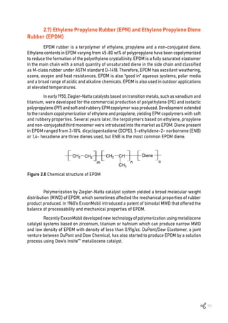
![56
Figure 2.9 Different catalyst technologies to produce EPDM rubber [29]
Some EPDM producers are still using vanadium catalyst Ziegler-Natta (ZN) catalyst
technology which gives linear polymer with low branching from cation coupling, but has
low monomer conversion and low production rate. Newer EPDM plants apply metallocene
catalysts to lower the amount of catalyst while producing EPDM with high molecular weight,
high efficiency production, narrow MWD and low gelation.
The advantages of EPDM produced by metallocene catalysis over the traditional ZN
catalysis are:
1. Higher catalyst activity resulting in the lower amounts of catalyst used.
2. Higher reaction-temperature operating window, resulting in less energy for the
deep-cooling of monomer/solvent reactor feed, the recycling of unreacted monomers and
the solvent stripping.
Commercial EPDM rubbers have average MM ranging from 10 to 600 kg/mol. Liquid
EPDMs have MM of 10 kg/mol and EPDMs extended with oil have MM up to 125 kg/mol. The
demand of EPDMs with very high molar mass extended with oil to enable both production
and mixing with maximum oil content of up to 100 phr oil is increasing as more filler
incorporation is possible.
2.7.1 Effect of molecular weight of EPDM on processability
In the molecular weight study, it was found that the average molecular weight of the
EPDM rubber dominated the compound Mooney viscosity. Low molecular weight EPDM can give
efficiency of incorporation and wetting with materials during the compound mixing process.
Bimodal EPDM provides more efficient mixing and dispersion than single broad MMD
polymers, because of the balance between shear force and wetting with materials while
compound mixing, which can reduce the mixing time.
In a branching study, it was observed that EPDM with a medium level of long chain
branching made it easier to incorporate fillers and oil into the compound matrix than the
EPDM with the higher level of long chain branching.](https://image.slidesharecdn.com/worldofrubber-2022-dr-220920074909-7d531796/85/World-Of-Rubber-58-320.jpg)
![57
2.7.2 Effect of ethylene content in EPDM on processability
In an ethylene content study, high ethylene content and highly crystalline EPDM
rubber did not soften until the compound temperature rose above its melting temperature,
resulting in the filler and oil not being easily incorporated and mixed. This affects the cycle
time of the mixing process. However, highly crystalline EPDM produces rubber product with
better physical properties than low ethylene content EPDM products. Also, the higher
crystalline EPDM compound provides the better extrusion processability.
2.7.3 EPDM and its applications
EPDM has excellent weathering, heat, oxidation and ozone resistances, as well as
excellent electrical insulation, low compression set and low temperature resistance down to
-40ºC. It can resist many polar fluids and hot water up to 200ºC. However, it is not resistant to
hydrocarbon fuels, solvents and mineral or synthetic ester lubricant and also has very poor
flame resistance. From its good properties of weathering resistance, EPDM is useful in many
seal applications, in refrigerators, window seals and automotive sealing systems (solid and
sponge seal parts), coolant hoses, grommets, transmission belts and gaskets. EPDM is also
used as an engine oil additive for insulation foam in TPV and construction industry.
Figure 2.10 EPDM application
2.7.4 How to select EPDM
Nordel™ EPDM of Dow’s are produced by Dow’s proprietary advanced molecular
catalyst (AMC) technology in solution process [30].](https://image.slidesharecdn.com/worldofrubber-2022-dr-220920074909-7d531796/85/World-Of-Rubber-59-320.jpg)
![58
NORDEL 3430 42 0.7 27 Narrow
NORDEL 3460 55 1.8 40 Medium
NORDEL 3720P 70 0.6 20 Board
NORDEL 3722P 71 0.5 18 Medium
NORDEL 3745P 70 0.5 45 Narrow
NORDEL 3760P 67 2.2 63 Medium
NORDEL 3765 XFL 67 2.5 65 Board
NORDEL 4520 50 4.9 20 Medium
NORDEL 4570 50 4.9 70 Medium
NORDEL 4571 XFM 47 4.9 70 Board
NORDEL 4640 55 4.9 40 Medium
NORDEL 4725P 70 4.9 25 Board
NORDEL 4760P 67 4.9 60 Medium
NORDEL 4770P 70 4.9 70 Medium
NORDEL 4771 XFL 71 4.9 70 Board
NORDEL 4785HM 68 4.9 85 Medium
NORDEL 4820P 85 4.9 20 Narrow
NORDEL 5565 50 7.5 65 Medium
NORDEL 6530 XFC 55 8.5 30 Board
NORDEL 6555 OE 53 8.5 55 Medium
NORDEL 6565 XFC 55 8.5 65 Board
Product Grade
Ethylene
content (%)
ENB content
(%)
Mooney viscosity
(ASTMD 1646)
MWD characteristics
(DOW test method)
Table 2.8 Product selection guide of Nordel EPDM [30]](https://image.slidesharecdn.com/worldofrubber-2022-dr-220920074909-7d531796/85/World-Of-Rubber-60-320.jpg)
![59
Table 2.9 Typical properties and applications of Nordel EPDM [30]
NORDEL™ 3430 0.86 <1 - Bale Oil and lubricant modification, peroxide-
cured parts
NORDEL™ 3640 0.86 4 -10 Bale Blends with butyl rubber in inner tubes,
peroxide-cured belts, molded goods,
conveyor belts
NORDEL™ 3720P 0.88 14 43 Pallet Thermoplastic modification, electrical
insulation, molded connectors, belts,
rolls (peroxide-cured)
NORDEL™ 3722P 0.88 15 46 Pallet Thermoplastic modification, electrical
insulation, molded connectors, belts,
rolls (peroxide-cured)
NORDEL™ 3745P 0.88 12 34 Pallet Thermoplasticmodification,cablebedding,
sound insulation, molded foam, belts
NORDEL™ 3760P 0.88 12 18 Pallet Roofing, belts
NORDEL™ 3765 XFL 0.87 12 18 Pallet Coolant hoses, belts,membranes
NORDEL™ 4520 0.86 <1 - Bale Molded seals, brake diaphragms, gaskets,
sealants, weatherstrip corner molding
NORDEL™ 4570 0.86 <1 - Bale Extrusions, automotive and general
purpose hose, profile gaskets,
weatherstripping
NORDEL™ 4571 XFM 0.86 <1 - Bale Automotive extruded profiles, coolant
hoses, building profiles, general
purpose moldings
NORDEL™ 4640 0.86 4 -10 Bale Molded automotive and industrial parts,
hose and tubing, weatherstripping, belts
NORDEL™ 4725P 0.88 12 36 Pallet Rolls, high hardness compounds, gaskets,
extruded profiles
NORDEL™ 4760P 0.88 10 35 Pallet Extrusions, automotive and general
purpose hose, profile gaskets,
weatherstripping
NORDEL™ 4770P 0.88 13 34 Pallet Automotive and general purpose hose,
extruded profiles, glass run channel,
low voltage wire and cable jacketing,
thermoplastic vulcanizates (TPV)
NORDEL™ 4771 XFL 0.87 14 34 Pallet High filler loading automotive extruded
profiles,hoses(includingradiator,industrial,
garden, and appliance), TPV, low voltage
wire and cable jacketing
NORDEL™ 4785HM 0.88 8 29 Pallet Weatherstripping,extrusions,profiles,TPV
NORDEL™ 4820P 0.91 28 79 Pallet Property modification of thermoplastic
polyolefin and thermoset rubber
formulations-high hardness, weather-
stripping, molded goods
NORDEL™ 5565 0.86 <1 - Bale Weatherstripping, extrusions, profiles,
metal carriers
NORDEL™ 6530 XFC 0.86 <1.5 - Pallet Extra fast cure molding, high hardness
rubber parts
NORDEL™ 6555 OE 0.86 <1.5 - Pallet Weatherstripping sponge profiles
NORDEL™ 6565 XFC 0.86 <1.5 - Pallet Extra fast cure, weatherstripping, dense,
micro-dense and sponge profiles
Product grade
Density
(g/cc)
Crystallinity
(mass, %)
Tg (ºC) Form Application](https://image.slidesharecdn.com/worldofrubber-2022-dr-220920074909-7d531796/85/World-Of-Rubber-61-320.jpg)
![60
2.8) Acrylic Rubber (ACM)
Acrylic rubber or polyacrylate rubber (ACM) is a copolymer or terpolymer of ethyl
acrylate and other acrylates [31], with a small amount of active cross-linking comonomers.
Polyacrylate elastomers are based on various monomers, such as ethyl acrylate (EA), butyl
acrylate (BA), methoxyethyl acrylate (MEA) and ethoxy-ethyl acrylate (EEA). These monomers
are coupled with active cross-linking comonomers, typically 2-chlorovinyl ether, vinyl
chloroacetate, allyl glycidyl ether and acrylic acid. ACM can be produced by emulsion
polymerization with radically initiated or suspension polymerization. The various copolymer
modifications can improve the properties of acrylic rubbers. The copolymer modifications
include other backbone monomers and the incorporation of reactive site groups (1-5%) for
subsequent cross-linking [2].
Figure 2.11 Chemical structure of acrylic rubber [2, 31]
Because ACM is a saturated rubber, it is impossible for it to be vulcanized through
traditional sulphur vulcanizing systems like unsaturated rubbers. However, acrylic rubbers
can be cross-linked by diamines, fatty acid soaps and peroxides. The selections of the
cure-site monomers and the corresponding curing agents are a critical aspects in the
influencing the characteristics of the acrylic rubbers [31]. Monomers containing active
cure-sites (i.e., epoxy, chlorine, and carboxyl groups) have traditionally been the most favored
for industrial applications. These with carboxylic and epoxy cure-sites are relatively safe, but
chlorinated monomers cause serious problems of toxicity and corrosion issues [31].
The self-contained reactive sites are not activated until the high temperature of
vulcanization, 170ºC or higher. In self-cross-linked elastomers the scorch and vulcanizing
rate can be accelerated by the addition of an acidic material such as phthalic anhydride during
the compounding.](https://image.slidesharecdn.com/worldofrubber-2022-dr-220920074909-7d531796/85/World-Of-Rubber-62-320.jpg)
![61
Cure-site monomers Curing system
Halogen groups - Soap-sulphur or peroxide
- Trithiocyanuric acid and calcium hydroxide
- Aliphatic polyamines
Carboxyl groups - Quaternary ammonium salts
- Hexamethylenediamine carbamate and
N,N’-diortholylguanidine coagent
Epoxide groups - Quaternary ammonium salts
- An isocyanuric and quaternary ammonium salts
- UV
Unsaturated double bonds - Sulphur and peroxide
Carboxyl groups - Quaternary ammonium salts
Chlorine groups - Hexamethylenediamine carbamate
- Non-alkali metal oxy compound and quaternary
ammonium salts, tertiary amine or guanidine
- A combination of Sodium stearate and
tetramethylthiuram disulphide
Carboxyl and epoxide groups - Quaternary ammonium salts
- Guanidine compound and diamine compound
Aliphatic diamine carboxylate Polyvalent amine
Table 2.10 Species of cure-site monomers and their corresponding curing systems of
acrylate rubbers
2.8.1 Characteristics of acrylic rubber
The combination of a saturated backbone and polar side chain make acrylic rubber
outstanding in resistance to high heat aging, environmental oxidation and hydraulic and
mineral oils. Acrylic rubber also good resistance with ozone and weathering resistance than
nitrile rubber. On the other hand, acrylic rubber has poor resistance to acids, alkalis, water
and moisture. Although acrylic rubber can resist high temperature, but for low temperature
applications are usually limited to approximately -14°C [31]. it will lose the flexibility and
compression set. Ethylene acrylate rubber (AEM) is known under the trade name “VAMAC”
from DuPont has characteristics like ACM, however a better rigidity, heat resistance, but
worse mineral oil resistance.
2.8.2 Ethylene acrylic elastomers (AEM)
Ethylene acrylate copolymers are synthetic elastomers composed of ethylene and
methyl acrylate. The ethylene repeating units are outstanding in good low temperature
properties, and the acrylic component helps to improve swelling resistance in non-polar oils.
Due to the saturated backbone with polar side groups like ACM, AEM is also better than ACM
in resistance to heat, ozone, weathering and many chemicals [32]. AEM is also outstanding
in vibration damping and abrasion in a wide range of temperature.](https://image.slidesharecdn.com/worldofrubber-2022-dr-220920074909-7d531796/85/World-Of-Rubber-63-320.jpg)
![62
Figure 2.12 Chemical structure of ethylene acrylate copolymer (AEM) [31]
AEM rubber is mostly use in the application that required ozone, heat and some
mineral oils at moderate temperatures below 150ºC [31, 33]. However, AEM rubbers should
not be exposed to aromatic hydrocarbons, gasoline, brake fluids and phosphate esters.
2.8.3 Applications of acrylic rubber (ACM/AEM)
Acrylic rubbers are commonly used in automotive transmission, power steering
seals and O-rings that have to be resistant to transmission fluids and many other common
automotive lubricants and hydraulic fluids. Other applications are diaphragms, plumbing
seals, boots, hoses, vibration mounts, pads, isolators and custom molded rubber goods and
parts. Previously, almost all applications required a service temperature range from -30ºC
to 150ºC. Furthermore, some have the potential to reach 175ºC for a short period of time.
Grade
ML 1+4
(100ºC)
Key feature
Tg by DSC
(ºC)
Vamac® G 16.5 -30 General purpose
Vamac® GXF 17.5 -30 Dynamic fatigue resistance
Vamac® GLS 18.5 -23 Low oil swell
Vamac® HVG 26.0 -30 High viscosity
Vamac® Ultra XF 23.0 -30 Intermediate viscosity
Vamac® Ultra IP 29.0 -30 Improved performance grade for
molding & extrusion
Vamac® Ultra HT 29.0 -30 High temperature
Vamac® Ultra HT-OR 31.0 -24 High temperature / Oil resistance
Vamac® Ultra LS 33.0 -23 High viscosity / Low oil swell
Vamac® Ultra DP 22.0 -27 Peroxide curable dipolymer
Vamac® Ultra DX 28.0 -29 Improved processing peroxide
curable dipolymer
VMX4017 11.0 -41 Low temperature
Table 2.11 DuPont Vamac® grade [34]](https://image.slidesharecdn.com/worldofrubber-2022-dr-220920074909-7d531796/85/World-Of-Rubber-64-320.jpg)
![63
Table 2.12 DuPont Vamac® grade [34]
1 Tg of compounds with Vamac® may be extended typically -10ºC lower with addition of plasticizer
2 Not suitable for steam autoclave cure.
Grade ML 1+4
(100ºC)
Key feature
Tg by DSC (ºC)1
VMX5015 67.0 -23 Compression molding pre-compound2
VMX5020 53.0 -30 Injection molding pre-compound2](https://image.slidesharecdn.com/worldofrubber-2022-dr-220920074909-7d531796/85/World-Of-Rubber-65-320.jpg)
![64
2.9) Silicone Rubber
Silicone rubber is an elastomer composed of silicon and oxygen atoms that covalently
bonded in a molecular chain of inorganic siloxane (Figure 2.13) [35, 36]. It is resistance to ozone,
UV, heat and chemicals which is very stable in extreme environments. It also has excellent
dielectric strength (at high voltage) fire resistance and good mechanical properties at extreme
temperatures [36, 37]. Therefore, it is a material selected by food, medical, electric and wire
and cable industries which require good chemical and environmental resistant material and
can retain the initial shape and mechanical strength under heavy thermal stress or sub-zero
temperatures. It also finds its useful applications in high voltage line insulators; automotive
wire harness applications; electronics; sealants for aviation applications. However, silicone
rubber has low tensile strength, poor wear and tear wear properties [36, 38, 39].
Figure 2.13 Chemical structure of silicone rubber [35]
2.9.1 Structure
Polysiloxanes structure in silicone rubber differs from other hydrocarbon polymers
that in the back bones consist of Si-O-Si unites. Because of the bond energy of Si-O is much
higher than C-C bond of hydrocarbon rubber [38], therefore, silicone rubber is more stable
to environment and UV than the hydrocarbon rubbers. Polysiloxane is very flexible due to the
large bond angles and bond length when compared to C-C back bone of other hydrocarbon
polymers. Polymer segment of silicone rubber can move farther and change conformation
easily. Polysiloxanes is stable and less chemical active and it is more stable than hydrocarbon
rubber because of higher charge and mass of silicone with 14 protons and 14 neutrons and
add layer of electrons which has screening effect changes the electronegativity (Carbon atom
of hydrocarbon rubber has only 6 protons and 6 neutrons).
2.9.2 History of silicone rubber
Swedish chemist, Jons Jackob Berzelius heated silicon in his laboratory with chlorine,
after a vigorous blast, he found silicon tetrachloride which was one of raw material used
to produce silicone today. Not further development was carried on significantly until the
beginning of 1930 Dr. J. Franklin Hyde, a chemist at Dow Corning Corporation in Midland who
worked on corning glass works, researched on element silicone research and developed
into silicones. His work had been developed by Dr. Frederick Stanley Kipping who achieved
the synthesis of silicone compounds [40].
One of the first uses of silicones was in toys. Silicone rubber is a very soft material
that has viscoelastic properties that could bounce. In 1969, Neil Armstrong took his first step](https://image.slidesharecdn.com/worldofrubber-2022-dr-220920074909-7d531796/85/World-Of-Rubber-66-320.jpg)
![65
on the moon. Rubber outsoles of his boots were made of silicone. Nowadays, silicones are
widely used in automotive, aerospace, electrical industry and medical devices and molding [36].
2.9.3 Curing
The un-vulcanized silicone rubber must be cured, vulcanized or catalyzed in order
to cross-link the polymer chains. This is normally used in a two-stage processes at the point
of manufacturing into the desired product. Any one of the following curing systems is used
to cure the un-vulcanized material.
‹Peroxide cure system
Peroxide curing is normally used for curing silicone rubber [38]. The curing process
leaves behind by-products which usually need a post-curing process to reduce the peroxide
breakdown products. Dicumyl peroxide is commonly used.
‹Addition cure system
This curing system is also known as the platinum-based cross-linking system.
In this curing system, a hybrid- and a vinyl-functional siloxane polymer reacts with a
platinum complex catalyst, forming an ethyl bridge between the functional groups. There
is no by-product of the reaction. The reaction occurs quickly, but if sulphur element or any
amine compounds are present, the rate of curing is prevented [37].
‹Condensation cure system
Condensation curing systems can be one-part or two-part system [37]. In one-part
or room-temperature vulcanizing (RTV) system. The crosslinker exposed to the ambient
humidity cased a hydrolysis step. The silanol condenses further with another hydrolysable
group on the polymer or crosslinker and reactions continue until the system is fully cured.
In contrast to the platinum-based addition cure system, such a curing system will cure at
room temperature and is not easily countered by contact with other ingredients. Two-part
condensation system package, the crosslinker and condensation catalyst are in the first
part while the polymer and other ingredients (i.e., filler and pigment) are in the second part.
The curing process is started by combining two parts. Typically, sealants, thermal insulation
ablative material and aerospace materials are among the applications for this type of curing
system [38].
2.9.4 Classified of silicone rubber
Silicone rubber is classified into four groups by polymer type and performance
characteristic, as shown below [41].
Polydimethyl siloxane elastomer (MQ) contains only methyl groups on the
molecular chains [41].](https://image.slidesharecdn.com/worldofrubber-2022-dr-220920074909-7d531796/85/World-Of-Rubber-67-320.jpg)
![66
Figure 2.14 Chemical structure of molydimethyl siloxane elastomer [41]
Vinyl methyl siloxane (VMQ) is similar to polydimethylsiloxane (MQ), but it has
methyl and vinyl groups which known as methyl vinyl silicone rubber [41].
Figure 2.15 Chemical structure of vinyl methyl siloxane elastomer [41]
Polymethyl/vinyl/phenol siloxane elastomers (PVMQ) contains methyl, phenyl and
vinyl groups on the polymer chains [41]. It is excellent in low temperature performance [42].
Figure 2.16 Chemical structure of polymethyl/vinyl/phenol siloxane elastomer [41]
Poly-Ƴ-trifluoropropyl methyl/ vinyl methyl siloxane elastomer (FVMQ) contains
fluoro, vinyl and methyl groups on the molecular chains [41]. This silicone rubber is extremely
resistant to oil, chemicals and other fluids, with improved heat resistance [41].
Figure 2.17 Chemical structure of poly-Ƴ-trifluoropropyl methyl/ vinyl methyl siloxane
elastomer [41]](https://image.slidesharecdn.com/worldofrubber-2022-dr-220920074909-7d531796/85/World-Of-Rubber-68-320.jpg)
![67
2.9.5 Silicone material classification
Silicone material rubber can be classified into three forms including, solid silicone
rubber (HCR), liquid silicone rubber (LCR) and room temperature vulcanized (RTV)
‹Solid silicone rubber (HCR)
Solid silicone rubber (HCR) or high-temperature vulcanized (HTV) is a silicone rubber
with high molecular weight and long chain. They are un-vulcanized rubber or raw rubber
[38]. This silicone is suitable for compounding and molding processes. Because of the high
viscosity of silicone rubber, it may be mixed and process in the same way as other rubber
such as NR, EPDM and others elastomers. They are cure by peroxide or platinum catalyst
and require post-cure to ventilate organic peroxide by-products in order to maximize and
stabilize rubber properties. It can enhance physical properties of silicone rubber while also
reducing the odor of small organic or acidic materials.
‹Liquid silicone rubber (LSR)
Liquid silicone rubber (LSR) has a lower molecular weight and shorter chains length
than HTV. Because of its low molecular weight, it has superior flow properties and is suitable
for specially low injection pressure and low pressure extrusion processes [36]. This material
increase productivity by reducing cycle time, minimizing material waste and allowing for
the use of smaller machines [43]. The vulcanization of LSR is exclusively carried out with a
platinum-catalyzed hydrosilylation.
‹Room temperature vulcanized (RTV)
Room temperature vulcanized (RTV) is a kind of silicone rubber produced from
one-part or two-component systems; condensation cross-linked materials and addition
cross-linked polymers [36]. RTV is designed to be cured in a room temperature environment.
RTV is also widely used for a wide range of applications because to its ability to flow to soft
pastes, good thermal resistance, great adhesion and particularly curing without heating
temperature [39]. As a results, it is useful for sealants, adhesives and protective coating with
metal, plastic and wood for both indoor and outdoor [39].
2.9.6 Peroxide vulcanization of silicone rubbers
It is not all kinds of organic peroxide are suitable for curing silicone rubbers.
The dialkyl peroxides such as dicumyl peroxide can cure silicone rubbers, which contain
vinyl groups (VMQ). Saturated silicone rubbers (MQ) require diacyl peroxides such as
bis-(2,4-dichlorobenzoyl) peroxide to be curing agent. In peroxide vulcanization, it can be
divided in to two steps of vulcanization. First step occurs in molding process vary from about
100ºC to 180ºC, called preliminary vulcanization. The second step occurs at the post cure stage
with high temperature around 180ºC in the ventilation oven. In this high temperature post cured
stage, the acidic materials that came out behaved as a catalyze hydrolytic decomposition of
the vulcanizate and form an additional cross-linked product [44].](https://image.slidesharecdn.com/worldofrubber-2022-dr-220920074909-7d531796/85/World-Of-Rubber-69-320.jpg)
![68
Figure 2.18 Peroxide vulcanization for silicone rubber [37]
2.9.7 Additives and fillers for silicone rubber
In order to enhance its properties, silicone rubbers are normally produced in rubber
compounds by adding various additives such as filler, flame retardant and pigment.
Reinforcing fillers such as silica and carbon black are used as reinforcing fillers in
silicone compounding to improve mechanical and conductivity properties of silicone products
[45, 46].
Heat stabilizer is mainly applied in silicone rubber to improve thermal resistance
and also enhance mechanical properties for silicone rubber [47].
Flameretardantisusedinlowcontenttoimproveflameresistanceofendproduct[48].
Pigment such as titanium dioxide and other organometallic compounds as
pigments can be added into silicone rubber that give transparency for silicone products even
needed in some application. For titanium dioxide, it forms aggregates easily and probably is
aggregated in the silicone rubber in view of the high loadings that are possible [49].
2.9.8 Silicone rubber applications
Silicone rubber has been considered safe in the United States and Canada for
applications in consumer cookware and medical products since the FDA approved it in 1979.
However, the European Union has labelled chemicals D4, D5, and D6, used in the production
of silicone rubbers, due to, they concern that some of chemicals can leach from silicone
products. The majority of silicone rubber are beneficial in industry, both on their own and
when combine with other elastomers or materials.
Silicone rubber is frequently used in applications for insulating tape, sealant,
varnish, lubricants, keyboards, and housings due to its high purify or low toxicity.
Silicone rubber is widely applied in seals, tooling materials, spacesuit fabrics and
gaskets for aerospace and aircraft parts, due to its wide temperature service range (-100ºC
to 300ºC),
Silicone rubber is used in construction as adhesive, sealant, and coating due to
its weathering resistance properties and ability to bond to metal.
Silicone rubber can be used for heat, oil, and fuel resistance in automotive
applications in addition to using coatings and varnishes.
Silicone rubber can be used in medical parts as tubing, adhesives, and defoamers.
Food containers, utensils, toys, and even silicone rubber band bracelets may be
produced from silicone rubber.](https://image.slidesharecdn.com/worldofrubber-2022-dr-220920074909-7d531796/85/World-Of-Rubber-70-320.jpg)
![69
2.10) Fluoroelastomers (FKM)
Fluoroelastomers (FKM) are remarkable elastomers that are used in harsh
environments and when other elastomers would fail to resist heat and chemicals [50].
The original FKM were developed by the Du Pont company in 1957 [51]. Nowadays, FKM
are produced by many companies, including Daikin (DAI-El), 3M (Dyneon), Solvey S.A.
(TECHNOFLON) and some local manufacturers also exist in China and Russia [50, 51]. There
are presently several applications for fluoroelastomers due to their crucial role in resolving
critical issues in the aerospace, automotive, chemical and petroleum industries [51]. Other key
benefits include excellent resistance to aging and ozone, very low gas permeability and being
self-extinguishing material [52]. Additionally, the fluorine content has an impact on a variety
of properties of fluoroelastomers, including fluid resistance and low temperature properties.
2.10.1 Types of FKMs
Based on the monomer composition, fluorocarbon elastomers are classified in ASTM
D 1418 as follows [53-55]:
Type 1: The copolymer of FKM is comprised of vinylidene fluoride (VDF) and
hexafluoropropylene (HFP), which is a popular kind of fluoroelastomer [54]. These copolymers
are cured by bisphenol to give a strong overall performance and are used in general-purpose
applications [54]. They contain around 66 percent fluorine by weight.
Type 2: These terpolymers of FKM composed of VDF, HFP and tetrafluoroethylene
(TFE) have a higher fluorine content than other copolymers (typically between 68-69.5% weight
percent fluorine). This improves heat resistance, and chemical resistance. On the other hand,
it may have a negative impact on compression set and low temperature [55].
Type 3: A ternary copolymer containing, VDF, TFE and perfluoromethyl vinyl ether
(PMVE) is one type of FKM that offers better low temperature flexibility. Fluorine content in
type 3 FKM varies from 62-68 %wt [53, 56].
Type 4: The other kind of FKM terpolymer is made of VDF, propylene, and TFE. It
contains fluorine approximately 67 weight percent content. In comparison to FKM, this kind
of other FKM has improved low temperature performance, better electrical properties and
steam resistance.
Type 5: This kind of FKM, composed of VDF, HFP, TFE, PMVE and ethylene, especially
provides better low-temperature performance, low swelling in hydrocarbon and greater
chemical resistance (i.e., base).
2.10.2 Chemical structures
If FKMs are generated from hexafluoropropylene (HFP) and vinylidene fluoride (VF2),
the polymers are referred to as dipolymer. Approximately 66%wt of fluorine is found in the
dipolymer [57]](https://image.slidesharecdn.com/worldofrubber-2022-dr-220920074909-7d531796/85/World-Of-Rubber-71-320.jpg)
![70
Figure 2.19 Vinylidene fluoride-co-hexafluoropropylene [58]
Figure 2.20 Tetrafluoroethylene-hexafluoropropylene-vinylidene fluoride [58]
Figure 2.21 Vinylidene fluoride-tetrafluoroethylene-perfluoroalkyl vinyl ether [58]
If FKMs come from VF2, HFP and tetrafluoro-ethylene (TFE), the polymers are called
terpolymers and will contain 68%wt fluorine content [57].
Scientists developed a terpolymer consisting of VF2, HFP and perfluoroalkyl vinyl
ether (PTFE) to enhance the performance of FKM at low temperarture. The fluorine content
is 64%-67% providing good low temperature flexibility [54].
DuPont Dow Elastomers L.L.C produces Viton as advanced polymer architectures
(APAs) that have much better performance in low temperature and chemical resistance. This
APA polymer is used in oil and gas applications [59].
Figure 2.22 Fluorene content on solvent and low temperature resistance [55]](https://image.slidesharecdn.com/worldofrubber-2022-dr-220920074909-7d531796/85/World-Of-Rubber-72-320.jpg)
![71
The performance of FKM rubber is affected by fluorine content, as shown in Figure 2.22.
It can be seen that with increasing fluorine content, the low temperature resistance (ºC)
tested using TR-10 method increased, and the volume swell in methanol for 40 hrs at 70ºC
decreased [55].
2.10.3 Curing of FKMs
Amine/Diamine curing has been used for curing FKM since 1950. In the late of 1960,
the bisphenol curing system was introduced. Bisphenol curing with accelerators can
accelerate the cure rate of FKM. Phosphonium salt, hexamethylenediamine carbamate and
N,N’-dicinnamylidene-1,6 hexanediamine are normally used as accelerators. Although diamine
cure outperforms bisphenol cure in terms of heat aging and compression set, the bisphenol
cured system outperforms diamine cure in terms of metal adhesion and faster curing rate [60].
Since 1950, peroxide with triallyl isocyanurate systems has been used in FKM
cross-linked systems. Peroxide cure can improve physical properties, heat aging resistance
and chemicals resistance. Additionally, peroxide-cured fluoroelastomers provide greater
resistance to steam, acids, and other aqueous solvents while not requiring metal oxide
activators as used in bisphenol cure systems [56, 60].
In cross-linking FKM, metal oxides such as Ca(OH)2, CaO, MgO, ZnO, and PbO are
necessary to absorb traces of HF generated during the curing process [60].
2.10.4 Post Cure
For most rubbers peroxide cured, “post-cure” is necessary to achieve their optimal
physical product properties. The post-cure is performed in an air-circulating oven for 2 to 24
hrs at 150-250°C, depending on the size and thickness of products [61]. Post-cure is a step
to eliminate residual volatiles from inside the vulcanizates. Post curing will improve various
properties such as tensile strength, and compression set but may provide low elongation at
break. Post-cure is most critical for bisphenol and peroxide cures of FKMs to achieve the
optimal properties.
From figures 2.23(a) and 2.23(b), temperatures of post cure affect to compression
set of moulded parts. It can be seen that Viton showed performance improvement of products
post cured at temperatures 200ºC and 232ºC with the time of post curing. Higher post cure
temperature and longer post cure time improve compression set [61].](https://image.slidesharecdn.com/worldofrubber-2022-dr-220920074909-7d531796/85/World-Of-Rubber-73-320.jpg)
![72
Figure 2.23 Compression set of bisphenol AF-cured and peroxide-cured formulations after
post-curing at 200ºC (a) and 232ºC (b) for a period of 4-24 hrs [61]
Figure 2.24 Tensile strength of bisphenol AF-cured and peroxide-cured formulations after
post-curing at 200°C (392°F) for a period of 4-24 hrs [61]](https://image.slidesharecdn.com/worldofrubber-2022-dr-220920074909-7d531796/85/World-Of-Rubber-74-320.jpg)
![73
Tensile strengths of bisphenol AF-cured and peroxide-cured formulations after
post-cure at 200ºC are shown in Figure 2.24. It can be seen that tensile strength of products
enhanced after post-curing. All products show higher %improvement in biphenyl cured than
peroxide cured at higher temperature and longer post cured time [61].
2.10.5 Application of FKMs
In automotive industry: Because of fuel resistance, low fluid leaks and high and
low temperature resistance, FKMs have been used for many automotive parts for fuel and
combustion systems such as fuel hose, seal, gasket and O-ring of the engine.
In chemical plants; FKMs have been used for gaskets and seals because of high
resistance to petrochemicals, steam, acids, and bases.
In oil & gas drilling processes; fluids contain petroleum and chemicals so, FKMs
have been selected for rubber products in the oil and gas industry.
In aerospace; Polymers that are used in aerospace must have high and low
temperature flex resistance, FKMs and perfluoroelastomers are the choice.
2.10.6 Product reference from DuPont
Viton® fluoroelastomers are classified as A, B, or F based on their fluid and chemical
resistance. Fluid resistance varies with fluorine content in the polymer, which is decided by
the types and relative contents of copolymerized monomers that compose the polymer [62].
Viton A is a dipolymer made from vinylidene fluoride (VF2) and hexafluoropropylene
(HFP). It is commonly used in injection molding, extrusion and solution coating. Furthermore,
this kind of FKM is used for a variety of applications such as O-rings, roll covers, gaskets,
fuel hose and tubing, parts with complicated shapes and solution for coatings of tanks and
fabrics [62-64].
VitonBisaterpolymerpolymerizedfromvinylidenefluoride(VF2),hexafluoropropylene
(HFP), and tetrafluoroethylene (TFE) monomers and does not contain a curing agent. This
kind of FKM needs to be cross-linked or cured by a diamine or bisphenol cured system to
obtain the final rubber vulcanizate. The higher fluorine content of Viton gives it better fluid
resistance than Viton A [62].
Viton F is also a terpolymer that is polymerized from vinyl fluoride (VF2),
hexafluoropropylene (HFP), and tetrafluoroethylene (TFE) like Viton B, but gives the best fluid
resistance of all the Viton types. So, Viton F is usually used for applications that require low
fluid permeation [62].
Viton GB and Viton GBL are terpolymers that are polymerized from vinyl fluoride
(VF2), hexafluoropropylene (HFP), and tetrafluoroethylene (TFE). They are designed to use
peroxide cure to provide higher resistance to aggressive automotive lubricating oils, steam
and acids [62].
Viton GLT is a terpolymer that is designed to resist chemicals and high temperature
while improving low temperature flexibility. GLT has a temperature resistance range 8ºC to
12ºC lower than that of general Viton grades [62].
Viton GFLT is similar to Viton GLT in that it is reported to increase the low
temperature performance of Viton GF, can resist high temperature and is also resistant to
a variety of chemicals [62].](https://image.slidesharecdn.com/worldofrubber-2022-dr-220920074909-7d531796/85/World-Of-Rubber-75-320.jpg)
![74
Table 2.13 Polymer fluorine content versus fluid resistance and low temperature flexibility [65]
*Nominal values, based on results typical of those obtained from testing a standard, 30 phr MT (N990) carbon black filled, 75 durometer vulcanizate. These are
not intended to serve as specification.
Properties
Standard types
A B F GLT-S GFLT-S ETP-S
Nominal polymer fluorine content, %wt
Percent volume change in Fuel C,
168 hrs at 23ºC (73ºF)*
Percent volume change in methanol,
168 hrs at 23ºC (73ºF)*
Percent volume change in methyl ethyl
ketone, 168 hrs at 23ºC (73ºF)*
Percent volume change in potassium
hydroxide, 168 hrs at 23ºC (73ºF)*
Low temperature flexibility, TR-10, ºC*
66 68 70 64 67 67
4 3 2 5 2 4
90 50 5 90 5 5
>200 >200 >200 >200 >200 19
(Sample too swollen and degraded to test) 14
-17 -13 -6 -30 -24 -12
Table 2.14 Comparison of cure systems used in cross-linking Viton™ [65]
Property, processing characteristic
Type of cure system
Diamine Bisphenol Peroxide
Processing safety (scorch) P-F E E
Fast cure rate P-F E E
Mold release/ Mold fouling P G-E G-E
Adhesion to metal inserts E G
G
Compression set resistance P E E
Steam, water, acid resistance F G E
Flex fatigue resistance G G G
Rate, E= excellent, G=Good, F=Fair, P=Poor
Table 2.15 Physical property differences among types/families of Viton products [65]
1=Excellent-Best performance capability of all types, 2= Very Good, 3= Good-Sufficient for all typical fluoroelastomer applications
*See Table 4 for a detailed guide to choosing the best type of Viton™ fluoroelastomer relative to specific classes of fluids and chemicals.
**Flexibility, as measured by temperature of retraction (TR-10), Gehman torsional modulus, glass temperature transition (Tg), or Clash-Berg temperature,
brittle-point tests are a measure of impact resistance only and do not correlate at all with the low temperature sealing capability of a vulcanizate.
Type of Viton
Fluoroelastomer
Resistance to
compression set*
General Fluids/
Chemical resistance*
Low temperature
flexibility**
A 1 3 3
B, GBL-S 2 3 3
F, GF-S 3 2 3
GLT-S 2 3 1
GFLT-S 2 2 2
ETP-S 3 1 3](https://image.slidesharecdn.com/worldofrubber-2022-dr-220920074909-7d531796/85/World-Of-Rubber-76-320.jpg)
![75
Table 2.16 Differences in fluid resistance among types of Viton Fluoroelastomer [65]
l volume increase, change in physical properties.
2= Very Good-Good serviceability in this class of fluid/chemical, small amounts of volume increase and/or changes in physical properties.
3=Good-Suitable for use in this class of fluid/chemical, acceptable amounts of volume increase and/or changes in physical properties.
NR= Not recommended-Excessive volume increase or change in physical properties
Hydrocarbon automotive,
aviation fuels
Oxygenated automotive fuels
(containing MeOH, EtOH, MTBE,
etc.)
Reciprocating engine lubricating
oils (SE-SF grades)
Reciprocating engine lubricating
oils (SG-SH grades)
Aliphatic hydrocarbon process
fluids, chemicals
Aromatic hydrocarbon process
fluids, chemicals
Aqueous fluid: water, steam,
mineral acid (H2SO4, HNO3,
HCl, etc.)
Amines, high pH caustics (KOH,
NaOH, etc.)
Low molecular weight carbonyls
(MTBE, MEK, MINK, etc.)
1 1 1 1 1 1 1 1 1
NR 2 1 NR 2 1 NR 1 1
2 1 1 1 1 1 1 1 1
3 2 2 1 1 1 1 1 1
1 1 1 1 1 2 1 1
2 2 1 1 1 1 2 1 1
3 2 2 1 1 1 1 1 1
NR NR NR 3 3 3 3 3 1
NR NR NR NR NR NR NR NR 1
Type of Viton
Cure system
A B F
Bisphenol Peroxide
GAL-S GBL-S GF-S GLT-S GFLT-S ETP-S
2.10.7 Processing of fluoroelastomers
The essential principle for compounding fluoroelastomer is the same as for other
elastomers. The grade of fluoroelastomer and other ingredients used are decided by the
required properties of the final vulcanizate (or finished product) as well as by the rubber
compound’s behaviour during rubber processing (i.e., mixing and curing). On the other hand,
the slow relaxation rates of fluoroelastomers presents an issue for rubber processing steps
including, mixing, extrusion, and injection processes which are generally run at high shear
rates [54]. Furthermore, fluoroelastomer compounds cause issues during rubber processing
such as sticking to mold surfaces, and of inadequate adhesion to metal inserts [54]. The
relatively low production volume of fluoroelastomer parts production requires that equipment
used for other high-volume elastomers be adapted to fluoroelastomer processing [54].
‹ Mixing
It has previously been noted that fluoroelastomer compounding is normally performed
in small batch size mixing equipment because of high materials costs and limited production
quantities. However, most mixing has been transferred from two roll mills to internal mixer as
volume has increased and quality control has become more critical [54]. In general,](https://image.slidesharecdn.com/worldofrubber-2022-dr-220920074909-7d531796/85/World-Of-Rubber-77-320.jpg)
![76
fluoroelastomers should be mixed on as cool as possible two roll mill (i.e., at 23ºC) [66]. Avoiding
contamination of fluoroelastomer compounds is a critical issue for a rubber production unit
that also handles other elastomers. Strict cleaning processes are necessary to ensure that
elastomer, oil, grease, and other contaminants are removed from equipment before and after
processing fluoroelastomers.
‹ Compounding ingredients
Ingredients for compounding should be stored in sealed containers stored in cool,
dry conditions. Metal oxides and hydroxides that may interact with moisture and carbon
dioxide in ambient air should be kept carefully. Excessive moisture uptake by elastomer, filler,
or other ingredients can lead to unpredictable curing and defects in fabricated parts such
as porosity [54]. Some ingredients must be used in special forms to provide good dispersion
and curing performance [54]. Curative uniform dispersion is especially challenging in rubber
compounds cured with the bisphenol system.
Bisphenol AF crosslinker and quaternary phosphonium salt accelerators are
high-melting solids that must be micropulverized to fine particles for good dispersion in
rubber compounds [51, 54]. Because many fabricators would have problems in attaining the
uniform dispersion necessary for reproducible curing, polymer producers offer these
curatives pre-mixed with fluoroelastomer in the form of pre-compounded grade, which
gives the optimal combination of curative agents (i.e., accelerator and curing agents) [51].
For example, DuPont Dow supplies the VDF/HFP dipolymer Viton® E-60 as a gum polymer
to be mixed with curing agent as well as Viton® E-60C as a pre-compound. Bisphenol AF
(BPAF) and benzyl triphenyl phosphonium chloride (BTPPC) in the proper amounts are
offered for optimized cure characteristic [54]. The concentration of curative VC-30, 50% BPAF
in dipolymer, and VC-20, 33% BTPPC, are readily incorporated by fabricators in the amounts
chosen for the optimized cure characteristic [54]. Similar curative concentrates are offered
by other fluoroelastomer suppliers. DuPont Dow and Dyneon also offer pre-compounds that
contain curative in the form of a mixture of BTPP+ BPAF- salt with additional BPAF (weight
ratio BPAF/BTPP+ about four) [54]. The isolated mixture which is supplied by DuPont Dow
as VC-50 is a low-melting glass that is readily dispersed. As is well known, providers of
fluoroelastomer offer a variety of bisphenol curable in a pre-compound form, typically with
processing aids, for different purposes. With the guidance of these materials, manufacturers
may be sure that the compounding will process the desired cure characteristics and produce
a vulcanizate with the finest potential properties [54].](https://image.slidesharecdn.com/worldofrubber-2022-dr-220920074909-7d531796/85/World-Of-Rubber-78-320.jpg)
![77
2.11) Thermoplastic Vulcanizate (TPV)
Thermoplastic vulcanizate (TPV) is a kind of thermoplastic elastomer (TPE) which
combines the characteristic of elastomeric behaviour and thermoplastic processability. It can
be melt-processed and reshaped by using conventional thermoplastic processing equipment
such as injection, extrusion and compression machines. Unlike the others in the TPE family, TPV
consistsofmicro-sizevulcanizedrubberparticlesencapsulatedinthermoplasticmatrix[67].That
results in the TPV having elastomeric properties and appearance of traditional thermoset rubber.
Ingredients of TPV are usually EPDM and PP. However, engineering TPVs of acrylic rubber and
polyester resin have been developed to serve the requirements of high temperature and oil
resistant applications. NR-TPV has also been developed to serve the purpose of green resin.
TPV is normally produced by a reactive mixing process namely “Dynamic Vulcanization
(DV)”. High porting of raw rubber is melt-mixed with thermoplastic under high shear condition
and temperature in the presence of cross-linking agent. At the initial stage of mixing, both rubber
and plastic phase are elongated in the flow field and preferably form a co-continuous phase.
When the cross-linking reaction is activated, the viscosity of the rubber phase increased.
The changes in rubber-plastic viscosity ratio and interfacial tension cause phase inversion.
Finally, fully cured rubber is presented as a disperse phase in the thermoplastic matrix. On an
industrial scale, dynamic vulcanization is done by a twin screw extruder as shown in Figure 2.25.
That promotes high productivity, good temperature control and provides high shear rate and
stress for breaking the cured elastomer phase. Twin screw extruders for TPV have been
developed and patented for many years in various aspects such as screw configuration, L/D
ratio, screw element as well as processing parameters and control system.
Figure 2.25 Schematic process of TPV production by twin-screw extruder](https://image.slidesharecdn.com/worldofrubber-2022-dr-220920074909-7d531796/85/World-Of-Rubber-79-320.jpg)
![78
In principle, cross-linking reaction of the elastomer phase could be achieved by adding
several chemical reagents. Sulphur is the preferable curing agent in the rubber industry but it
is not applied in commercial TPV because the weak S-S linkage leads to low thermal stability
of TPV during processing and low weathering resistance of the finished product. Nowadays,
the preferred curing systems are peroxide and resole-phenolic resin systems [68].
Peroxide cross-linked systems provide good elastic behaviour in particular
compression set, and high temperature resistance caused by the strong C-C linkage. Moreover,
there is no discoloration of the final products. The suitable peroxide should be selected on the
basis of its decomposition rate at the processing temperature. Other criteria for the selection
of the peroxide relate to the compatibility with polymer base and propensity to decompose
into smelly by-products. Coagents are popularly added in peroxide cross-linked systems.
Coagents are multifunctional monomers that are highly reactive toward free radicals
to enhance properties of vulcanizates. Coagents increase cure rate and state of cure,
consequently, thermal resistance and mechanical properties of TPV are improved. However,
the peroxide systems in TPV production have low selectivity. In some cases, free radicals
generated from peroxide decomposition lead to the abstraction of hydrogen atoms from
the polymer chain and result in polymer radicals which can combine to form C-C linkages.
Sometimes, H-abstraction occurs on the thermoplastic main chain (i.e., polypropylene) causing
undesired side reactions such as β-chain scission and the breakdown of polypropylene.
Resole-phenolic resins, the poly condensation products of phenols and aldehydes,
are called “workhorse” for TPV. Resole-phenolic resin generally consists of reactive
methyl-groups and dimethylene-ether units that can react with the unsaturated elastomer
phase selectively at the processing temperatures and yields thermally-stable cross-links.
The cross-linking mechanism of elastomer by resole-phenolic resin has been widely reported.
During the cross-linking reaction, ether linkages are split by SnCl2 as an activator (other
halogen containing reagents can also be used), providing mono-phenolic units having benzylic
cations. After that, cationic intermediates add to the unsaturated bond and cross-linking
elastomer chains occur. In the case of the absence of the unsaturated bond in thermoplastic,
resole-phenolic does not react with thermoplastic. That is one of the benefits of the phenolic
curing system over the peroxide system by avoiding the degradation of the thermoplastic
segment by the chain scission reaction. That results in excellent properties and good
processability of the corresponding TPV.
TPV can be made from various rubber-plastic pairs depending on their compatibility
and required specific property of final product. However, Ethylene-propylene-diene monomer
rubber (EPDM) and polypropylene (PP) based TPV, are the popular ones in the TPV market
today. EPDM/PP based TPV was intensively studied in the 1980s and was commercially
introduced by Monsanto in 1981. Saturated main chains in EPDM rubber, as well as high
crystallinity and melting point of PP offer good resistance to heat, oil, oxygen, and ozone. So,
it can be used in various applications, especially in the automotive industries, because of its
excellent weathering resistance, low density, and relatively low manufacturing cost compared
to cross-linked rubber parts.](https://image.slidesharecdn.com/worldofrubber-2022-dr-220920074909-7d531796/85/World-Of-Rubber-80-320.jpg)
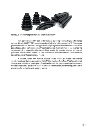
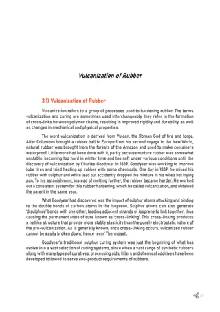
![82
3.2) Sulphur Vulcanization
Sulphur vulcanization is a chemical process that converts double bonded natural
rubber or synthetic rubbers into materials with varying hardness, elasticity and mechanical
durability by heating them with sulphur or sulphur-containing compounds. Sulphur forms
cross-linking bridges between a variety of rubber molecules, affecting the polymer’s physical
and mechanical properties. It is commonly accomplished by forming a cross-linked network
in rubber molecules, as illustrated in Figure 3.1 [1].
Figure 3.1 Cross-links by sulphur vulcanization [1]
In the sulphur vulcanization process, sulphur forms bridges between ‘cure sites’ of
selective polymer chains; ‘cure sites’ refers here to the allyl groups in the rubber molecule
(-CH=CH-CH2-). These bridges may consist of one sulphur atom (mono-sulphide) or two
sulphur atoms (di-sulphide) or many sulphide cross-links which form bridges between the
chains [2] as stress bearing members contributing to elasticity and strength. In the case of
forming cyclic sulphides, accelerator fragments and vicinal cross-links, these groups of
sulphides do not contribute to elasticity of vulcanized rubber.
Figure 3.2 Model of an “accelerated” NR-sulphur network [2]](https://image.slidesharecdn.com/worldofrubber-2022-dr-220920074909-7d531796/85/World-Of-Rubber-84-320.jpg)
![83
Cross-links with more than two sulphur atoms are referred to as ‘Sx’ (polysulphidic
cross-links). With the action of heat (at as low as 90-100ºC), ‘Sx’ is desulphurated to generate
di or mono sulfidic or poly-sulphidic cross-links, depending on the amount of sulphur,
accelerators used, temperature, pressure and time in the curing process, As shown in the
following examples, the degree of cross-linking has a significant impact on both the physical
and mechanical properties of rubber produced:
• More cross-linking makes rubber harder
• Number of sulphur atoms in the cross-linking chains affects the thermal stability,
physical and mechanical properties of rubber produced.
• Longer cross-links, with a high number of sulphur atoms, give the rubber improved
elongation, but poor weathering resistance and compression set.
•Hightemperaturevulcanizationwithhighamountsofsulphurcancausesulphurbloom
• Polymer with high level of allyl or unsaturation exhibit higher level vulcanization rate.
• In some exceptional cases, terminal vinyl unsaturation as in high-vinyl BR has a low
reactivity toward sulphur vulcanization which hardly affects CR because the Cl attaches to the
C=C unsaturated site. Halogenation of IIR to XIIR results in an enhanced reactivity towards
sulphur vulcanization with BIIR being more reactive than CIIR.
3.2.1 Mechanism of sulphur vulcanization
Elementary sulphur has a cyclic eight atom molecule at normal temperature with an
average energy of S-S bond of 252 kJ.mol-1
[3]. Naturally, sulphur exists in two forms, soluble
and insoluble sulphur. Soluble sulphur is in the rhombic state and can partially dissolve in
polymer whereas insoluble sulphur is amorphous. Soluble sulphur can easily cause blooming
because after it has dissolved in polymer, it does not form a cross-link reaction and comes
out to the polymer surface later as blooming.
The cross-link mechanism of sulphur starts from S8 opening its ring to form free
radicals, which then react with hydrogen at the secondary or tertiary carbon atom of the
polymer chains and form cross-links between two chains of polymers (Figure 3.3) [4].](https://image.slidesharecdn.com/worldofrubber-2022-dr-220920074909-7d531796/85/World-Of-Rubber-85-320.jpg)
![84
Figure 3.3 Cross-link mechanism of sulphur [4]
Vulcanization of rubber by sulphur is a time-consuming and inefficient process.
Sulphur and rubber hydrocarbon react chemically mostly at the C=C (double bonds), with
each cross-link requiring 40 to 55 sulphur atoms (in the absence of an accelerator). The
process takes approximately 5 hours to complete at 140ºC, which is inefficient by any
manufacturing standards [1]. Furthermore, vulcanized rubber products are also susceptible
to oxidative degradation and lack of the mechanical properties required for rubber products.
Moreover, accelerators, which later became components of rubber compounding formulae
and research subjects, were developed to overcome these limitations.
Table 3.1 summarizes the classification of vulcanization systems as conventional
(CV), semi-efficient (semi-EV), and efficient (EV) system depending on the level of sulphur
and accelerator-to-sulphur ratio [1, 4]. For EV vulcanization, it contains more monosulphidic
and a few poly- and di-sulphidic cross-links (Table 3.2) are preferred for better heat stability,
lower compression set, longer resist reversion, thermal aging and over-cured [1, 4]. In
comparison to the polysulphide predominant network (i.e., ~95% polysulphidic cross-links,
Table 3.2), a high accelerator/sulphur ratio curing system is required to offer a longer cure
time and a product with a high number of monosulphide cross-linking for reversion time.
Furthermore, the sulphur concentration to accelerator moiety concentration ratio for semi-EV
vulcanization is all in the intermediate (Table 3.1), which is the excellent compromise since
they have a strong unaged fatigue life that is maintained after heat aging [1].](https://image.slidesharecdn.com/worldofrubber-2022-dr-220920074909-7d531796/85/World-Of-Rubber-86-320.jpg)
![85
Vulcanization system
Sulfur
(phr)
Accelerator
(phr)
A/S ratio
Conventional (CV) 2.0-3.5 1.2-0.4 0.1-0.6
Semi-EV 1.0-1.7 2.5-1.2 0.7-2.5
Efficient (EV) 0.4-0.8 5.0-2.0 2.5-12.0
Table 3.1 Sulphur vulcanization systems and types of cross-link [4, 5]
Cure system CV
system
Semi EV
system
EV
system
Poly- and di-sulphidic cross-links, % 95 50 20
Monosulphidic cross-links, % 5 50 80
Cyclic sulphides concentration High Medium Low
Reversion resistance Low Medium High
Heat aging resistance Low Medium High
Flex-fatigue resistance High Medium Low
Heat build-up High Medium Low
Tear resistance High Medium Low
Compression set High Medium Low
Table 3.2 Effect of vulcanization system on technological properties [4]
1. The CV system performs poorly in terms of reversion, heat aging and long-term
flex resistance. However, the products have high tensile and tear strength as well as fatigue
and low temperature resistance.
2. The EV system generates thermally stable products with a network of mono- and
disulphidic cross-links. The products exhibit low tensile and tear strength, flex-fatigue life
and abrasion resistance because to the short sulphur cross-linking. However, EV systems
provide excellent heat aging and low compression set. This curing procedure is utilized for
rubber products with thick sections and those that require good static properties in use.
3. The semi-EV curing system is a compromise system between CV and EV cures
and is used in curing NR which requires heat ageing and good fatigue life.
Furthermore, rather of using a lot of accelerators to have EV and semi-EV system, it is
frequentlybettertouseasulphurdonortoreplacepartofthesulphur,suchastetramethylthiuram
disulfide (TMTD) and 4,4’-dithiodimorpholine (DTDM), among other (Table 3.3) [4]. This type
of curing system has been discovered to have good curing properties, thermal stability and
fatigue resistance [6]. There is no elemental sulphur in this vulcanization system since the
decomposition of sulphur-donor accelerator generates sulphur for cross-linking. The EV
curing system contains sulphur-donor accelerators. At the optimum cure temperature of
143ºC or 183ºC, the sulphur donor cure system offers a stable vulcanization network with
80% mono- and di-sulphidic cross-links [7].](https://image.slidesharecdn.com/worldofrubber-2022-dr-220920074909-7d531796/85/World-Of-Rubber-87-320.jpg)
![86
Table 3.3 Sulphur-donor accelerator [7]
Material Chemical structure Mol.
wt.
Melting
point, ºC
Active
sulphur, %
N,N-Captolactam
disulfide (CLD/DTDC)
2-morthilino-dithio
benzothiazole (MBSS)
Tetramethylthiuran disulfide
(TMTD)
4,4’-dithiomorpholin (DTDM)
Dipentamethylene thiuram
tetrasulfide (DPTT)
N-oxydiethylene
thiocarbamyl-N’-oxydiethylene
sulfenamide (OTOS)
224 120 11.1
284 130 11.3
240 155 13.3
236 135 13.6
384 130 16.6
284 130 12.9
3.2.2 Effect of accelerator in sulphur vulcanization
Accelerators have been used since 1906. Before the introduction of accelerators,
rubber cross-linking was done with aniline in sulphur vulcanization, as discovered by
Oenglager [8]. This method is not used commercial using because of too toxic for use in
rubber products.
The first accelerators introduced to shorten curing time were thiocarbanilide and
guanidine, but in 1919 cabondisulfide and aliphatic amines or dithiocarbamates were used [9].
However, this kind of accelerator made very short scorch time and generated problems to
some rubber parts makers. Then, the curing retardant was introduced to extend the period
for scorch safety and the molding process [9].
MBT and MBTS were used commercially in 1925 to delay the action of accelerators
and were favored in deployment of cord-ply construction in automobile tires. However,
efficient delay accelerator chemicals were introduced in 1968, when pre-vulcanization inhibitor
(PVI) and N-cyclohexyl thiopthalimide (CTP) were used as vulcanization inhibitors [10]. Before
the development of PVI and CTP, acidic retarders such as benzoic acid, acetylsalicylic acid,
salicylic acid and phthalic anhydride were used [11].](https://image.slidesharecdn.com/worldofrubber-2022-dr-220920074909-7d531796/85/World-Of-Rubber-88-320.jpg)
![87
Ingredients
Zinc oxide 2.0 – 10.0
Stearic acid 1.0 – 4.0
Accelerator 0.5 – 4.0
Sulphur 0.5 – 3.0
phr
Table 3.4 Typical sulphur vulcanization system [1]
Sulphur vulcanization with accelerators is the most used method. Zinc oxide (ZnO)
and stearic acid are activators for the vulcanization. Both chemicals can combine to generate
a salt that forms complexes with accelerators and the reaction products. Table 3.4 summarizes
a typical sulphur vulcanization system, which is listed in the table below [1].
3.2.3 Mechanism of sulphur-accelerator vulcanization
The chemistry of accelerated sulphur vulcanization is extremely complex because
several chemical reactions proceed at the same time with various reaction speeds at
the selected vulcanization temperature. Both radical and ionic process are involved, the
consequent effect is significantly reliant on the compounded [4, 12] formulations indicated
in Figure 3.4.](https://image.slidesharecdn.com/worldofrubber-2022-dr-220920074909-7d531796/85/World-Of-Rubber-89-320.jpg)
![88
B. Ionic mechanism:
Figure 3.4 Radical (A) and ionic (B) mechanisms of sulphur vulcanization [4, 12]
A. Redical mechanism:
(I) The creation of ‘Accelerator-polysulphide’ by reaction of ‘Accelerator-polysulphide’
is the first stage in sulphur vulcanization
Accelerator + Zinc Oxide + Stearic acid + Sulphur](https://image.slidesharecdn.com/worldofrubber-2022-dr-220920074909-7d531796/85/World-Of-Rubber-90-320.jpg)
![89
(II) The reactions can be divided into three kinds of complex substances A, B and C
as shown below:
(III) In the accelerator-polysulphide, Zn may also form a combination with sulphur,
as seen below:
All of these compounds can sulphurate rubber chains and are classified as active
sulphurating agents [13].
The relation between compounded formulation and reaction type is shown in the
Table 3.5.](https://image.slidesharecdn.com/worldofrubber-2022-dr-220920074909-7d531796/85/World-Of-Rubber-91-320.jpg)
![90
Type of mechanism Cure system
Radical NR + CBS + Sulphur
NR + TMTD + Sulphur
NR + TMTD
NR + Sulphur
Ionic NR + TMTD + Sulphur + ZnO + St. acid
NR + TMTD + ZnO
Mixed (Radical + Ionic) NR + CBS + Sulphur + ZnO + St. acid
Table 3.5 Type of reactions [14-17]
Accelerators Chemical group Vulcanization speed
BA, HMT Aldehyde group Slow
DPG, DOTG Guanidine Slow
MBT, MBTS, ZMBT Thiazole Semi Ultra fast
ZBDP Thiophosphate Ultra fast
CBS, TBBS, MBS, DCBS Sulfenamides Fast-Delayed action
ETU, DPTU, DBTU Thiourea Ultra fast
TMTM, TMTD, DPTT, TBzTD Thiuram Ultra fast
ZDMC, ZDEC, ZDBC, ZBEC Dithiocarbamate Ultra fast
ZIX
Xanthates Ultra fast
Table 3.6 Classification of accelerators their relative vulcanization rates [12]
During the cross-link reaction, three competing reactions occur simultaneously
during vulcanization, including [18]:
y Cross-linking
y Cross-linking desulphuration
y Main chain modifications (i.e., dehydrogenation and cyclic sulphide formation)
3.2.4 Types of Accelerators
Each chemical group can give different vulcanization speed, different cross-link
density and scorch safety as shown in the Table 3.6.](https://image.slidesharecdn.com/worldofrubber-2022-dr-220920074909-7d531796/85/World-Of-Rubber-92-320.jpg)
![91
Figure 3.5 Characteristic of accelerators [17]
3.2.5 Cross-link density and vulcanizate properties
The number of molecules of cross-linked units per unit weight of the cross-linked
polymer is referred to cross-link density. The cross-linked level is calculated by dividing the
number of molecules of cross-linked basic units by the total number of polymer basic units.
The cross-link density of rubber vulcanizate has a significant impact on its properties [1].
Various properties such as static modulus, dynamic modulus and hardness increased as
cross-link density increased. Furthermore, when cross-link density decrease, fracture
properties such as tensile strength and tear strength peak before declining. It should be
noted that the attributes shown in Figure 3.6 are influenced not only by the cross-link level,
but also affected by the types of polymer, cross-link and filler loading [1].](https://image.slidesharecdn.com/worldofrubber-2022-dr-220920074909-7d531796/85/World-Of-Rubber-93-320.jpg)
![92
Figure 3.6 Vulcanizate properties as a function of the extent of vulcanization [11]
The tensile strength of the vulcanizate is related to the average molecular weight of
the polymer between two adjacent cross-links (Mc). When un-vulcanized rubber is stressed,
the rubber molecules detangling (slip). The fracture occurs at low stress by viscous flow at a
lower rate without breaking any chemical bonds. A few cross-links increases the molecular
weight of the rubber molecules, resulting in a branched molecule with a broader molecular
weight distribution (MWD). Detangling the branched chains becomes more difficult as a result,
enhancing the tensile strength of the vulcanizate.
Rubbers have an optimal cross-link density range for their practical application.
The cross-link level must be high enough to prevent viscous flow fracture while remaining
low enough to avoid brittleness. As a result, the degree and type of cross-links are the most
important factor in achieving the desired vulcanizate properties. Several factors influence the
type of cross-link formed, including sulphur level, accelerator type, accelerator-ratio-sulphur
and cure time.
In general, a higher accelerator/sulphur ratio and a longer cure time promote the
formation of monosulphide cross-link formation at the expense of polysulphide cross-links.
Because C-S are more stable than S-S bonds, rubber vulcanizates with polysulphide
cross-link provide better heat stability, lower compression set and longer reversion time than
polysulphide predominant networks. In addition, the rubber vulcanizates containing higher
proportions of polysulphide cross-links most provide enhanced tensile and tear strength as
well as flex-fatigue resistance, due to the possibility for S-S bonds to break reversibly and
so locally release high stresses that could initiate failure.](https://image.slidesharecdn.com/worldofrubber-2022-dr-220920074909-7d531796/85/World-Of-Rubber-94-320.jpg)
![93
3.2.6 To improve the storage and curing scorch technique
Sulfenamide accelerator can be used to delay scorch time of natural rubber
cross-links. The three major aspects which decide the activity of a sulfenamide are:
- Amine group in sulfenamide with steric hindrance structure delays the scorch time.
Basicity of steric hindering of the amine group offers scorch delay and slower cure rates.
Amine group, the shorter the scorch time and the faster is the cure rate.
- The bond strength of S-N in sulfenamide delays the scorch time.
- The presence of MBT, as shown in Figure 3.7 [17], is first generated by the thermal
decomposition of sulfenamide (CBS) accelerator [19]. The formed MBT is immediately converted
to MBTS. Furthermore, the reaction of the remaining CBS with MBT to create MBTS was
observed during the induction period [19]. These reactions give the scorch delay generated
by sulfenamide accelerator [20].
Figure 3.7 MBTS accelerated sulphur vulcanization [1, 17]](https://image.slidesharecdn.com/worldofrubber-2022-dr-220920074909-7d531796/85/World-Of-Rubber-95-320.jpg)
![94
(I) Organic peroxides with carboxylic groups
(II) Organic peroxides without carboxylic groups
‹Classification of organic peroxides
In the absence of PVI, sulfenamide accelerator decomposes into MBT and amine,
with the MBT releasing the sulfenamide accelerator via autocatalytic decomposition. Sulphur
cross-linking does not occur as long as the sulfenamide accelerator level is not decreased.
After forming active sulphurating agent, sulphurated rubber and pendant groups, MBT is
converted to MBTS for cross-linking.
Sulphur vulcanization can increase the efficiency of adhesion (adhesive strength)
between rubber and copper. In tire production, adhesive strength between steel cord and
rubber is necessary when manufacturing high performance steel-cord tires. With sulfenamide
accelerator, a thin film of copper sulfide is formed and promotes good adhesion and cohesion
between copper and rubber. Cohesive strength occurs within the sulfide film and a layer below
the sulfide film but the sulfide film must completely form before cross-linking starts. Retarder
CTP or DCBS is added to delay the action of the accelerator and cross-linking. Furthermore,
benzothiazoles and sulfenamides are commonly applied in the process of copper adhesion.
3.3) Organic Peroxides Vulcanization
Organic peroxides can vulcanize most elastomers that contain saturated and
unsaturated bonds. They were first used in 1915 by Ostromyslenskij using dibenzoyl peroxide
with NR [21]. Nowadays, they are used as vulcanization agents of rubbers if temperature
resistance is required, or to vulcanize rubber compounds consisting of a combination of
saturated and unsaturated rubbers.
The peroxide that is most suitable for cross-linking rubber is the peroxide group
that is fixed to a tertiary carbon. Peroxides with the peroxide group fixed to primary or
secondary carbon are less stable. Example; since dibenzoyl peroxide has carboxyl groups in
the molecule, the rate of its decomposition is increased by the oxygen. This kind of peroxide
it is not suitable for rubber compounding because its decomposition temperature is 130ºC,
which is too low for normal rubber processing.](https://image.slidesharecdn.com/worldofrubber-2022-dr-220920074909-7d531796/85/World-Of-Rubber-96-320.jpg)
![95
(III) Organic peroxides with mixed structure
(IV) Organic peroxides polymeric
Vulcanization by peroxide is normally done at temperature ranging of 140ºC to 180ºC.
Compared with sulphur curing, rubber products cured by organic peroxide have good
resistance to temperature and good electrical properties. But these finished products have
some weak physical and mechanical properties i.e., less elastic and worse in dynamic
properties, tensile strength, structural resistance and resistance to wear.
Dialkyl peroxide with t-butyl perbenzoate gives good performance rubber products,
but di-t-butyl peroxide and dicumyl peroxide generate volatile acetophenone with its strong
odor during the process. 1,1-bis(t-butylperoxy)-3,3,5-trimethylcyclo-hexane and 2,5-dimethyl-
2-5-bis(t-butyl-peroxy) hexane are suggested to be used to avoid an unpleasant odor during
the process.
3.3.1 Peroxide vulcanization mechanism
The oxygen-oxygen bonds in the chemical structure of an organic peroxide can
be easily broken by heat to generate two free radicals (*). These radicals are unstable and
very reactive. They react with the weak carbon-hydrogen bond of the polymer to transfer
radicals to the hydrogen chain, forming hydrocarbon radicals which are very active [22]. It is
dehydrogenation reaction in which two active hydrocarbon radicals share free radical
electrons to form a cross-linking chain. In general, the first place to be affected in the rubber
molecule is the alpha-methylene carbon atom.
Since the covalent bond of carbon-carbon (350 kJ) is stronger than carbon-sulphur
(270 kJ) bond, the stronger C-C bond requires higher energy to break the bond. Therefore,
peroxide vulcanized rubbers provide better heat resistance and better compression set than
rubber products that are vulcanized by sulphur curing systems [3]. The general scheme for
organic peroxide cure of elastomer is shown in Figure 3.8 [23].](https://image.slidesharecdn.com/worldofrubber-2022-dr-220920074909-7d531796/85/World-Of-Rubber-97-320.jpg)
![96
Figure 3.8 Peroxide cross-linking of elastomer [23, 24]
In general, the first place to be affected in rubber molecule is alpha-methylene
carbon atom.
Example:
Peroxide vulcanization systems are relatively more expensive than the sulphur curing
systems and have some limitations. Most of the antioxidants used in rubber compounds
retard or decrease the vulcanization performance of the peroxide cross-links reaction. Acidic
compounds that contain fatty acid, carbon black or silica can catalyze and retard the radical
generation in the peroxide curing process. They slow down the half-time of decomposition
of peroxide at the vulcanization temperature, which decreases the cross-link density.
It should be noted that, peroxide cannot be used for cross-linking butyl rubber,
because the tertiary carbon of butyl rubber will generate more chain scission than the
cross-linking by peroxide.](https://image.slidesharecdn.com/worldofrubber-2022-dr-220920074909-7d531796/85/World-Of-Rubber-98-320.jpg)
![97
Table 3.7 Examples of some commercial peroxides
Note: The temperature required to decompose half of a peroxide sample in ten hours.
Peroxide trade name Chemical name
10 hr.
half-life
temp. (ºC)
Processing
temp. (ºC)
Typical cure
temp. (ºC)
Cross-linking
efficiency (%)
Luperox 103
Trigonox 145
Perhexyne 25B
Luperrox 101
Perhexa 25B
Varox DBPH
Luperox F
Perkadox 14
VulCup
Perkadox BC
DiCup
Varox DCP
Luperox 231-XL
Triganox 29
Perkadox 3M
128 150 195 30
119 130 185 41
117 130 180 52
115 120 170 50
92 110 150 21
2,5-Dimethyl-2,
5-di(t-butylperoxy)
hexyne-3
2,5-Di-methyl-2,
5-di(t-butylperoxy)
hexane
1,3 Bis-(t-butylp-
eroxy-iso-propyl)
benzene
Di-cumylperoxide
1,1-Di-t-butyl-
peroxy-3,3,5-
trimethylcyclohexane
Table 3.8 Advantages and disadvantages of peroxide cure over sulphur cure [3]
*The temperature required to decompose one half of a peroxide sample in ten hours.
Advantage Disadvantage
• Simple formulation, long term compound storage
stability and possibility of using higher processing
temperatures.
• Rapid cure at high temperature and yet no reversion.
• Low compression and permanent set, higher
temperatureresistanceandnoextractableconstituents.
• Non-staining, non-blooming and non-discoloring.
• Co-vulcanizationofsaturatedandunsaturatedrubbers.
• Selecting suitable co-agents. Properties of rubber
products can improve, such as tensile strength, tear
strength, flex- fatigue resistance, and abrasion.
• Sensitivity to oxygen during cure.
• Process oils, antioxidants, resins, acidic clays
andotheracidicmaterialsusedincompounding
canaffectperoxidecuredproductssignificantly.
• Properties of vulcanized products such as
tensile strength, tear strength, flex-fatigue
resistance, abrasion, etc. are significantly
affected.
• Unpleasantodoroccursduringprocessaswell
as in the cured products in some cases.
• Longer cure time and need higher curing
temperatures. Post cures are necessary in
most cases.
• Higher cost of peroxides and vulcanization
process.](https://image.slidesharecdn.com/worldofrubber-2022-dr-220920074909-7d531796/85/World-Of-Rubber-99-320.jpg)
![98
3.3.2 Co-agents in peroxide vulcanization
Because of drawbacks in physical and mechanical properties from organic peroxide
curing, peroxide curing with coagents has been developed to improve those properties.
Efficiency of peroxide cross-linking increases by using co-agents such as (meth)acrylates
and polyolefin with bi- or multi-functional double bonds like allylic and vinyl or derivatives
of maleic acid. These products increase the cross-link density and improve physical and
mechanical properties of the final products. These co-agents also act as the plasticizer and
improve processing.
Co-agents are multi-functional organic molecules which are highly reactive towards
free radicals. They are used as reactive additives to boost peroxide vulcanization efficiency.
The most commonly used co-agents are organic chemicals with (meth)acrylate groups,
maleimide groups or allylic groups and polymeric materials with a high vinyl content (i.e.,
1,2-polybutadiene).
In the absence of co-agents, the efficiency of peroxide curing system is rather low
due to the presence of side reactions that consume radicals. Co-agents can significantly
increase peroxide efficiency by preventing inefficient side reactions such as cleavage (or
chain scission) and disproportionation. Co-agents will form coagent bridges or bonds
between polymer chains as extra cross-links. Those are the reasons why coagents increase
cross-linking efficiency and improve physical and mechanical properties of final rubber
products. According to their contribution to the vulcanization process, co-agents can be
classified into two types: type I and type II [25, 26].
(I) Type I: addition and hydrogen abstraction
Type I co-agents are polar molecules with a low molecular weight. Their main
characteristic is that they are extremely reactive towards radicals, therefore scorch occurs
suddenly. The benefit of using these co-agents is that they not only increase the rate of cure,
but also increases cross-link density [27].
Type I co-agents generally have reactive free radicals which increase both the rate
of cure and the state of cure of the system. These co-agents are mostly low molecular weight
polar molecules which are capable of homo-polymerization as well as grafting i.e., acrylate
and methacrylate ester. N,N’-m-phenylenedimaleimide can also react with in-chain
unsaturation through an “ene” reaction mechanism.
Type I co-agents include methacrylates, acrylates, bismaleimides and zinc salts [3].](https://image.slidesharecdn.com/worldofrubber-2022-dr-220920074909-7d531796/85/World-Of-Rubber-100-320.jpg)
![99
Figure 3.9 Type I coagents [3]
Figure 3.10 Type II co-agents
(II) Type II: addition reactions
Because type II coagent have less polar molecules, they generate less scorch than
type I and reactions take longer. These co-agents improve the cross-link density but do not
increase the cure rate [27]. Due to their low polarity, these co-agents have good compatibility
with many elastomers and work as good processing aids.
Examples of Type II coagents are high-vinyl 1,2-polybutadiene, divinylbenzene, allyl
esters of cyanurates, isocyanurates and allyl phosphate.](https://image.slidesharecdn.com/worldofrubber-2022-dr-220920074909-7d531796/85/World-Of-Rubber-101-320.jpg)
![100
Figure 3.11 Peroxide cross-link of rubber molecule [28]
Type II co-agents are less reactive (more stable) and primarily increase the
elastomer’s state of cure. The co-agents generate bridges between rubber molecules,
increasing cross-linking efficiency by generating extra cross-links. Further, they have a
major affinity for radicals, which acids in the reduction of chain scission and disproportionation
reactions. When co-agents are added to a peroxide curing system, the following benefits are
obtained [25, 28-30]:
¾ Improved peroxide efficiency
¾ Improved mechanical properties such as modulus, tensile strength and hardness
¾ Enhance compression set (i.e., lower compression set)
¾ Improved resilience
¾ Lower viscosity of rubber compound
¾ Good oil and fuels resistance
¾ Good heat ageing
¾ Improved the adhesion properties of rubber coating to metal (in the case of zinc
salts)
¾ Enhanced dynamic properties
3.3.3 Mechanism of coagent reaction
The general cure mechanism of peroxide/coagents cure is as below:](https://image.slidesharecdn.com/worldofrubber-2022-dr-220920074909-7d531796/85/World-Of-Rubber-102-320.jpg)
![101
Figure 3.12 Cross-linked network structure of rubber matrix cured with peroxide in the presence
of co-agent; a) No coagent only peroxide; b) Use of coagent compatible with the matrix; C) Use
of coagent not fully compatible with the matrix, formation of filler like domains [27]
Figure 3.13 Reaction mechanism of certain Type I co-agents with elastomers [31]
However, the nature and quality of the cross-link can be tailor-made, depending on
the elastomer and the nature of the coagents.
Type I coagents can homo-polymerize and/or graft onto macroradicals, forming
effective cross-links (or higher cross-link density) via radical addition reactions as seen in
Figure 3.12 [31].
Type II coagents, containing extractable allylic hydrogens participate in intramolecular
cyclization reactions as well as intermolecular propagation reactions [32, 33]. Trifunctional
coagents (TAC and TAIC) may form cross-links through the cyclo-polymerization products
as well as grafting through pendant allyl groups [32]. The polymeric co-agents with high
vinyl microstructure enhance the concentration of reactive pendant unsaturation, resulting in
encouraging cross-linking reactions [32]. The mechanism shown below (Figure 3.14) explains
how an allyl containing co-agent is incorporated into the rubber molecules [34].](https://image.slidesharecdn.com/worldofrubber-2022-dr-220920074909-7d531796/85/World-Of-Rubber-103-320.jpg)
![102
Figure 3.14 Possible reaction mechanism of Type II co-agents suggested by Endstra [34]
Figure 3.15 Cure characteristics of standard peroxide cure (A), that using type I coagents (B)
and type II coagents (C) [35]
Figure 3.15 shows cure characteristics of standard peroxide cure (A), that using type
I coagents (B) and type II coagents (C) [35]. In a typical peroxide curing system, the reactive
Type I coagents reduce scorch time (ts2*) but increase cure time (t90*). Furthermore, type II
coagents provide the scorch safety. Also, for both type I and II coagents, the extent of cure
(S*
) is frequently increased as more effective cross-links are created [35].](https://image.slidesharecdn.com/worldofrubber-2022-dr-220920074909-7d531796/85/World-Of-Rubber-104-320.jpg)
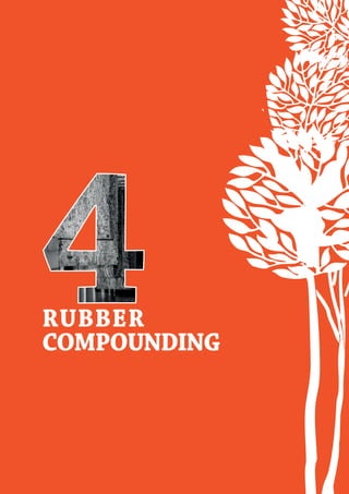
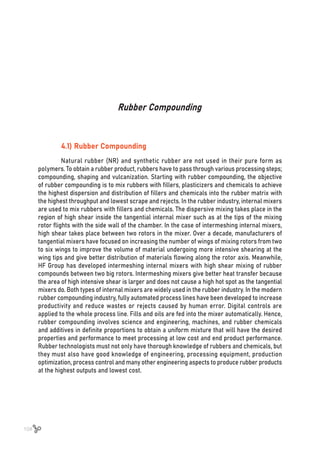
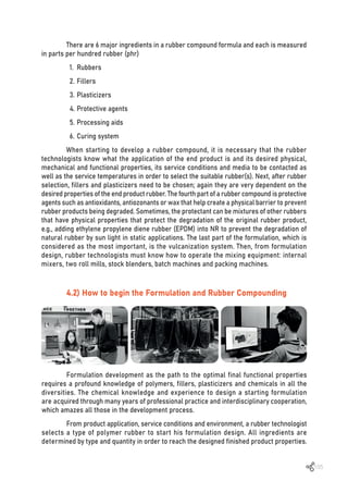
![106
Figure 4.1 Elastomers positioned by their resistance to heat aging and swelling in IRM 903
oil, according to ASTM D2000 [1]
The selection of polymer rubber under the respective boundary conditions and requirements
is important based on:
1. Service conditions of rubber final product in its service environmental such as
light, ozone and weathering conditions, upper and lower temperatures of service,
contact with what types of media.
2. Mechanical and dynamic properties required.
3. Compounding processing technology.
4. Processing method and equipment to produce rubber parts.
5. Final product inspection and testing
4.2.1 Formulation design
Let’s start with rubber selection. As previously work, all rubber technologists are
familiar with the heat-oil resistance chart or ASTM D 2000 [1].
Rubber technologists must have full knowledge of rubbers and their chemical
structures to determine rubber properties. From the above table, a group of hydrocarbon
rubbers at the left hand corner of the chart i.e., NR, styrene butadiene rubber (SBR), butadiene
rubber (BR), and butyl rubber (IIR) are a group of hydrocarbon rubbers with diene in their
structures. These rubbers have poor resistance to oil and ozone. Service temperatures of
these rubbers must be low (below 60ºC). These hydrocarbon rubbers are used mainly in the
tire and footwear industries, which together consume almost 70% of the total rubber produced.](https://image.slidesharecdn.com/worldofrubber-2022-dr-220920074909-7d531796/85/World-Of-Rubber-108-320.jpg)
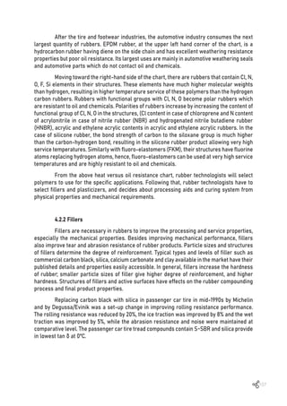
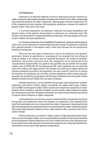
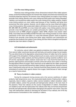
![110
A. Effect of heat
Temperatures is a key factor of degradation of rubbers because of oxidation (heat
oxidation). Generally, there are two conditions that will elevate the temperature of rubbers
and rubber products and generate rubber degradation.
(I) Antioxidants of phosphate derivatives are designed to protect rubbers during
the mixing step and curing step. They are burned up during the high temperature mixing and
vulcanization periods.
(II) Stress applied to rubber products during the intended use. Antioxidants
containing amines and amine derivatives are designed to provide anti-flex cracking properties
to rubber products
B. Effect of UV light
Degradation of rubbers can be triggered by UV light. This degradation can be retarded
with UV stabilizers. The hindered amine light stabilisers (HALS) are chemical compounds
containing an amine functional group that are used as stabilizers in polymer [2]. Furthermore,
phenols are commonly used in combination with secondary antioxidants and UV light stabilizers.
Because they are photostable [3].
C. Effect of oxidation on polymers
Upon oxidation, rubber products will become soft and tacky or hard and brittle. This
is the cause of polymer chain scissions or cross-linking hardening. This can happen in
isoprene rubber, natural rubber butyl rubber or even the polar rubber ‘G’ type of neoprene.
NBR and SBR rubbers and some types of polymer become hardened or undergo cross-linking.
Non-polar saturated polymers such as EPDM or EPM and silicone are used as anti-degradants
to protect rubber products from oxidation. Example, blending 25-30 phr of EPDM to natural
rubber or a system of isoprene rubbers, will significantly retard the oxidation of the rubber
products. EPDM also retards UV degradation of natural rubber and isoprene rubber.
‹ Ozone degradation
Rubber can be degraded by ozone attack, because ozone directly attacks the
carbon-carbon double bonds of the rubbers. Only polymers having backbone unsaturation
were found to be fractured by ozone [4]. Unlike oxidation, ozone degradation cannot be
accelerated by increasing the temperature. It is produced when polymer stretches, bur cracks
do not form if the underlying double carbon-carbon boundary is not exposed to ozone. Ozone
cracking is a physicochemical phenomenon that occurs when polymer chains are attack,
resulting in chain scission and the formation of decomposition product [5, 6]. The formation
of a relatively unstable ozonide, which cleaves to form an aldehyde or ketone and a carbonyl
group, is the initial step in the process [5, 6]. Following that, the aldehyde and carbonyl
groups recombine to form a second ozonide. Furthermore, due to the attack of the carbonyl
groups generated by primary ozonide cleavage on the rubber carbon-carbon double bonds,
cross-linking and chain scission may form during rubber ozonation, especially in IR, IIR and
SBR [5, 6]. These rubbers (i.e., IR, IIR and SBR) are more prone to produce chain scission
product or crack at the deactivated double carbon-carbon bonds.](https://image.slidesharecdn.com/worldofrubber-2022-dr-220920074909-7d531796/85/World-Of-Rubber-112-320.jpg)
![111
Antiozonant should have two functions: they should reduce the rate of crack growth
in the rubber and decrease the critical stress value (i.e., the stress at which crack growth
occurs) [4, 7]
1) Effective antiozonant provides an effective barrier against the penetration of ozone
at the rubber surface.
2) Antiozonant must be very reactive with ozone.
3) Since ozone attack is at the surface of rubber, antiozonant should have adequate
solubility and diffusivity with the rubber and must migrate to the surface of the rubber to
prevent ozone attack. Poor solubility in rubber may result in excessive bloom of antiozonants.
4) Antiozonant must not have adverse effects to the rubber processing and physical
and mechanical properties of rubbers.
5) Antiozonants must have low toxicity and not discolor or stain the rubber products.
Hydrocarbon waxes and blends of paraffins with micro-waxes are common types of
physical antiozonants; p-phenylenediamine derivatives are the prevalent chemical antiozonants.
Waxes migrate to the rubber surface and form a protective barrier which remains stable at
temperatures from -10ºC to above 50ºC. 1-2 phr of microcrystalline waxes are recommended
for applications where rubber products are used. In conditions which involve continuous
flexing, p-phenylenediamines (N,N alkyl-aryl derivatives) are recommended. These chemicals
scavenge the ozone before it attacks the rubbers, forming an ionized products that protects
both the rubber and antiozonants from further attack. However, the p-phenylenediamines
are staining chemicals to the rubber compounds. Whenever color is a concern, blends of
saturated elastomers at a high level of 30 phr are commonly seen to provide sufficient
effectiveness. Furthermore, for long periods of static and dynamic stresses, the combination
of antiozonants in rubber compounds total 1.5-3.0 phr of waxes and chemical antiozonants.
4.2.6 Processing aids
Processing aids are resins used to improve compatibility of dissimilar elastomers
and improve mixing, processing and surface track. Homogenizers are used when compounding
dissimilar rubber polymer, such as mixing natural rubber and halobutyl rubber (HIIR) in side-wall
compounds of tire processing. Various grades of homogenizers also improve surface
appearance and filler incorporation resulting in reduction of compound viscosity and energy
consumption in mixing [7].](https://image.slidesharecdn.com/worldofrubber-2022-dr-220920074909-7d531796/85/World-Of-Rubber-113-320.jpg)
![112
4.3) Compounding Equipment
Previously, two roll mills were used to mix rubber, filler and other ingredients. However,
this is extremely time consuming and not viable in today’s commercial manufacturing. When a
large quantity needs to be mixed efficiently, internal mixers are used.
4.3.1 Two roll mill
Mixed compounds from the internal mixers will drop on to the two roll mill
underneath, which will enhance the distribution of fillers and chemicals into the compound
matrix. Stock blenders are sometimes installed to speed up mixing time at the two roll mill
and give better distribution of fillers and chemicals in the compounds. Compound from this
mixing step, is called rubber compound A. It is the rubber compound before curing.
Figure 4.2 Two roll mill [13]
‹ Compound B Mixing
Compound A is cooled down and transferred to the other mixing line. A Kneader
mixer is commonly used because it gives a low shear force which does not generate high
mixing heat. Sulphur and accelerators are mixed in the Kneader. A Kneader is different from
a Banbury and an intermeshing mixer, as the mixed compound is discharged through a side
discharge door. Mixed compound will be further mixed in a two roll mill to give excellent
distribution of chemicals into the final rubber compound which is called rubber compound B.
This compound will be ready to be delivered to the rubber part manufacturing unit.](https://image.slidesharecdn.com/worldofrubber-2022-dr-220920074909-7d531796/85/World-Of-Rubber-114-320.jpg)
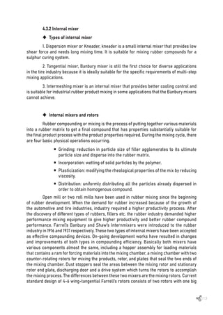
![114
Figure 4.3 Basic physical operation of tangential mixer in mixing rubber compounds [8]
pushing wing which joins with 3 or 5 smaller counter pushing wings. Each wing has a narrow
tip. Two rotors are fixed in the mixer and the space between rotors and chamber wall has a
narrow fixed clearance. Functions of the pushing wing are to disperse and distribute fillers
and chemicals into the rubber. Small wings help in turning the mixing compounds from side
to side and to the other chamber (distribution). Shearing happens in the area of rotors with
the wall of the chamber (Figures 4.3 and 4.4). The basic physical operation in tangential
mixers in mixing rubber compounds is to incorporate polymer with filler and chemicals and
distribute the additives evenly in the whole compound (dispersion and distribution). In a
tangential rotors (Figure 4.5) of internal mixer, the high shear zone is the small area between
the chamber wall and the rotating rotor’s tip. The design of intermeshing rotors (Figure 4.5)
consists of two big rotors on each of which are one long uninterrupted wing (long wing) and
two small wings (called islands). Mixing or dispersion happens between the narrow gap of
the two big wings. Regarding the distribution of mixing compound, the long wings push the
mixing material in the axial direction which the small islands push the mixing material into
the other chamber (see Figures 4.3 and 4.4).](https://image.slidesharecdn.com/worldofrubber-2022-dr-220920074909-7d531796/85/World-Of-Rubber-116-320.jpg)
![115
Figure 4.4 Filler incorporation, dispersion and distribution in Intermeshing mixers [8]
Figure 4.5 Intermeshing and tangential rotors of internal mixer [9, 10]
In the tire industry, tangential mixers have been used because of higher loading
factors than the intermeshing mixers. However, intermeshing mixers are gaining more
acceptance in mixing industrial compounds which need higher performance rubber
compounds in producing precision rubber parts. Today’s tread compounds are based on S-SBR
mixed with highly disposable precipitated silica; to achieve the good compound properties,
intermeshing mixers are more preferable](https://image.slidesharecdn.com/worldofrubber-2022-dr-220920074909-7d531796/85/World-Of-Rubber-117-320.jpg)
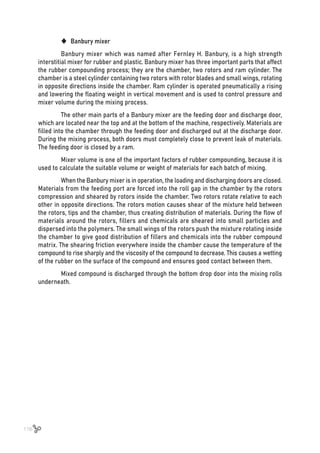
![117
Figure 4.6 Banbury mixer [11, 12]
‹ How to use the Banbury mixer
Fill factor, ram pressure, rotor speed, coolant temperature, and design of rubber
mixing (i.e., fill factor and mixing sequence, time together with the number of passes through
the mixer) are all machine-related parameters that influence the properties of rubber
compounds. These related parameters have a directly impact on the level of carbon black
dispersion of the rubber compound at the final stage of rubber process.
• Ram pressure: the pressure applied to the ram during rubber mixing must
be regulated to ensure that rubber and other ingredients in the mixer engage rapidly with
the rotors. This will also prevent any subsequent up thrust of the batch.
• Rotor speed and design: the rotor speed can be adjusted to achieve good
dispersion quickly. The sequence of mixing step is related to the design of the rotors in order
to maximize mixing time and quality.
• Fill factor: the fill factor can adjust to meet a particular mixture’s specifications.
Ifthefillfactoristoohigh,partsofthebatchmayavoidshearmixing,resultinginnon-homogeneity
of the material and ingredients or poor dispersion in the rubber compound. Conversely, if the fill
factor is too low, voids will occur in the rubber compound behind the rotor wing.
• Coolant temperature: the mixing temperature must be controlled to a specific
level depending on type of rubber compound. If the mixing chamber is not appropriately cooled
during mixing, there may rise rapidly, causing scorch problem for the rubber compound.
Furthermore, as the temperature increased, the rubber chains to break down into segmental
moieties.Thiscouldhaveanegativeimpactonthemechanicalpropertiesoftherubbercompound.](https://image.slidesharecdn.com/worldofrubber-2022-dr-220920074909-7d531796/85/World-Of-Rubber-119-320.jpg)
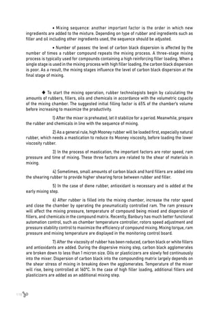
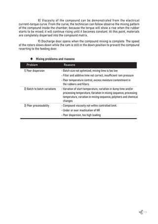

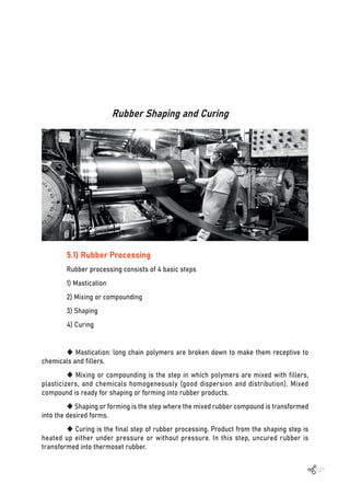
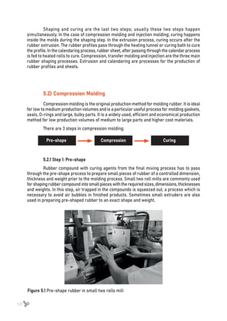
![124
Figure 5.3 Hydraulic compression molding machine [1]
‹ Transfer molding
This process is suitable to mold rubber parts that are more complicated than
compression molding can handle. It is a combination of injection and compression molding.
During the process, rubber compound is placed in the heating transfer-pot to warm and
soften. Soft rubber from the transfer-pot is pushed down from the transfer-pot through the
sprues into the cavities of the mold. Compound is cured under the heat, pressure and time
as required. Rubber products are removed from the molds ready for the finishing process.
The disadvantage of this process is the time wasted in cleaning the upper part of the molding
after operation to remove rubber scrap.
Figure 5.4 Transfer molding [2]](https://image.slidesharecdn.com/worldofrubber-2022-dr-220920074909-7d531796/85/World-Of-Rubber-126-320.jpg)
![125
‹ Injection molding
Rubber compounds are produced by feeding rubber as a continuous ribbon. Rubber
in the ribbon is continuously pulled into the feeding chamber by the screw. In the heating
chamber, rubber is heated and softened. It is forced into the injection chamber and injected into
the mold. Temperatures of screw unit, injection unit and nozzle are controlled at temperatures
below T10 of rubber compound to prevent rubber scorch. Soft rubber compound is pushed into
the cavities of the mold, where rubber is cured under the preset temperature, pressure and
time. Advantages of injection molding over the compression molding are the better dimensions
and shorter cycle times. Injection molding can also be used for thermoplastic elastomers.
Figure 5.5 Rubber injection molding machine [3]
Cylinder and screw are the main parts of an injection machine. Rubber compound is
conveyed into the cylinder through the throat by the driving screw. Rubber is softened inside
the heated cylinder while the screw drives the soft rubber compound slowly down the cylinder.
Then it is injected into the rubber mold beneath. Temperature control of the compound at the
cylinder is crucial to prevent rubber scorch.](https://image.slidesharecdn.com/worldofrubber-2022-dr-220920074909-7d531796/85/World-Of-Rubber-127-320.jpg)
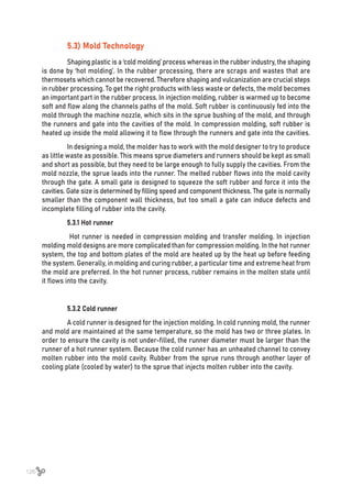
![127
Figure 5.6 Cold runner mold in injection molding [4]
5.4) Rubber Extrusion Process
Rubber extrusion is the process of turning rubber materials into long profiles or
tubes by using extruder machines. The extruder machine has two main parts: the screws
that push the stock while it is being heated in the conveyer channel and the other part is the
hopper from where the rubber stock is sent to the conveyor. In the conveyor, rubber stock is
softened through heating, shearing and pressurized by the screw rotating. The pressurized stock
is pushed into the die which is located at the end of the extruder. As it emerges, it acquires
its required shape. Extrusion is a continuous process that can produce finished products of
different lengths in a variety of shapes. Some of the products from extrusion process are
door and window seals, edge trim profile, hoses and tubes.
The conventional simple screw extruder has various zones:
ƒ Feeding zone is where the continuing rubber compound is input.
ƒ Solid conveying zone is to transport the rubber compound and slightly compress it.
ƒ Plasticating zone where rubber stock is softened to become viscous plastomer.
Viscous rubber is pushed through the barrel to the die
ƒ Die forming where the rubber is formed into the required shape of the extrudate.
At the end of the extruder, extrudate is conveyed into the rubber curing system to
cure the rubber. Microwave, hot air vulcanization, salt bath, (HAV) and steam cure are four
common curing systems used in the rubber extrusion process. Microwave cures the rubber
from inside out quickly and evenly. Salt bath has good heat exchange properties and can be
used for highly cured products and as a short-length curing unit. HAV system is a continuous
process that gives uniform curing at high production speed. While autoclave or steam cure
is used in a discontinuous (or batch) process.](https://image.slidesharecdn.com/worldofrubber-2022-dr-220920074909-7d531796/85/World-Of-Rubber-129-320.jpg)
![129
Sponge Rubber
6.1) What is Sponge Rubber?
Sponge rubber is a rubber product which contains a large number of tiny foam
holes inside the rubber matrix. Sponge rubber is usually soft and provides good cushioning,
thermal and noise insulation and has a quick recovery property. It can be either in closed
cell or open-cell structures (or the mixture of both). Open-cell sponge rubber contains open
interconnected pockets that permit the passage of air, water, gases and chemicals. Most of
the cushioning sponge rubbers have open-cell structure, while sponge rubbers used in shock
absorption, vibration damping and weathering strips have closed cell structure. Sponge rubber
was first produced in 1929 by E.A [1, 2]. Murphy and Eric Owen, researchers at Dunlop Rubber,
who whipped latex and isocyanate together to make an open-cell foam for a mattress. In
the 1950s, polyether polyurethane-based foams were developed by Charles C. Price [2, 3].
Polyurethane foam is widely used in construction, transportation, home furniture and noise
insulation. Neoprene, EPDM, nitrile rubber and ethylene vinyl acetate (EVA) resin are used in
closed cell sponge rubber. Neoprene sponge rubber is commonly used in wet-suites because
of good weathering and tear resistance properties of Neoprene. EPDM is widely used in
automotive weathering strip, construction and industrial insulations because of good weathering
resistance of EPDM. EVA foam is used widely as the midsole of shoes because it has low
compression set property. Silicon foam sponge rubber has low temperature applications, as
low as -65ºF, while fluorosilicone foam can be used in temperature going down to -80ºF.
6.2) How to produce Open and Closed-cell Sponge Rubber?
To produce open-cell sponge rubber, sodium bicarbonate is normally used as the
source of gas. It is added to the polymer compound which contains other components and a
curing system. When the polymer compound is heated up, sodium bicarbonate decomposes
and carbon dioxide gas is released, creating open, interconnected cell-foam. In the case of
closed-cell sponge rubber, blowing agents are used to produce gas bubbles in the closed cell
foams [4]. When polymer compound containing blowing agent and curing system is heated
up in the steel mold, the blowing agent decomposes to generate gas bubbles and these tiny
bubbles are trapped inside the matrix of the cross-linking rubber. Each of these cells formed
in the matrix of polymer is isolated from its neighbors. In the process, two chemical reactions](https://image.slidesharecdn.com/worldofrubber-2022-dr-220920074909-7d531796/85/World-Of-Rubber-131-320.jpg)
![130
happen simultaneously; gas generated from the decomposition of the blowing agent and a
cross-linking reaction also. Controlling the time of decomposition of blowing agent while the
cross-linking reaction is happening results in different cell structures (Figure 6.1).
Figure 6.1 Sponges from balancing crosslinking and gas releasing time
6.3) How to develop Sponge Rubber?
To produce good sponge rubber, rubber chemists select the types and grades of
polymer that are suitable to the end-applications. Then they select the grade of blowing agent
which will decompose to give gas at the related time with the cross-linking reaction time.
• Polymer: generally, select the type of polymer that is suitable for the application.
Then select the grade of polymer, usually high Mooney viscosity grades. In the case of EVA,
low melt-flow index (MFI) grades are the choices.
• Fillers: a small amount of filler is used. Filler in this case is not only used as
reinforcing filler, but the fine particles of filler also acted as nucleus in generating bubbles.
Silica dioxide is used in case of white product.
• Zinc oxide; ZnO is commonly used as ‘kicker’ of the blowing agent and initiator of
the cross-linking reaction.
• Curing systems; either peroxide curing or sulfur curing system.
• Blowing agents: dinitrosopentamethylenetetramine (DPT), azodicarbo-namide
(ADA), benzenesulfonylhydrazide (OBSH) and P-toluenesulphonyl hydrazine (TSH) are organic
blowing agents commonly used in making closed-cell sponge rubber [5]. The decomposition
temperatures of these commercial blowing agents are higher than the process temperatures
so it is necessary to use chemical as “a kicker” to reduce the decomposition temperatures](https://image.slidesharecdn.com/worldofrubber-2022-dr-220920074909-7d531796/85/World-Of-Rubber-132-320.jpg)
![131
down to the process temperatures [5]. Zinc oxide and urea are commonly used as ‘kickers’.
In this case, the decomposition temperatures of blowing agents are decreased from ~200ºC
to ~ 150ºC which are the process temperatures of cross-linking of polymer. Decomposition
of blowing agents gives mixtures of nitrogen gas, carbon monoxide and dioxide gases that
generate bubbles in the polymer matrix.
Table 6.1 Types of blowing agent [6-9]
Chemical name Structure
Kicker
Decomposition
temp (ºC)
Gas yield
in ml/g, air,
blowing agent
References
Dinitrosopenta-
methylenetetramine
(DPT)
Urea
Zinc oxide
and urea
Zinc oxide
and urea
Zinc oxide
Azodicarbonamide (ADA)
P-toluenesulphonyl
hydrazine (TSH)
Benzenesulfonylhydrazide
(OBSH)
200-210 240-260 [6]
(N2, CO, NH3)
204-213 125 [7, 8]
(N2, CO, NH3)
157-160 125 [8]
(N2, H2O)
120 115 [9]
(N2)
6.4) Type of Sponge
EVA sponge: it is widely used in the footwear industry; 18-22% vinyl acetate (VA)
content in ethylene vinyl acetates with low melt index (MI) 1-3 is commonly used to make
mid-sole sponge in shoe application.
Neoprene G type is used in making sponge rubber for wetsuits, because neoprene
has good weathering, chemical resistance and high tear resistance properties.
EPDM with medium to high Mooney viscosity is used to produce industrial insulation
foam as well as weathering strips for automobiles because EPDM has good weathering and
ozone resistance. High Mooney viscosity EPDM can absorb high filler loading to produce low
cost sponge rubber.
NBR sponge rubber is used in the case where the product has to be in contact with
oil or chemicals. NBRs with low to medium acrylonitrile contents are mainly selected.
Silicone sponge rubber is used in the food industry and electrical applications, such
as electric cable jacketing and high temperature applications, up to 200ºC
Compression molding is a common process for making sheet sponge rubbers.
Extrusion process is used to produce automotive weathering strips](https://image.slidesharecdn.com/worldofrubber-2022-dr-220920074909-7d531796/85/World-Of-Rubber-133-320.jpg)
![132
6.5) Ethylene Vinyl Acetate (EVA)
Ethylene vinyl acetate (EVA) is a copolymer of ethylene and vinyl acetate. It is a
thermoplastic elastomer that has good clarity and gloss, with low temperature toughness
and stress-crack resistance. EVAs are used to produce extrusion film; packaging, surface
protection film, green house film and photovoltaic cell encapsulation. EVAs with VA content
from 4-15% are used in producing soft plastic products such as soft toys. The copolymers with
18-22% VA content are used as shoe midsole foams (Figure 6.2). EVAs with high VA contents
(28-40%) are used as resins in making hot melt glues.
Figure 6.2 Major component of shoe [10]
‹ EVA foam in shoe application
Midsole foam helps to cushion the foot bed providing arch support and enhance
athletic performance. PU and EVA are the two main materials used in making midsole foam
[11]. Nike introduced midsole foam into its athletic shoes in the 1970s [12]. At that time;
mid-form was shaped by die-cutting. EVA sheets were sliced to make small sheets in the
shapes and sizes of shoes with the thickness of about 3 mm. Die-cut EVA foams were
produced in big foam blocks through the compression molding process and block-forms
were die-cut into small foam sheets. EVA foam sheets were glued in between the uppers of
the shoes and the rubber outsoles. EVA 15-18 VA was commonly used. General formulations
of EVA die-cut midsole foam were: EVA (15-18% VA content) 100 phr, 10-15 phr of SiO2, 2-4 phr
blowing agent, 1 phr stearic acid, 2-4 phr DCP and 1-2 phr of ZnO. Properties of foam were
adjusted by varying percentages of blowing agent and cross-linking agent to obtain foam
hardiness of 51-55, shore D.
Phylon mid-foam was introduced in the 1980s. The concept of Phylon mid-foam is to
produce mid-foam soles that have the contour of shoes [11, 13]. Outer hardness of EVA Phylon
foam remains at 51-55 shore D, but hardness of the inside is about 35-40 shore D. Phylon foam
is produced by compression molding to obtain die-cut sheets that have a hardness of 35-40,
shore D. Foam sheets are sliced into small pieces of foam, with the size larger than the size
of the shoe. They are placed in the Phylon steel molds that have the same contoured shape
as the shoes. Foams are heated up to a temperature around 80ºC by steam for 5 minutes.
Then, EVA foam inside the mold starts to melt. After turning off the steam, and chilled water](https://image.slidesharecdn.com/worldofrubber-2022-dr-220920074909-7d531796/85/World-Of-Rubber-134-320.jpg)

![135
Wheel and Tire
7.1) Development of Tire
The tire industry consumes 50% of the total rubber production and 60% of the natural
rubber production. Currently over 2.4 billion tires are manufactured, with China being the
largest tire producer at about 20% of global production, followed by the United States, Japan,
South Korea, and Germany. In terms of revenue, Continental Tire is the leader followed by
Bridgestone, Michelin, Goodyear, Sumitomo, and Pirelli.
The wheel is probably mankind’s most important mechanical invention. In early
history, humans used logs, usually many logs, as rollers to move large loads around. The
need for faster transportation and the idea of using less material (fewer logs) stimulated the
breakthrough in the evolution of the wheel. Around 2000 BC, the Egyptians invented a spoked
wooden wheel for transport and the Greeks developed the cross-bar wheel. Wheels made
it possible to carry heavy objects from one place to another quicker [1]. Wooden wheels for
horse-drawn vehicles usually have a wrought iron tire. This construction was extended to
wagons on horse-drawn tramways, rolling on granite setts or cast iron rails.
The wheels of some railway engines and older types of rolling stock are fitted with
railway tires in order to prevent the need to replace the entirety of a wheel. The tire, usually
made of steel, surrounds the wheel and is primarily held in place by interference fit.](https://image.slidesharecdn.com/worldofrubber-2022-dr-220920074909-7d531796/85/World-Of-Rubber-137-320.jpg)
![136
The history of the rubber tire begins with John Boyd Dunlop when he invented
a pneumatic tire for his son’s tricycle in 1887 [2]. Dunlop was a veterinary surgeon born in
Dreghorn, North Ayrshire, Scotland. The tire he developed was an inflated tube of rubber
sheeting fitted to a wooden disc, which performed very well when tested. He patented his
pneumatic tire on December 7, 1888 (although the patent was later declared invalid due to the
idea having been patented earlier by Robert William Thomson) [3]. Willie Hume used Dunlop’s
tires in winning cycle races, thus showcasing their superiority. The commercial production
of pneumatic tires began in 1890 in Belfast, Ireland. The first automobile (three wheels),
developed by Carl Benz in 1885, used steel wheels fitted with hard rubber, but after Dunlop’s
creation became well known, Benz made the switch to pneumatic tires [4].
On the other side of the world during 1900-1930, the automotive industry became
well developed in America by Henry Ford. After starting out manufacturing tires for
bicycles and horse-drawn wagons, Goodyear Tire and Rubber (founded by Frank A. Seiberling)
and Firestone Rubber (founded by Harvey S. Firestone) converted their factories to provide
pneumatic tires to the Ford Motor Company. A technologically innovative company, Goodyear
developed rubber tires for airplanes in 1908 as well as an air-sling for the U.S. Navy to use
during the First World War [5, 6]. It also developed many rubber products to serve the U.S.
military during the Second World War. Goodyear was one of the synthetic rubber (GR-S)
producers for the U.S. government during the Second World War, and after the war, it became
the largest producer of synthetic rubber as well as tires.
For over fifty years after John Boyd Dunlop’s first pneumatic tire, automotive tires
were made up of an inner tube that contained compressed air and an outer casing to protect
the inner tube and provide traction [2]. Michelin introduced steel-belted radial tires in
Europe in 1949 [7]. The radial tires introduced by Michelin had longer tread life, better steering
control, and less rolling resistance. Goodyear produced radial, bias-belt tires in 1967 after
investing billions of dollars in radial technology [8]. All American new cars came with radial
tires by 1983. Currently, Goodyear is one of the largest global radial-tire producers, having
20% of the market share in radial tires.
Modern pneumatic tires consist of a tread and body. The tread provides traction
while the body provides containment for a quantity of compressed air. The materials used
for modern pneumatic tires are synthetic rubber and natural rubber mixed with carbon black
and many chemical compounds. Fabric or steel wire is used to strengthen the structure of
tires and provide safety in driving. With over 3 billion tires sold around the world each year,
tire manufacturing is a major consumer of natural rubber.](https://image.slidesharecdn.com/worldofrubber-2022-dr-220920074909-7d531796/85/World-Of-Rubber-138-320.jpg)
![137
7.2) Types of Tires
There are several types of rubber tires:
7.2.1 Light-duty tires
Light-duty tires for passenger vehicles carry loads in the range of 550 to 1,100 pounds
(250 to 500 kg) on the drive wheel. Light-to-medium duty trucks and vans carry loads in the
range of 1,100 to 3,300 pounds (500 to 1,500 kg) on the drive wheel [9]. They are differentiated
by speed rating for different vehicles, including (starting from the lowest speed to the highest):
winter tires, light truck tires, entry-level car tires, sedans and vans, sport sedans, and
high-performance cars. Apart from road tires, there are special categories [5]
Snow tires are designed for use on snow and ice at temperatures below 7°C
(45°F). Some snow tires have metal or ceramic studs that protrude from the tire to increase
traction on hard-packed snow or ice. Studs abrade dry pavement, causing dust and create
wear in the wheel path. Regulations that require the use of snow tires or permit the use of
studs vary by country in Asia and Europe, and by state or province in North America [5].
All-seasons tires are typically rated for mud and snow (M+S). These tires have
tread gaps that are smaller than snow tires and larger than conventional tires. They are
quieter than snow tires on clear roads, but less capable on snow or ice [10].
All-terrain tires are designed to have adequate traction off-road, yet have
designed handling and noise characteristics for highway driving [11]. Such tires are rated
better on snow and rain than street tires and “good” on ice, rock and sand [12].
Mud-terrain tires have a deeper more open tread for good grip in mud than
all-terrain tires, but perform less well on pavement [13].
High-performance tires are rated for speeds up to 168 miles per hour (270 km/h)
and ultra-high-performance tires are rated for speeds up to 186 miles per hour (299 km/h),
but have harsher ride characteristics and durability [14].
Electric vehicles have unique demands on tires due to the combination of weight
(resulting in a new load index), higher torque and requirements for lower rolling resistance
[15].](https://image.slidesharecdn.com/worldofrubber-2022-dr-220920074909-7d531796/85/World-Of-Rubber-139-320.jpg)
![138
Other types of light-duty automotive tires include run-flat tires and race car tires:
Run-flat tires obviate the need for a spare tire, because they can be traveled
on at a reduced speed in the event of a puncture, using a stiff sidewall to prevent damage to
the tire rim [16]. Vehicles without run-flat tires rely on a spare tire, which may be a compact
tire, to replace a damaged tire [16].
Race car tires come in three main categories, DOT (street-legal), slick, and
rain. They are designed to maximize cornering and acceleration friction at the expense of
longevity. Racing slicks have no tread in order to maximize contact with the pavement [10].
7.2.2 Heavy duty tires
Heavy duty tires for large trucks and buses come in a variety of profiles and carry
loads in the range of 4,000 to 5,500 pounds (1,800 to 2,500 kg) on the drive wheel [5, 9]. These
are typically mounted in tandem on the drive axle [16].
Truck tires come in a variety of profiles that include “low profile” with a section
height that is 70 to 45% of the tread width, “wide-base” for heavy vehicles, and a “super-single”
tire that has the same total contact pressure as a dual-mounted tire combination [5, 16].
Off-road tires are used on construction vehicles, agricultural and forestry
equipment and other applications that take place on soft terrain. The category also includes
machinery that travels over hardened surfaces at industrial sites, ports and airports [17].
Tires designed for soft terrain have a deep, wide tread to provide traction in loose dirt, mud,
sand, or gravel [5].
7.2.3 Others
Aircraft, semi-pneumatic, airless, bicycle and a variety of industrial applications have
distinct design requirements.
Aircraft tires are designed for landing on paved surfaces and rely on their landing
gear to absorb the shock of landing. To conserve weight and space required, they are
typically small in proportion to the vehicle that they support. Most have radial-ply construction.
They are designed for a peak load when the aircraft is stationary, although side loads upon
landing are an important factor [18]. Although hydroplaning is a concern for aircraft tires,
they typically have radial grooves and no lateral grooves or sipes [5]. Some light aircraft](https://image.slidesharecdn.com/worldofrubber-2022-dr-220920074909-7d531796/85/World-Of-Rubber-140-320.jpg)
![139
employ large-diameter, low-pressure tundra tires for landing on unprepared surfaces in
wilderness areas [19].
Semi-pneumatic tires have a hollow center, but they are not pressurized [5]. They
are light-weight, low-cost, puncture proof, and provide cushioning. These tires often come
as a complete assembly with the wheel and even integral ball bearings. They are used on
lawn mowers, wheelchairs, and wheelbarrows. They can also be rugged, typically used in
industrial applications, and are designed to not pull off their rim under use.
An airless tire is a non-pneumatic tire that is not supported by air pressure [20, 21].
They are most commonly used on small vehicles, such as golf carts, and on utility vehicles in
situations where the risk of puncture is high, such as on construction equipment. Many tires
used in industrial and commercial applications are non-pneumatic, and are manufactured
from solid rubber and plastic compounds via molding operations. Solid tires include those
used for lawn mowers, skateboards, golf carts, scooters, and many types of light industrial
vehicles, carts, and trailers. One of the most common applications for solid tires is for material
handling equipment (forklifts). Such tires are installed by means of a hydraulic tire press.
Bicycle tires may be designed for riding on roads or over unimproved terrain and
may be mounted on vehicles with more than two wheels. There are three main types: clincher,
wired and tubular [22]. Most bicycle tires are clincher and have a bead that presses against
the wheel rim. An inner tube provides the air pressure and the contact pressure between
bead and wheel rim [23].
Industrial tires support such vehicles as forklifts, tractors, excavators, road
rollers, and bucket loaders. Those used on smooth surfaces have a smooth tread, whereas
those used on soft surfaces typically have large tread features. Some industrial tires are
solid or filled with foam.
Motorcycle tires provide traction, resisting wear, absorbing surface irregularities,
and allow the motorcycle to turn via counter steering. The two tires’ contact with the ground
affect safety, braking, fuel economy, noise, and rider comfort.](https://image.slidesharecdn.com/worldofrubber-2022-dr-220920074909-7d531796/85/World-Of-Rubber-141-320.jpg)
![140
7.3) Components of Passenger Tires
The main components of a tire are its tread, bead, sidewall, shoulder, ply, and valve
stem, and they are described briefly as follows [24, 25]:
Figure 7.1 Cross-section of passenger tire [24]
7.3.1 Tread
Tread is the thick, patterned rubber (usually a mixture of natural and synthetic rubber)
that comes into contact with the road surface. Both the rubber compound formulation and
the tread pattern are designed to meet each tire company’s specific product market position.
Tread patterns feature lugs, voids and grooves, each with a specific purpose. Tread lugs form
the contact surface necessary to provide traction. Tread voids and grooves provide space
for the lug to flex and deform and they provide channels for rainwater, mud, and snow to be
channeled away from the tread.
7.3.2 Bead
The part of the tire that contacts the rim on the wheel. The bead is typically reinforced
with steel wire and rubber compounded with high strength, low flexibility rubber [25]. The
bead sits tightly against the two rims on the wheel to ensure that a tubeless tire will hold
air without leakage [26].](https://image.slidesharecdn.com/worldofrubber-2022-dr-220920074909-7d531796/85/World-Of-Rubber-142-320.jpg)
![141
7.3.3 Sidewall
The part of the tire that bridges between the tread and the bead. It is largely rubber
but reinforced with fabric or steel cords that provide for tensile strength and flexibility [25].
The sidewall contains the air pressure and transmits the torque applied by the drive axle to
the tread to create traction.
7.3.4 Shoulder
The part of tire at the edge of the tread as it makes transition to the sidewall. The
sidewall is mostly comprised of rubber, although it is reinforced with fabric or steel for
increased strength and flexibility [27].
7.3.5 Ply cord
Ply cord is the main body of the tire. It is also known as carcass and is composed
of layers of fabric called plies [27] with relatively inextensible cords embedded in the rubber
to hold its shape by preventing the rubber from stretching in response to the internal
pressure [5]. The orientation of the plies influences the performance of the tire and is one of
the primary ways tires are classified [5, 28].
7.3.6 Valve stem
The valve stem is made up of metal or rubber and is used to inflate the tire [28]. For
tubeless tires, the valve stem mounts directly to the rim.
7.4) Type of Tire Construction
Following the 1968 consumer reports announcement of the superiority of the radial
design, radial tires began an inexorable climb in market share, reaching 100% of the North
America market in the 1980s. Radial tire technology is now the standard design for essentially
all automotive tires, but other methods have been used.
Radial tire construction utilizes body ply cords extending from the beads and
across the tread so that the cords are laid at approximately right angles to the centerline of
the tread, and parallel to each other, as well as stabilizer belts directly beneath the tread.
The belts may be cord or steel. The advantages of this construction include longer tread life,
better steering control, fewer blowouts, improved fuel economy, and lower rolling resistance.
Disadvantages of the radial tire are a harder ride at low speeds on rough roads and in the
context of off-roading, decreased “self-cleaning” ability and lower grip ability at low speeds.](https://image.slidesharecdn.com/worldofrubber-2022-dr-220920074909-7d531796/85/World-Of-Rubber-143-320.jpg)
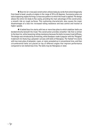
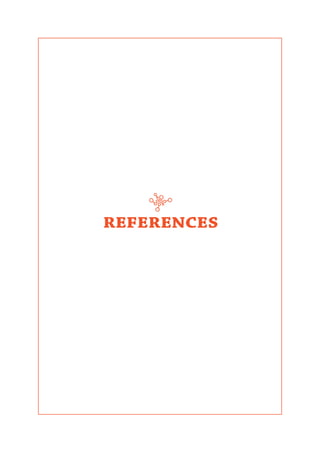
![144
1. Authority, T.R., Rubber authority annual report 2019. 2019, Annual report 2019, Bangkok,
Thailand: Thailand Rubber Authority.
2. Admin. 5 World’s largest natural rubber producer in 2019. 2019 [cited 2022 10 April 2022];
Availablefrom:https://scienceagri.com/5-worlds-largest-natural-rubber-producers-in-2019/.
3. Choosong,T.,etal.,Workingenvironmentinarubbersheetsmokingfactorypollutedbysmoke
from biomass fuel burning and health influences to workers. Journal of Ecotechnology
Research, 2007. 13(2): p. 91-96.
4. Tassanakul, P., Preparation of air dried sheet in current situation 2015, Rubber authority
of thailand: Para rubber electronic bulletin. p. 14.
5. Tassanakul, P., ; Wichern, Adul,; Pimrat, Pisit, TMTD/ZnO free preservative system for
concentrated latex 2016, Rubber authority of thailand: Para Rubber Electronic Bulletin. p. 10.
6. Tanaka, Y., S. Kawahara, and J. Tangpakdee, Structural characterization of natural rubber.
Kautschuk Gummi Kunststoffe, 1997. 50(1): p. 6-11.
7. Yunyongwattanakorn, J. and J.T. Sakdapipanich, Physical property changes in commercial
natural rubbers during long term storage. Rubber chemistry and technology, 2006. 79(1):
p. 72-81.
8. Pike, M. and W. Watson, Mastication of rubber, I. Mechanism of plasticizing by cold
mastication. Journal of Polymer Science, 1952. 9(3): p. 229-251.
9. Takahashi, S. and T. Koyama, Structure and function of cis-prenyl chain elongating
enzymes. The Chemical Record, 2006. 6(4): p. 194-205.
10. Kadir, A.A.S., Advances in natural rubber production. Rubber chemistry and technology,
1994. 67(3): p. 537-548.
11. Eng, A.-H. and Y. Tanaka, Structure of natural rubber. Trends in Polymer Science, 1993.
3: p. 493-513.
12. Tanaka, Y., Structural characterization of natural polyisoprenes: solve the mystery of
natural rubber based on structural study. Rubber chemistry and technology, 2001. 74(3):
p. 355-375.
13. Kent, J.A., Kent and Riegel’s handbook of industrial chemistry and biotechnology. 2007.
14. Gent, A., S. Kawahara, and J. Zhao, Crystallization and strength of natural rubber and
synthetic cis-1, 4-polyisoprene. Rubber Chemistry and technology, 1998. 71(4): p. 668-678.
15. Huneau, B., Strain-induced crystallization of natural rubber: a review of X-ray diffraction
investigations. Rubber chemistry and technology, 2011. 84(3): p. 425-452.
Chapter 1
REFERENCES](https://image.slidesharecdn.com/worldofrubber-2022-dr-220920074909-7d531796/85/World-Of-Rubber-146-320.jpg)
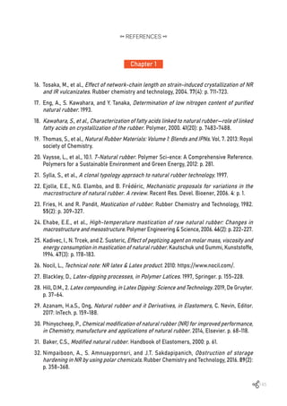
![146
33. National Bureau of Agricultural Commodity and Food Standards, M.o.A.a.C., Good
manufacturing practices for ribbed smoked sheet, in Thai Agricultural Standard. 2013:
Royal Thai Government Gazette.
34. National Bureau of Agricultural Commodity and Food Standards, M.o.A.a.C., Good
manufacturing practices for crepe rubber in Thai Agricultural Standard. 2018: Royal Thai
Government Gazette.
35. National Bureau of Agricultural Commodity and Food Standards, M.o.A.a.C., Good
agricultural practices for para rubber part 1: field latex production, in Thai Agricultural
Standard. 2019: Royal Thai Government Gazette.
36. National Bureau of Agricultural Commodity and Food Standards, M.o.A.a.C., Good
agricultural practices for para rubber part 2: cup lump production, in Thai Agricultural
Standard. 2020: Royal Thai Government Gazette.
37. National Bureau of Agricultural Commodity and Food Standards, M.o.A.a.C., Good
manufacturing practices for field latex collecting center, in Thai Agricultural Standard.
2021: Royal Thai Government Gazette.
38. Sowcharoensuk, C. Industry Outlook 2021-2023: Natural Rubber Processing. 2021 [cited
2021 21/4/2021]; Available from: https://www.krungsri.com/en/research/industry/
industry-outlook/agriculture/rubber/IO/io-rubber-21.
39. Rubber, G.P.f.S.N. GPSNR POLICY FRAMEWORK. 2022 [cited 2022; Available from: https://
sustainablenaturalrubber.org/policy-framework/.
40. Rubber, G.P.f.S.N. About GPSNR. 2022 [cited 2022; Available from: https://sustainable-
naturalrubber.org/about-us/.
41. Council®, F.S., FSC Principles and Criteria for Forest Stewardship. 2015: FSC Principles
and Criteria for Forest Stewardship.
42. Council®, F.S., Chain of Custody Certification. 2021: fsc.org.
43. Brown, W. The History of Disposable Gloves. 2016 [cited 2016 12/12/2016]; Available from:
https://blog.ammex.com/the-history-of-disposable-gloves/#.
44. Kanjanavisut, K. COVID-19 increased global demand for medical glove. EIC indicates that
Malaysia gains more from export than Thailand. 2020 [cited 2020 1/6/2020].
45. Bangkok Synthetics Co., L., Rubber glove demand. 2021: Bangkok Synthetics Co., Ltd.
46. Association, M.R.G.M., Malaysian Rubber Glove Industry – Impact of COVID-19. 2020:
Companies data, Televisory research.
Chapter 1
REFERENCES](https://image.slidesharecdn.com/worldofrubber-2022-dr-220920074909-7d531796/85/World-Of-Rubber-148-320.jpg)
![147
47. Nation,T.Thailandnowsecond-biggestrubberglovesexporteramidCovid-19pandemic.2020
[cited 2020 5/12/2020]; Available from: https://www.nationthailand.com/business/30399152.
48. Bangkok Synthetics Co., L., Market demand and trend – by Segmentation t.a. Expert
interview, Editor. 2020: Bangkok Synthetics Co., Ltd.
49. Yip, E. and P. Cacioli, The manufacture of gloves from natural rubber latex. Journal of
allergy and clinical immunology, 2002. 110(2): p. S3-S14.
50. Jirasukprasert, P., et al. A case study of defects reduction in a rubber gloves manufacturing
process by applying Six Sigma principles and DMAIC problem solving methodology. in
Proceedings of the 2012 international conference on industrial engineering and operations
management. 2012.
51. Wattana, T.a.L., Suphatchakorn Medical latex glove. 2011. 38, 67-72.
52. Br MSME, D.I. Project profile on rubber hand glove manufacturing unit. 2020 [cited 2020
6/6/2020]; Available from: http://www.msmedi-guwahati.gov.in/PDF/Project_profile_on_
Rubber_Hand_Glove.pdf.
53. Akabane, T., Production method & market trend of rubber gloves. International Polymer
Science and Technology, 2016. 43(5): p. 45-50.
54. Taylor, M. These biodegradable gloves provide a green alternative to synthetic rubber.
2020 [cited 2020 30/11/2020]; Available from: https://www.weforum.org/agenda/2020/11/
covid-19-prompts-pivot-to-green-alternative-to-rubber-gloves/.
55. Misman, M.A. and A.R. Azura. Overview on the potential of biodegradable natural Rubber
Latex gloves for commercialization. in Advanced Materials Research. 2014. Trans Tech Publ.
Chapter 1
REFERENCES](https://image.slidesharecdn.com/worldofrubber-2022-dr-220920074909-7d531796/85/World-Of-Rubber-149-320.jpg)
![148
Chapter 2
REFERENCES
1. Glenn, F.E., Chapter: Chloroprene Polymers. Encyclopedia of Polymer Science and
Technology. John Wiley & Sons, Inc, 2002.
2. Sisanth, K., et al., General introduction to rubber compounding, in Progress in rubber
nanocomposites. 2017, Elsevier. p. 1-39.
3. Lynch, M., Manufacture and use of chloroprene monomer. Chemico-Biological Interactions,
2001. 135: p. 155-167.
4. Johnson, P.R., Polychloroprene rubber. Rubber Chemistry and Technology, 1976. 49(3):
p. 650-702.
5. DuPont. DuPont™ Neoprene Dry Grades Selection Guide for Adhesive Applications. 2010
[cited 2010; Available from: http://www.chemwinfo.com/private_folder/Uploadfile-
2014December/Dupont_Neoprene_-_Dry_Grades_Select.pdf.
6. DuPont. DuPont™ Neoprene Dry Grades Selection Guide for Adhesive Applications. 2010
[cited 2022 25/4/2022]; Available from: http://www.chemwinfo.com/private_folder/
Uploadfile2014December/Dupont_Neoprene_-_Dry_Grades_Select.pdf.
7. Graves, D., Rubber, in Handbook of Industrial Chemistry and Biotechnology. 2012, Springer.
p. 621-642.
8. Elastomer,D.P.NeoprenepolychloropreneAGuidetoGrades,CompoundingandProcessingof
NeopreneRubber2008[cited2008;Availablefrom:http://www.chemwinfo.com/private_folder/
Uploadfile2014December/DUPONT_neoprene_A_Guide_to_Grades,_.pdf.
9. Hofmann, W., Vulcanization and vulcanizing agents. 1967: Maclaren London.
10. Coran, A.Y., Vulcanization, in Science and technology of rubber. 1994, Elsevier. p. 339-385.
11. The Kempermann, S.K., J. Summer, Manual for the rubber industry. Synthetic rubber. 1993,
Leverkusen, Germany: Bayer AG.
12. Elastomers, A.P., About Arlanxeo. 2019.
13. Valley, T.C. Technical Data Sheet Ricon® 100 / Ricon® 100 KC. 2020 [cited 2020 21/5/2020];
Available from: https://www.crayvalley.com/docs/default-source/tds/ricon-100_100kc_
cr-bm-li-601_052020204e90ccf91a3467be9c31ff0000465d97.pdf?sfvrsn=aba4abd0_2.
14. McKeen, L., 10-Elastomers and Rubbers. Permeability Properties of Plastics and Elastomers
(Fourth Edition), William Andrew Publishing, 2017: p. 209-247.
15. Hamed, G.R., Materials and compounds. Engeneering with rubber, how to design rubber
components, 1992: p. 21.](https://image.slidesharecdn.com/worldofrubber-2022-dr-220920074909-7d531796/85/World-Of-Rubber-150-320.jpg)
![149
16. Milner, P., Advances in Nitrile Rubber (NBR), in Developments in Rubber Technology—4.
1987, Springer. p. 57-85.
17. Bertram, H., Developments in Acrylonitrile—Butadiene Rubber (NBR) and Future
Prospects, in Developments in Rubber Technology—2. 1981, Springer. p. 51-85.
18. Pal, K., et al., Effect of fillers on morphological properties and wear characteristics of
XNBR/NR blends. Journal of Applied Polymer Science, 2011. 120(2): p. 710-718.
19. Aliabadi, M.M., et al., Mechanical and barrier properties of XNBR-clay nanocomposite: a
promising material for protective gloves. Iranian Polymer Journal, 2014. 23(4): p. 289-296.
20. Meyer, G., R. Kavchok, and F. Naples, Emulsion Rubbers Copolymerized with Monomeric
Antioxidants. Rubber Chemistry and Technology, 1973. 46(1): p. 106-114.
21. Sulekha, P. and R. Joseph, Studies on polymer bound antioxidants in NBR vulcanizates.
International Journal of Polymeric Materials, 2005. 54(5): p. 333-345.
22. Wang, H., L. Yang, and G.L. Rempel, Homogeneous hydrogenation art of nitrile butadiene
rubber: a review. Polymer Reviews, 2013. 53(2): p. 192-239.
23. Keller, R., Practical Guide to Hydrogenated Nitrile Butadiene Rubber Technology. 2012:
Smithers Rapra.
24. Singha, N., S. Bhattacharjee, and S. Sivaram, Hydrogenation of diene elastomers, their
properties and applications: a critical review. Rubber chemistry and technology, 1997.
70(3): p. 309-367.
25. Hayashi, S., Nitrile and hydrogenated nitrile rubber, in Handbook of Elastomers. 2000,
CRC Press. p. 803-834.
26. Grosch, K. and P.M.L. Swift, Oil extended natural rubber for tire treads. Rubber Chemistry
and Technology, 1966. 39(5): p. 1656-1666.
27. Herbert, C.G., L.R.D.A. Lima, and C. Gonçalves, Alternative to Phthalate Plasticizer for PVC/
NBR Formulation Used in Automotive Fuel System with Biodiesel. 2017, SAE Technical
Paper.
28. Cadogan, D.F. and C.J. Howick, Plasticizers. Ullmann’s encyclopedia of industrial
chemistry, 2000.
29. Thakur, V., et al., Sponge EPDM by design. Plastics, Rubber and Composites, 2019. 48(1):
p. 32-41.
30. Dow, C. NORDEL™ EPDM Product Selection Guide. 2021 [cited 2021 10/05/2021]; Available
from: https://www.dow.com/documents/en-us/catalog-selguide/265/265-11001-01-nordel-
epdm-product-selection-guide.pdf.
Chapter 2
REFERENCES](https://image.slidesharecdn.com/worldofrubber-2022-dr-220920074909-7d531796/85/World-Of-Rubber-151-320.jpg)
![150
31. Starmer, P.H. and F.R. Wolf, Acrylic elastomers, survey. Encyclopedia of polymer science
and technology, 2002.
32. Baranwal, K.C. and H.L. Stephens, Basic elastomer technology. 2001: Rubber Division.
33. Tao, Z., et al., Heat resistant elastomers. Rubber chemistry and technology, 2005. 78(3):
p. 489-515.
34. DuPont™. Vamac® Grade Selection. 2022 [cited 2022 2/3/2022]; Available from: https://
www.dupont.com/knowledge/vamac-grade-performance.html#:~:text=Vamac%C2%AE%20
is%20generally%20assigned,raing%20of%20EG%20or%20EF.&text=For%20reduced%20
oil%20swell%2C%20DuPont,)%20in%20low%2Dtemperature%20flexibility.
35. Stephen, L. Polymers and plastics. 2017 [cited 2017 23/10/2017]; Available from: https://
www.chem1.com/acad/webtext/states/polymers.html.
36. Shit, S.C. and P. Shah, A review on silicone rubber. National academy science letters,
2013. 36(4): p. 355-365.
37. Kaliyathan,A.V.,etal.,Naturalrubberandsiliconerubber-basedbiomaterials,inFundamental
Biomaterials: Polymers. 2018, Elsevier. p. 71-84.
38. Lorenz, G. and A. Kandelbauer, Silicones, in Handbook of Thermoset Plastics. 2014, Elsevier.
p. 555-575.
39. Polmanteer, K.E., Silicone rubber, its development and technological progress. Rubber
chemistry and technology, 1988. 61(3): p. 470-502.
40. Kipping, F. and L. Lloyd. Organische siliciumhaltige Verbindungen. in Proc. Chem. Soc. 1899.
41. Mahmood, S., et al. A review on the cords & plies reinforcement of elastomeric polymer
matrix. in IOP Conference Series: Earth and Environmental Science. 2016. IOP Publishing.
42. Heiner, J., B. Stenberg, and M. Persson, Crosslinking of siloxane elastomers. Polymer
testing, 2003. 22(3): p. 253-257.
43. LeFan, J. and M. Eng, Liquid silicone rubber injection molding. Saint-Gobain Performance
Plastics. Available at: http://www. medical. saint-gobain. com/sites/default/files/LSR-
White-Paper_5-9-11_Jeff-Lefan. pdf% 5Cnwww. medical. saint-gobain. com, 2011.
44. Dluzneski, P.R., Peroxide vulcanization of elastomers. Rubber chemistry and technology,
2001. 74(3): p. 451-492.
45. Witt, N., et al., Silicone rubber nanocomposites containing a small amount of hybrid fillers
with enhanced electrical sensitivity. Materials & Design, 2013. 45: p. 548-554.
Chapter 2
REFERENCES](https://image.slidesharecdn.com/worldofrubber-2022-dr-220920074909-7d531796/85/World-Of-Rubber-152-320.jpg)
![151
46. Wen, J., et al., Preparation and characterization of nano-hydroxyapatite/silicone rubber
composite. Materials Letters, 2008. 62(19): p. 3307-3309.
47. Ushmarin, N., et al., The influence of stabilizers on the properties of silicone rubber.
Polymer Science, Series D, 2017. 10(4): p. 305-308.
48. Hamdani, S., et al., Flame retardancy of silicone-based materials. Polymer Degradation
and Stability, 2009. 94(4): p. 465-495.
49. Spencer, W., et al., Compounding of silicone rubber. Industrial & Engineering Chemistry,
1953. 45(6): p. 1297-1304.
50. Ferrandez, P., Fluoroelastomers, FKM and FEPM. Handbook of Specialty Elastomers, ed.
CK Robert, editor., Taylor & Francis Group, New York, 2008: p. 133-154.
51. Schroeder, H., Fluorocarbon elastomers, in Rubber Technology. 1987, Springer. p. 410-437.
52. Valentini, L. and M.A. Lopez-Manchado, Classification of rubbers and components for
harsh environmental systems, in High-Performance Elastomeric Materials Reinforced
by Nano-Carbons. 2020, Elsevier. p. 1-14.
53. Drobny, J.G., Technology of fluoropolymers. 2008: CRC Press.
54. Drobny, J.G. and A.L. Moore, Fluoroelastomers handbook: the definitive user’s guide and
databook. 2006: Taylor & Francis.
55. Dakin Industries, L. Fluoroelastomers. 2022; Available from: https://www.daikinchemicals.
com/solutions/products/dai-el-fluoroelastomers.html.
56. Drobny, J.G., Chapter10-Fluoroelastomers, in IntroductiontoFluoropolymers, S. Ebnesajjad,
Editor. 2013, William Andrew Publishing: Oxford. p. 149-230.
57. Elastomers, D.P., Perfluoroelastomer and Fluoroelastomer Seals for Photovoltaic Cell
Manufacturing Processes. Intersol. SMET May, 2009.
58. Ogunniyi, D., A novel system for crosslinking fluoroelastomers. Rubber chemistry and
technology, 1988. 61(5): p. 735-746.
59. Fuller, R.E., Fluoroelastomers made with advanced polymer architecture for oil and gas
applications. Oilfield Engineering with Polymers, 2006: p. 29-30.
60. Logothetis, A.L., Chemistry of fluorocarbon elastomers. Progress in polymer science,
1989. 14(2): p. 251-296.
61. Chemours,C.Viton™fluoroelastomersOvenPost-CuringofParts.2020[cited202017/9/2020];
Available from: https://www.chemours.cn/-/media/files/viton/viton-post-curing.pdf.
Chapter 2
REFERENCES](https://image.slidesharecdn.com/worldofrubber-2022-dr-220920074909-7d531796/85/World-Of-Rubber-153-320.jpg)
![152
62. DuPont Dow, E. Viton® Selection Guide. 2009 [cited 2009 9/9/2008]; Available from: https://
rainierrubber.com/wp-content/uploads/2014/01/Viton-Selection-Guide.pdf.
63. Chemours, C. Viton™ Dipolymers A-Type Fluoroelastomer. 2022 [cited 2022; Available
from: https://www.viton.com/en/products/a-type#:~:text=The%20Viton%E2%84%A2%20
A%2Dtype,chemicals%20and%20metal%20adhesion%20promoters.
64. DuPont Dow, E. The Viton® A-Type Fluoroelastomers Technical Information. 2000; Available
from: http://www.chemourscg.com/nbfile/activitytempfile/160808/1608080109304220.pdf.
65. ChemoursCompanyFC,L.V.Viton™fluoroelastomerSelectionGuide.2017[cited20173/6/2017];
Available from: https://www.viton.com/en/-/media/files/viton/viton-selection-guide.pdf?
rev=4d820d8dba554da98e6f896791b3c1a9&hash=AC986224DEA6E9FCC4BBFD5D2B4BAE9C.
66. Chemours, C. Viton™ fluoroelastomers-Processing Guide. 2017 [cited 2017 28/2/2017];
Available from: https://www.chemours.cn/-/media/files/viton/viton-processing-guide.pdf.
67. Bhattacharya, A.B., T. Chatterjee, and K. Naskar, Automotive applications of thermoplastic
vulcanizates. Journal of Applied Polymer Science, 2020. 137(27): p. 49181.
68. Van Duin, M. Crosslinking systems for EPDM/PP-based thermoplastic vulcanizates. in
International Rubber Conference, Birmingham, England. 2001.
Chapter 2
REFERENCES](https://image.slidesharecdn.com/worldofrubber-2022-dr-220920074909-7d531796/85/World-Of-Rubber-154-320.jpg)
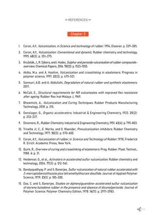
![154
Chapter 3
REFERENCES
16. Manik, S. and S. Banerjee, Effect of sulfur and dicumyl peroxide on vulcanization of natural
rubber with tetramethylthiuram disulfide and zinc oxide. Rubber Chemistry and Technology,
1970. 43(6): p. 1294-1310.
17. Nocil, L. Vulcanization & Accelerators. 2012 [cited 2010 22/10/2012]; Available from: https://
www.nocil.com/Downloadfile/DTechnicalNote-Vulcanization-Dec10.pdf.
18. Coleman, M.M., J.R. Shelton, and J.L. Koenig, Sulfur vulcanization of hydrocarbon diene
elastomers. Industrial & Engineering Chemistry Product Research and Development,
1974. 13(3): p. 154-166.
19. Indrajati, I.N. and I.R. Dewi, Performance of binary accelarator system on natural rubber
compound. Majalah Kulit, Karet, dan Plastik, 2019. 34(2): p. 49-60.
20. Campbell, R. and R. Wise, Vulcanization. Part II. Fate of curing system during sulfur curing
of NR accelerated by MBT derivatives and activated by zinc stearate. Rubber Chemistry
and Technology, 1964. 37(3): p. 650-667.
21. Ostromislensky, I., A process for making butadiene by condensing ethanol with
acetaldehyde over an oxide catalyst at 360 to 440 C. Journal of Russian Physical and
Chemical Society, 1915. 47: p. 1885.
22. Henning, S.K., Use of coagents in the radical cure of elastomers. Wire & Cable Technology
International XXXVI, 2008, 2008: p. 52-59.
23. Li, Y., Effect of Crosslink Density on the Tearing of Gum Natural Rubber Cured with Dicumyl
Peroxide (DCP). 2013, University of Akron.
24. Dluzneski, P.R.,FEATURES-Thechemistryofperoxidevulcanization-Productsareformulated
using peroxide curatives. Rubber World, 2001. 224(5): p. 34-37.
25. Grima, M.M.A., Novel co-agents for improved properties in peroxide cure of saturated
elastomers. 2007.
26. Visakh, P., et al., Advances in elastomers II. Springer, Berlin. doi, 2013. 10: p. 978-3.
27. Henning, S.K. and R. Costin. Fundamentals of curing elastomers with peroxides and
coagents I: Coagent structure-property relationships. in 167th
Technical Meeting of the
Rubber Division, American Chemical Society. 2005.
28. Dluzneski, P.R., Peroxide vulcanization of elastomers. Rubber chemistry and technology,
2001. 74(3): p. 451-492.
29. Class, J.B., A review of the fundamentals of crosslinking with peroxides. Rubber world,
1999. 220(5): p. 35-39.](https://image.slidesharecdn.com/worldofrubber-2022-dr-220920074909-7d531796/85/World-Of-Rubber-156-320.jpg)
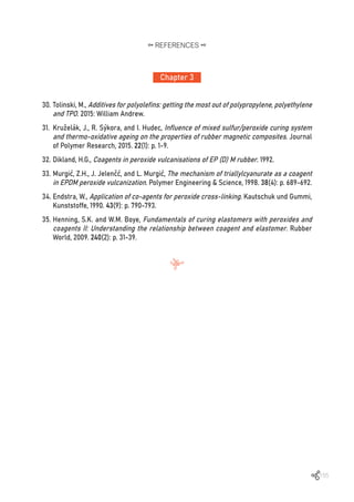
![156
Chapter 4
REFERENCES
1. Stahl, W.M., Choosing the right elastomer for the right application. World Pumps, 2006.
2006(481): p. 30-33.
2. Gijsman, P., J. Hennekens, and D. Tummers, The mechanism of action of hindered amine
light stabilizers. Polymer degradation and stability, 1993. 39(2): p. 225-233.
3. Pospíšil, J., Chemical and photochemical behaviour of phenolic antioxidants in polymer
stabilization: a state of the art report, part II. Polymer degradation and stability, 1993.
39(1): p. 103-115.
4. Cheremisinoff, N.P., Condensed encyclopedia of polymer engineering terms. 2001:
Butterworth-Heinemann.
5. Meurant, G., Atmospheric Oxidation and Antioxidants, Volume 2, G. Scott, Editor. 2012:
Elsevier Science Publishers B.V.
6. Bailey, P.S., The reactions of ozone with organic compounds. Chemical Reviews, 1958.
58(5): p. 925-1010.
7. Hamed, G.R., Materials and compounds. Engeneering with rubber, how to design rubber
components, 1992: p. 21.
8. Machine, C. The Difference Between Tangential and Intermeshing Dispersion Kneader
Machines. 2019 [cited 2019 28/10/2019]; Available from: https://cncmachineinchina.
blogspot.com/2019/10/the-difference-between-tangential-and.html.
9. Sapkota,J.,Influenceofclaymodificationoncuringkineticsofnaturalrubbernanocomposites.
2011.
10. HF Rubber Machinery, I. Mixers. 2011 [cited 2011 9/4/2011]; Available from: http://www.
hfrmusa.com/static_main.php?site=mixers.
11. Pomini, F. Banbury mixer. 2022 [cited 2022; Available from: www.farrel.com.
12. Britannica, E., Banbury mixer, B. mixer, Editor. 2022: Encyclopædia Britannica.
13. Chareon tut, C.L. CT Two Roll Mill. 2022 [cited 2021 20/4/2021]; Available from:
https://www.chareontut.com/Two-Roll_Und_Mill/60a4e1c6081e540013e2d3c9.](https://image.slidesharecdn.com/worldofrubber-2022-dr-220920074909-7d531796/85/World-Of-Rubber-158-320.jpg)
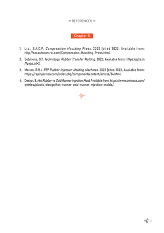
![158
Chapter 6
REFERENCES
1. Bower, M.E.A.E.W., Manufacturer of rubber goods, in Google Patents. 1933, Dunlop Rubber
Co. Ltd.
2. Wikipedia. Foam rubber. 2022 12/6/2022 [cited 2022 12/6/2022]; Available from:
https://en.wikipedia.org/wiki/Foam_rubber#cite_note-Patent-3.
3. Price, C.C., Polyether polyurethane rubber, in United States Patents. 1958, University of
Notre Dame.
4. Ariff, Z., et al., Effect of foaming temperature and rubber grades on properties of natural
rubber foams. Journal of applied polymer science, 2008. 107(4): p. 2531-2538.
5. Jorge Alejandro Kabbabe Malave, J.-P.P., Camille Louise Adrienne DUPONT, Functionalized
particulate bicarbonate as blowing agent, foamable polymer composition containing it, and
its use in manufacturing a thermoplastic foamed polymer, in World Intellectual Property
Organization. 2019.
6. Guan, L., et al., Foaming and chain extension of completely biodegradable poly (propylene
carbonate) using DPT as blowing agent. Journal of Polymer Research, 2007. 14(3): p. 245-251.
7. Wikipedia. Azodicarbonamide. 2022 12/3/2022 [cited 2022 12/3/2022]; Available from:
https://en.wikipedia.org/wiki/Azodicarbonamide.
8. Drobny, J.G., Handbook of thermoplastic elastomers. 2014: Elsevier.
9. Coste, G., C. Negrell, and S. Caillol, From gas release to foam synthesis, the second breath
of blowing agents. European Polymer Journal, 2020. 140: p. 110029.
10. Guide, S. Anatomy of the Shoe: Shoe Terminology. 2020 [cited 2020 7/6/2020]; Available
from: https://www.shoeguide.org/shoe_anatomy/.
11. Wikipedia. Ethylene-vinyl acetate. 2022 [cited 2022 29/6/2022]; Available from:
https://en.wikipedia.org/wiki/Ethylene-vinyl_acetate#cite_note-5.
12. Stridewise. What Is EVA Foam and Why Is It Being Put In Boots? ; Available from:
https://stridewise.com/what-is-eva-foam/.
13. Jenkins, M., Materials in sports equipment. Vol. 1. 2003, Woodhead Publishing Ltd and CRC
Press LLC: Cambridge: Woodhead Publishing.](https://image.slidesharecdn.com/worldofrubber-2022-dr-220920074909-7d531796/85/World-Of-Rubber-160-320.jpg)
![159
Chapter 7
REFERENCES
1. Publishing, D., DK Eyewitness Books: Transportation: Discover the Fascinating World of
Transportation, from Ancient Carts to Modern High-Speed Trains. 2012, DK Eyewitness
Books.
2. Ikeda, Y., et al., Pneumatic Tire Technology, in Rubber Science. 2018, Springer. p. 155-191.
3. Tompkins, E., The history of the pneumatic tyre. 1981: Eastland Press.
4. Wikipedia. BenzPatent-Motorwagen. 2022 11/7/2022; Available from: https://en.wikipedia.org/
wiki/Benz_Patent-Motorwagen.
5. Wikipedia. Tire. 2022 [cited 2022 5/6/2022]; Available from: https://en.wikipedia.org/wiki/
Tire#cite_note-24.
6. Zippia, I. GOODYEAR HISTORY. 2022; Available from: https://www.zippia.com/the-goodyear-
tire-rubber-careers-11458/history/.
7. Michelin. 130 years of Michelin innovation. 2022 [cited 2022; Available from: https://www.
michelin.com/en/innovation/research-and-development/130-years-of-michelin-innovation/.
8. Group, J.A. A HISTORICAL BACKGROUND. 2001 [cited 2001 1/5/2001]; Available from:
http://www.jags.org/TechInfo/2001/05May01/tires/historyoftires.htm.
9. Duffy, O.C. and G. Wright, Fundamentals of Medium/Heavy Duty Commercial Vehicle Systems:
2014 NATEF Edition. 2015: Jones & Bartlett Publishers.
10. Newton, R., Wheel and Tire Performance Handbook. 2007: MotorBooks International.
11. Allen, J. and J. Weber, Jeep 4x4 Performance Handbook. 2021: Motorbooks International.
12. Hanseen, M., Jeep TJ 1997-2006: How to Build & Modify, B. Wilson, Editor. 2018, CarTech Inc.
13. Terrill, E., et al., Dynamic mechanical properties of passenger and light truck tire treads.
Report No. DOT HS, 2010. 811(270): p. 28.
14. Alexander, D., High-PerformanceHandlingforStreetorTrack:Vehicledynamics, suspension
mods & setup-Anti-roll bars, camber adjusters & chassis braces-High-performance
driving techniques. 2011: Motorbooks.
15. Gitlin, J.M. Electric vehicles ask a lot of their tires—here’s why. 2021; Available from:
https://arstechnica.com/cars/2021/12/why-electric-vehicle-tires-are-challenging-to-make/.
16. Erjavec, J., Automotive Technology: a Systems Approach, vol. 2. Thomson Delmar Learning.
Clifton Park, NY, 2005: p. 845.
17. Haines, E., CertainOff-the-RoadTiresfromChina. 2008, U.S. International Trade Commission:
U.S. International Trade Commission.](https://image.slidesharecdn.com/worldofrubber-2022-dr-220920074909-7d531796/85/World-Of-Rubber-161-320.jpg)
![160
Chapter 7
REFERENCES
18. Currey, N.S., Aircraft landing gear design: principles and practices. 1988: Aiaa.
19. Richfield, P.J., Tundra Tire Nation: Big Rubber and the Lure of the Bush Pilot Mystique.
2005, FLYING. p. 88-92.
20. Zhang, Z.Z., et al. Development of non-pneumatic tire technology. in Applied Mechanics
and Materials. 2013. Trans Tech Publ.
21. Rhyne, T.B. and S.M. Cron, Development of a non-pneumatic wheel. Tire Science and
Technology, 2006. 34(3): p. 150-169.
22. Sharp, A., Bicycles & tricycles: an elementary treatise on their design and construction,
with examples and tables. 1896: Longmans, Green.
23. Rinard, D. Tire Bead Test. 2022 07/11/2022 [cited 2001; Available from: https://www.
sheldonbrown.com/rinard/tirebead.htm.
24. Rodgers, B. and W. Waddell, Tire engineering, in Science and technology of rubber. 2005,
Elsevier. p. 619-II.
25. VanGelder, K., Fundamentals of automotive technology: principles and practice. 2017:
Jones & Bartlett Learning.
26. Kumar, A. TYRE. 2019 [cited 2019 14/2/2019]; Available from: https://www.dpgpolytechnic.
com/downloads/files/n5d68b351417ef.pdf.
27. Gupta, S., A Textbook of Automobile Engineering. 2020: S. Chand Publishing.
28. Cheah, H., et al. Design and Development of the Mechanism for Run Flat Tyre, Part 3. in
2nd Integrated Design Project Conference (IDPC). 2015.
29. Gent, A.N. and J.D. Walter, Pneumatic tire. 2006.](https://image.slidesharecdn.com/worldofrubber-2022-dr-220920074909-7d531796/85/World-Of-Rubber-162-320.jpg)
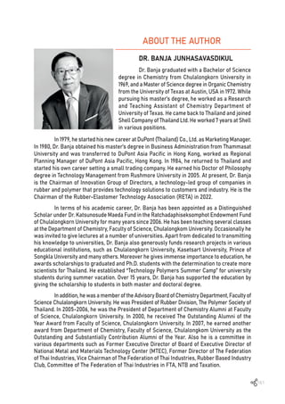
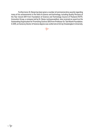


The document discusses elastomeric materials, particularly focusing on natural and synthetic rubber, their properties, and their importance in various applications. It outlines the history of rubber, including the discovery of vulcanization and its impact on industrial development, as well as the modern advancements in rubber technology and production. The text serves as an educational resource for industry professionals and researchers, covering the technical aspects of rubber processing and applications.