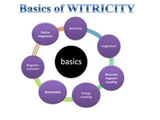
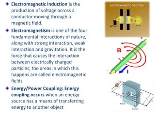
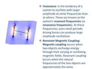
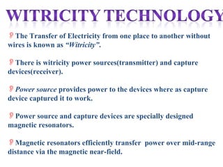
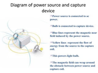
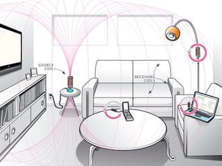
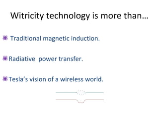
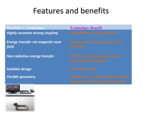
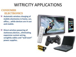
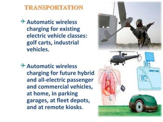
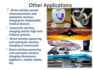
--The Wireless Electricity.


      By
Karan Bir Singh
   E073026
What is witricity?
Witricity is nothing but wireless electricity.
Transmission of electrical energy from one
 object to another without the use of wires is
 called as Witricity.
Because of Witricity some of the devices
 won't require batteries to operate.
The story started late one night a
    few years ago. It was probably
    the sixth time that month that
.
    MIT Professor Marin Soljacic
    was awakened by his mobile
    phone beeping battery low. At
    that time it occurred to him that
    there is electricity wired all
    through his house, office-
    everywhere. He think about- how
    it is possible to use electricity
    without using wires…
Electro
magnetism


                Resonant
                magnetic
                coupling


    RESONANCE
Electromagnetic induction is the
production of voltage across a
conductor moving through a
magnetic field.
Electromagnetism is one of the four
fundamental interactions of nature,
along with strong interaction, weak
interaction and gravitation. It is the
force that causes the interaction
between electrically charged
particles; the areas in which this
happens are called electromagnetic
fields
Energy/Power Coupling: Energy
coupling occurs when an energy
source has a means of transferring
energy to another object
Resonance :is the tendency of a
system to oscillate with larger
amplitude at some frequencies than
at others. These are known as the
system's resonant frequencies (or
resonance frequencies). At these
frequencies, even small periodic
driving forces can produce large
amplitude oscillations
Resonant Magnetic Coupling:
Magnetic coupling occurs when
two objects exchange energy
through their varying or oscillating
magnetic fields. Resonant coupling
occurs when the natural
frequencies of the two objects are
approximately the same.
The Transfer of Electricity from one place to another without
wires is known as “Witricity”.

There is witricity power sources(transmitter) and capture
devices(receiver).

Power source provides power to the devices where as capture
device captured it to work.

Power source and capture devices are specially designed
magnetic resonators.

Magnetic resonators efficiently transfer power over mid-range
distance via the magnetic near-field.
Near field
 Near field is a wireless transmission
  technique over distances comparable to or a
  few times the diameter of devices.

 Near field is usually magnetic.

 Near field energy is non radiative .but some
  radiative and resistive losses will occur.
Coupled resonators
 Two resonant objects of the same resonant
  frequency tend to exchange energy.

 It exchange energy strongly ,while interacting
  weakly with living beings and other
  environmental objects.

 Coupled resonators are said to be operate in
  strongly coupled regime to avoid material
  absorption and radiative loss.
MIT teams behind witricity technology
The first experiment of witricity, the concept of wireless
electricity, was conducted in the year 2006, by researchers
from Massachusetts Institute of Technology. The Assistant
Professor of this team of researchers was Marin Soljacic.


2007: A physics
research group, led by
Prof. Marin Soljacic,at MIT,
wirelessly power a 60W
light bulb with 40%
efficiency at a 2 meters
(6.6 ft) distance using two
60 cm-diameter coils
Schematic Diagram
Diagram of power source and capture
              device
                  Power source is connected to ac
                  power.

                  Bulb is connected to capture device.

                  Blue lines represent the magnetic near
                  field induced by the power source.

                  Yellow lines represent the flow of
                  energy from the source to the capture
                  coil.

                  This powers light bulb.

                  The magnetic field can wrap around
                  the obstacle between power source and
                  capture coil.
Range & Rate of Coupling:


          Using Coupled Mode Theory (CMT), we can give some frame work
to the system. The field system of the two resonant objects 1, 2 is
                          F(r,t)=a1(t)F1(r)+a2(t)F2(r)
Where F1,2(r) are the resonating modes of 1 and 2 alone, and then the field
amplitudes a1(t) and a2(t).The lower order representation of the system is
given by :


Where ω1, 2 are the individual frequencies, Γ1, 2 are the Resonance widths
(Decay rates) due to the objects’ intrinsic (absorption, radiation etc.) losses,
and ‘κ’ is the coupling coefficient .
The solution of the equation show that at exact resonance at
                      ω1=ω2 and Γ1=Γ2
the normal modes of the combined system are split by 2κ.
Ratio {κ /sqrt (Γ1, 2)} shows that, it will set as figure-of-
merit for any system under consideration for wireless energy-
transfer, along with the distance over which this ratio can be
achieved.
 The desired optimal regime {κ/sqrt (Γ1,2)>>1} is called
“Strong-Coupling” regime. There is No change in Energy,
unless κ/Γ>>1 is true.
Simulation model Using COMSOL:


Simulation Performance:
 By the basic parameters, calculated results and performance
given with and Without the External object in between the coils.
Comparison of Results:
Results without Extraneous objects:
Two loops           D/r   Qrad     Q=ω/2Γ ω/2κ      κ/ Γ
R=30cm,a=2mm,       3     30729    4216     63.7    68.7
ε=10,               5     29577    4194     248     17.8
d=4mm,Qabs=4886.

Results with Extraneous objects:

Two loops           D/r   Qrad     Q=ω/2Γ    ω/2κ    κ/ Γ
R=30cm,a=2mm,       3     30729    4136      62.6    67.4
ε=49+16i,
                    5     29577    4106      235     17.6
d=4mm,Qabs=4886.
Witricity technology is more than…

 Traditional magnetic induction.

Radiative power transfer.

Tesla’s vision of a wireless world.
Used in power transformers.
 conductive coils transmit power to each
 other wirelessly, over very short distance.
  An electric tooth brush uses
  traditional magnetic induction to
  recharge its batteries
Radio frequency energy is used for wireless
 power transfer.
Radiated power is wasted into free space
Need line of sight.
Harmful.

                            Microwave oven utilizes
                            radiation to cook foods
Nikola Tesla the most well known scientist
had a vision of wireless world.

In which wireless electric power and
communication would reach around the world,
delivering information and power.


    WardenclyffeTower
    Dec 1914
    US Patent No. :1,119,732
Features and benefits
Witricity’s Technology              Technology Benefit
Highly resonant strong coupling     High efficiency over distance

Energy transfer via magnetic near   Can penetrate and wrap around
field                               obstacles

Non radiative energy transfer       Safe for living beings and other
                                    environmental objects

Scalable design                     From Mw to kW

Flexible geometry                   Device that can fit into OEM (original
                                    equipment manufactures)products
Applications
WITRICITY APPLICATIONS

Automatic wireless charging of
mobile electronics in home, car,
office,...while devices are in use
and mobile.

Direct wireless powering of
stationary devices…eliminating
expensive custom wiring,
unsightly cables and “wall-wart”
power supplies.
Robots, package
machinery, assembly
machinery, machine
tools.

Direct wireless power
and communication
interconnections at
points of use in harsh
environments.

Direct wireless power for
wireless sensors and
actuators, eliminating
the need for expensive
power wiring or battery
replacement and
disposal.
 Automatic wireless
  charging for existing
  electric vehicle classes:
  golf carts, industrial
  vehicles.

 Automatic wireless
  charging for future hybrid
  and all-electric passenger
  and commercial vehicles,
  at home, in parking
  garages, at fleet depots,
  and at remote kiosks.
Other Applications
 Direct wireless power
  interconnections and
  automatic wireless
  charging for implantable
  medical devices .
 Automatic wireless
  charging and for high tech
  military systems.
 Direct wireless powering
  and automatic wireless
  charging of smartcards.
 Direct wireless powering
  and automatic wireless
  charging ofconsumer
  Appliance, mobile robots,
  etc.
ADVANTAGES
 No need of line of sight.
 No need of power cables
  and batteries.
 Does not interfere with
  radio waves.           Wastage of power is small
                        .
                        Negative health
                        implications.
                        Highly efficient than
                        electromagnetic induction
                        Less costly.
Limitations:

☼ The  resonance condition should be satisfied and
if any error exists, there is no possibility of power
transfer.
☼ If there is any possibility of very strong
ferromagnetic material presence causes low power
transfer due to radiation.
References
•   Wireless Power Transfer via Strongly Coupled Magnetic Resonances André
    Kurs,Aristeidis Karalis,Robert Moffatt,1 J. D. Joannopoulos,Peter Fisher,
    Marin Soljacˇic´ .

•   Efficient wireless non-radiative mid-range energy transfer Aristeidis
    Karalis*, J.D. Joannopoulos, and Marin Soljačić Center for Materials
    Science and Engineering and Research Laboratory of Electronics
    Massachusetts Institute of Technology, 77 Massachusetts Avenue,
    Cambridge, MA 02139, USA .

•   Magnetic Resonant Coupling As a Potential Means for Wireless Power
    Transfer to Multiple Small Receivers.
witricity

witricity

  • 1.
    --The Wireless Electricity. By Karan Bir Singh E073026
  • 2.
    What is witricity? Witricityis nothing but wireless electricity. Transmission of electrical energy from one object to another without the use of wires is called as Witricity. Because of Witricity some of the devices won't require batteries to operate.
  • 3.
    The story startedlate one night a few years ago. It was probably the sixth time that month that . MIT Professor Marin Soljacic was awakened by his mobile phone beeping battery low. At that time it occurred to him that there is electricity wired all through his house, office- everywhere. He think about- how it is possible to use electricity without using wires…
  • 4.
    Electro magnetism Resonant magnetic coupling RESONANCE
  • 5.
    Electromagnetic induction isthe production of voltage across a conductor moving through a magnetic field. Electromagnetism is one of the four fundamental interactions of nature, along with strong interaction, weak interaction and gravitation. It is the force that causes the interaction between electrically charged particles; the areas in which this happens are called electromagnetic fields Energy/Power Coupling: Energy coupling occurs when an energy source has a means of transferring energy to another object
  • 6.
    Resonance :is thetendency of a system to oscillate with larger amplitude at some frequencies than at others. These are known as the system's resonant frequencies (or resonance frequencies). At these frequencies, even small periodic driving forces can produce large amplitude oscillations Resonant Magnetic Coupling: Magnetic coupling occurs when two objects exchange energy through their varying or oscillating magnetic fields. Resonant coupling occurs when the natural frequencies of the two objects are approximately the same.
  • 7.
    The Transfer ofElectricity from one place to another without wires is known as “Witricity”. There is witricity power sources(transmitter) and capture devices(receiver). Power source provides power to the devices where as capture device captured it to work. Power source and capture devices are specially designed magnetic resonators. Magnetic resonators efficiently transfer power over mid-range distance via the magnetic near-field.
  • 8.
    Near field  Nearfield is a wireless transmission technique over distances comparable to or a few times the diameter of devices.  Near field is usually magnetic.  Near field energy is non radiative .but some radiative and resistive losses will occur.
  • 9.
    Coupled resonators  Tworesonant objects of the same resonant frequency tend to exchange energy.  It exchange energy strongly ,while interacting weakly with living beings and other environmental objects.  Coupled resonators are said to be operate in strongly coupled regime to avoid material absorption and radiative loss.
  • 10.
    MIT teams behindwitricity technology The first experiment of witricity, the concept of wireless electricity, was conducted in the year 2006, by researchers from Massachusetts Institute of Technology. The Assistant Professor of this team of researchers was Marin Soljacic. 2007: A physics research group, led by Prof. Marin Soljacic,at MIT, wirelessly power a 60W light bulb with 40% efficiency at a 2 meters (6.6 ft) distance using two 60 cm-diameter coils
  • 12.
  • 13.
    Diagram of powersource and capture device Power source is connected to ac power. Bulb is connected to capture device. Blue lines represent the magnetic near field induced by the power source. Yellow lines represent the flow of energy from the source to the capture coil. This powers light bulb. The magnetic field can wrap around the obstacle between power source and capture coil.
  • 14.
    Range & Rateof Coupling: Using Coupled Mode Theory (CMT), we can give some frame work to the system. The field system of the two resonant objects 1, 2 is F(r,t)=a1(t)F1(r)+a2(t)F2(r) Where F1,2(r) are the resonating modes of 1 and 2 alone, and then the field amplitudes a1(t) and a2(t).The lower order representation of the system is given by : Where ω1, 2 are the individual frequencies, Γ1, 2 are the Resonance widths (Decay rates) due to the objects’ intrinsic (absorption, radiation etc.) losses, and ‘κ’ is the coupling coefficient .
  • 15.
    The solution ofthe equation show that at exact resonance at ω1=ω2 and Γ1=Γ2 the normal modes of the combined system are split by 2κ. Ratio {κ /sqrt (Γ1, 2)} shows that, it will set as figure-of- merit for any system under consideration for wireless energy- transfer, along with the distance over which this ratio can be achieved.  The desired optimal regime {κ/sqrt (Γ1,2)>>1} is called “Strong-Coupling” regime. There is No change in Energy, unless κ/Γ>>1 is true.
  • 16.
    Simulation model UsingCOMSOL: Simulation Performance:  By the basic parameters, calculated results and performance given with and Without the External object in between the coils.
  • 17.
    Comparison of Results: Resultswithout Extraneous objects: Two loops D/r Qrad Q=ω/2Γ ω/2κ κ/ Γ R=30cm,a=2mm, 3 30729 4216 63.7 68.7 ε=10, 5 29577 4194 248 17.8 d=4mm,Qabs=4886. Results with Extraneous objects: Two loops D/r Qrad Q=ω/2Γ ω/2κ κ/ Γ R=30cm,a=2mm, 3 30729 4136 62.6 67.4 ε=49+16i, 5 29577 4106 235 17.6 d=4mm,Qabs=4886.
  • 20.
    Witricity technology ismore than…  Traditional magnetic induction. Radiative power transfer. Tesla’s vision of a wireless world.
  • 21.
    Used in powertransformers.  conductive coils transmit power to each other wirelessly, over very short distance. An electric tooth brush uses traditional magnetic induction to recharge its batteries
  • 22.
    Radio frequency energyis used for wireless power transfer. Radiated power is wasted into free space Need line of sight. Harmful. Microwave oven utilizes radiation to cook foods
  • 23.
    Nikola Tesla themost well known scientist had a vision of wireless world. In which wireless electric power and communication would reach around the world, delivering information and power. WardenclyffeTower Dec 1914 US Patent No. :1,119,732
  • 24.
    Features and benefits Witricity’sTechnology Technology Benefit Highly resonant strong coupling High efficiency over distance Energy transfer via magnetic near Can penetrate and wrap around field obstacles Non radiative energy transfer Safe for living beings and other environmental objects Scalable design From Mw to kW Flexible geometry Device that can fit into OEM (original equipment manufactures)products
  • 25.
  • 26.
    WITRICITY APPLICATIONS Automatic wirelesscharging of mobile electronics in home, car, office,...while devices are in use and mobile. Direct wireless powering of stationary devices…eliminating expensive custom wiring, unsightly cables and “wall-wart” power supplies.
  • 27.
    Robots, package machinery, assembly machinery,machine tools. Direct wireless power and communication interconnections at points of use in harsh environments. Direct wireless power for wireless sensors and actuators, eliminating the need for expensive power wiring or battery replacement and disposal.
  • 28.
     Automatic wireless charging for existing electric vehicle classes: golf carts, industrial vehicles.  Automatic wireless charging for future hybrid and all-electric passenger and commercial vehicles, at home, in parking garages, at fleet depots, and at remote kiosks.
  • 29.
    Other Applications  Directwireless power interconnections and automatic wireless charging for implantable medical devices .  Automatic wireless charging and for high tech military systems.  Direct wireless powering and automatic wireless charging of smartcards.  Direct wireless powering and automatic wireless charging ofconsumer Appliance, mobile robots, etc.
  • 30.
    ADVANTAGES  No needof line of sight.  No need of power cables and batteries.  Does not interfere with radio waves. Wastage of power is small . Negative health implications. Highly efficient than electromagnetic induction Less costly.
  • 31.
    Limitations: ☼ The resonance condition should be satisfied and if any error exists, there is no possibility of power transfer. ☼ If there is any possibility of very strong ferromagnetic material presence causes low power transfer due to radiation.
  • 32.
    References • Wireless Power Transfer via Strongly Coupled Magnetic Resonances André Kurs,Aristeidis Karalis,Robert Moffatt,1 J. D. Joannopoulos,Peter Fisher, Marin Soljacˇic´ . • Efficient wireless non-radiative mid-range energy transfer Aristeidis Karalis*, J.D. Joannopoulos, and Marin Soljačić Center for Materials Science and Engineering and Research Laboratory of Electronics Massachusetts Institute of Technology, 77 Massachusetts Avenue, Cambridge, MA 02139, USA . • Magnetic Resonant Coupling As a Potential Means for Wireless Power Transfer to Multiple Small Receivers.