ENGINEERING INSTITUTE FORJUNIOR EXECUTIVES
M.B. ROAD, DALALPUKUR, HOWRAH-711104
GOVT. OF WEST BENGAL
ELECTRICAL ENGINEERING DEPARTMENT
ELECTRIC POWER TRANSMISSION AND DISTRIBUTION
LABORATORY
COURSE OUTCOMES :- Wireless Transmission Of Electrical Power
ACTIVITY NO:- A-14:3D DATE:-21/02/2025
Page No:1
CONTENT
Introduction
Whyis WPT?
History of WPT
Types of WPT
Techniques to transfer energy wirelessly
Advantages and Disadvantages
Applications
OUR PROJECT
Conclusion
Page No:4
4.
INTRODUCTION
The transmissionof energy from one place to another without using wires
Conventional energy transfer is using wires
But, the wireless transmission is made possible by using various technologies
As per studies, most electrical energy transfer is through wires. Most of the
energy loss is during transmission
On an average, more than 30%
In India, it exceeds 40%
Page No:5
5.
Why is WPT?
Reliable
Efficient
Fast
Low maintenance cost
Can be used for short-range or long range.
Page No:6
6.
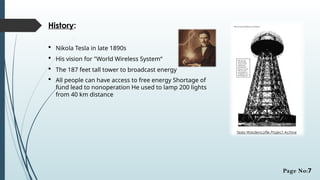
History:
Nikola Teslain late 1890s
His vision for "World Wireless System“
The 187 feet tall tower to broadcast energy
All people can have access to free energy Shortage of
fund lead to nonoperation He used to lamp 200 lights
from 40 km distance
Tesla Wardencyffe Project Achive
Page No:7
7.
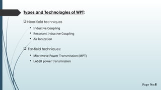
Types and Technologiesof WPT:
Near-field techniques
Inductive Coupling
Resonant Inductive Coupling
Air lonization
Far-field techniques:
Microwave Power Transmission (MPT)
LASER power transmission
Page No:8
8.
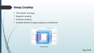
Energy Coupling:
Thetransfer of energy
Magnetic coupling
Inductive coupling
Simplest Wireless Energy coupling is a transformer
Transformer
Page No:9
9.
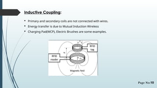
Inductive Coupling:
Primaryand secondary coils are not connected with wires.
Energy transfer is due to Mutual Induction Wireless
Charging Pad(WCP), Electric Brushes are some examples.
Page No:10
10.
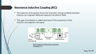
Resonance Inductive Coupling(RIC):
The capacitor and inductor forms the resonator. Charge oscillates between
inductor (as magnetic field) and capacitor (as electric field)
This type of oscillation is called resonance if the reactance's of the
inductor and capacitor are equal
Block Diagram Of Resonance Inductive
Coupling (RLC)
Page No:11
11.
How Resonance InRIC:
Coil provides the inductance
Capacitor is connected parallel to the coil
Radiation loss will be negligeibe
Energy will be shifting back and forth between magnetic field
surrounding the coil and electric field around the capacitor
Page No:12
12.
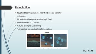
Air Ionization:
Toughesttechnique under near-field energy transfer
techniques
Air ionizes only when there is a high field
Needed field is 2.11MV/m
Natural example: Lightening
Not feasible for practical implementation
Page No:13
13.
Microwave Power Transfer(MPT):
Transfers high power from one place to another. Two places being in
line of sight usually
Electrical energy to microwave energy
Capturing microwaves using rectenna
Microwave energy to electrical energy
AC is converted to DC first
DC is converted to microwaves using magnetron
Transmitted waves are received at rectenna which rectifies,
gives
DC as the outputDC is converted back to AC
Page No:14
14.
LASER Transmission:
LASERis highly directional, coherent
Not dispersed for very long
But, gets attenuated when it propagates through
atmosphere
Simple receiver
Photovoltaic cell
Cost-efficient
Page No:15
15.
Solar Power Satellites(SPS):
To provide energy to earth's increasing energy need
To efficiently make use of renewable energy i.e., solar energy
SPS are placed in geostationary orbits
Each SPS may have 400 million photocells
Efficiency exceeds 95%, if microwave is used
Page No:16
16.
Advantages:
No wires
No Energy-waste as compared to dumped used batteries
Need for battery is eliminated
Maintenance cost is less
Page No:17
17.
Disadvantages:
Initial costis high
In RIC, tuning is difficult(L & C Values for Resonance)
Air ionization technique is not feasible(small distance, High voltage,)
Distance constraint
Page No:18
18.
The Qi Standard:
Qi(Chee) is a interface standard Developed by Wireless Power
Consortium
It works for a distance up to 40mm(1.6inches)
Comprises a transmission
Pad & a compatible receive
Page No:19
19.
Applications:
Near-field energytransfer
Electric automobile charging
Static and moving
Consumer electronics
Industrial purposes
Harsh environment
Far-field energy transfer
Solar Power Satellites
Energy to remote areas
Can broadcast energy globally (in future)
Page No:20
20.
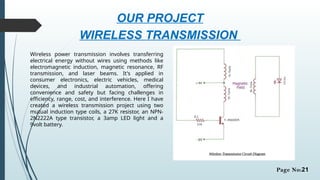
OUR PROJECT
WIRELESS TRANSMISSION
Wirelesspower transmission involves transferring
electrical energy without wires using methods like
electromagnetic induction, magnetic resonance, RF
transmission, and laser beams. It's applied in
consumer electronics, electric vehicles, medical
devices, and industrial automation, offering
convenience and safety but facing challenges in
efficiency, range, cost, and interference. Here I have
created a wireless transmission project using two
mutual induction type coils, a 27K resistor, an NPN-
2N2222A type transistor, a 3amp LED light and a
9volt battery.
Page No:21
21.
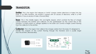
TRANSISTOR:
Emitter: This isthe region that releases or "emits" charge carriers (electrons or holes) into the
base. In an NPN transistor, the emitter is doped with an excess of electrons, while in a PNP
transistor, it has an excess of holes. (Forward Bias)
Base: This is the middle region, thin and lightly doped, which controls the flow of charge
carriers between the emitter and collector. It's the "gatekeeper" for the current flow in the
transistor. A small current or voltage applied to the base can control a larger current flowing
from the collector to the emitter.
Collector: This is the region that collects the charge carriers from the base. It's designed to
handle the majority of the current flowing through the transistor and is usually larger
than the emitter. (Reverse Bias)
Page
No:22
22.
WORKING PRINCIPLE OFWIRELESS TRANSMISSION:
Wireless transmission works by converting electrical energy into electromagnetic
waves, which then travel through the air to a receiver that converts the waves
back into usable electricity, essentially transferring power without the need for
physical wires; this principle is primarily based on electromagnetic induction,
where a changing magnetic field induces a current in a nearby conductor, like a
coil of wire, allowing for energy transfer between two coils positioned close
together.
Electromagnetic fields:
The core principle involves creating a time-varying electromagnetic field using a
transmitter coil that generates a magnetic field when current flows through it.
Receiver coil:
A nearby receiver coil, properly aligned with the transmitter coil, picks up the
magnetic field and induces a current within it, allowing for power transfer.
Page No:23
23.
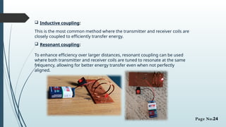
Inductive coupling:
Thisis the most common method where the transmitter and receiver coils are
closely coupled to efficiently transfer energy.
Resonant coupling:
To enhance efficiency over larger distances, resonant coupling can be used
where both transmitter and receiver coils are tuned to resonate at the same
frequency, allowing for better energy transfer even when not perfectly
aligned.
Page No:24
24.
Conclusion:
Transmission withoutwires- a reality
Efficient Low maintenance cost
But, high initial cost Better than conventional wired transfer
Energy crisis can be decreased Low loss
In near future, world will be completely wireless
Page No:25