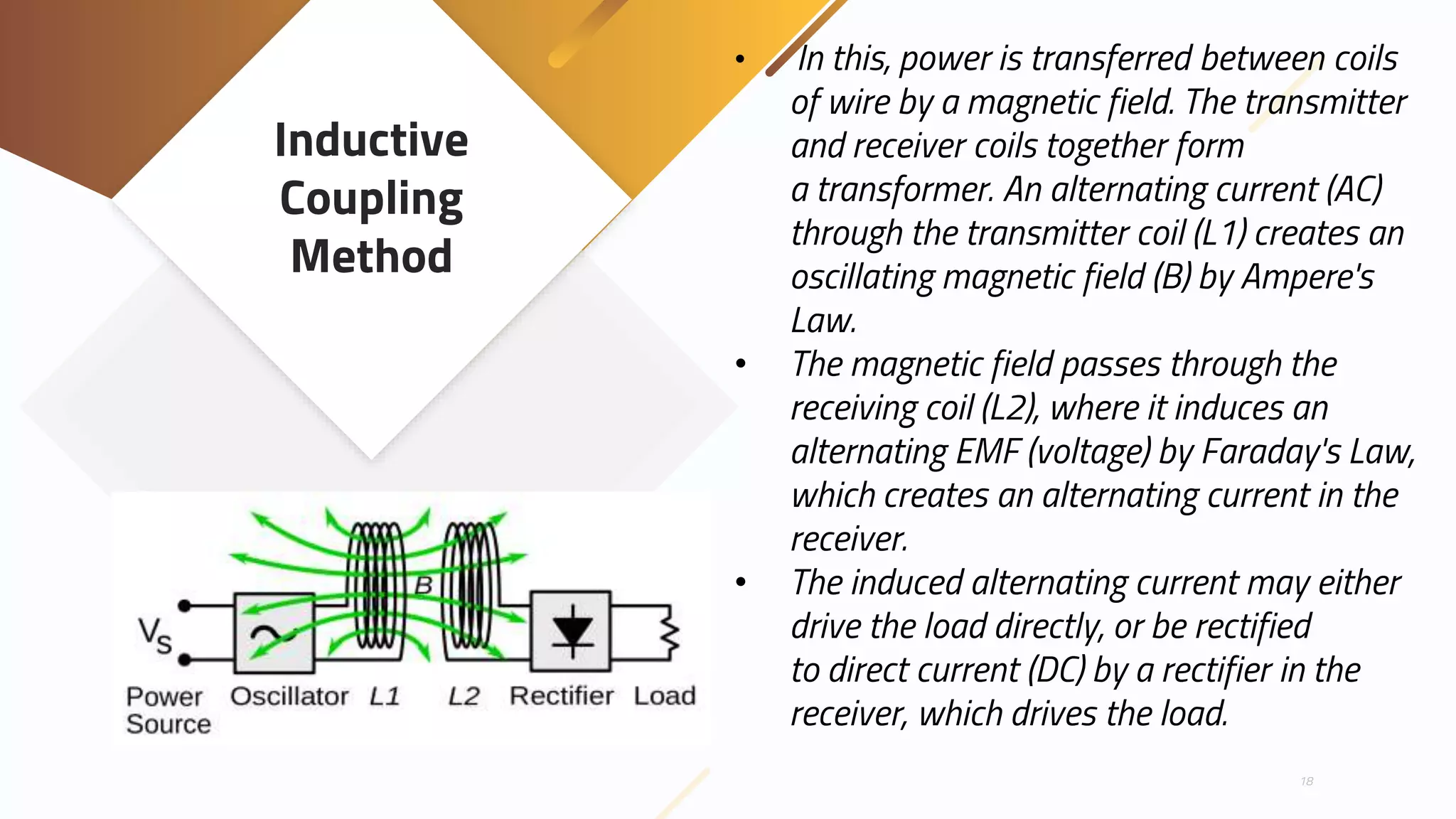
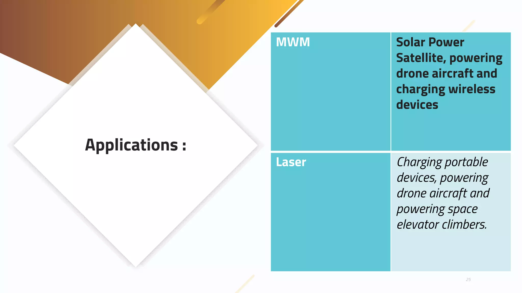
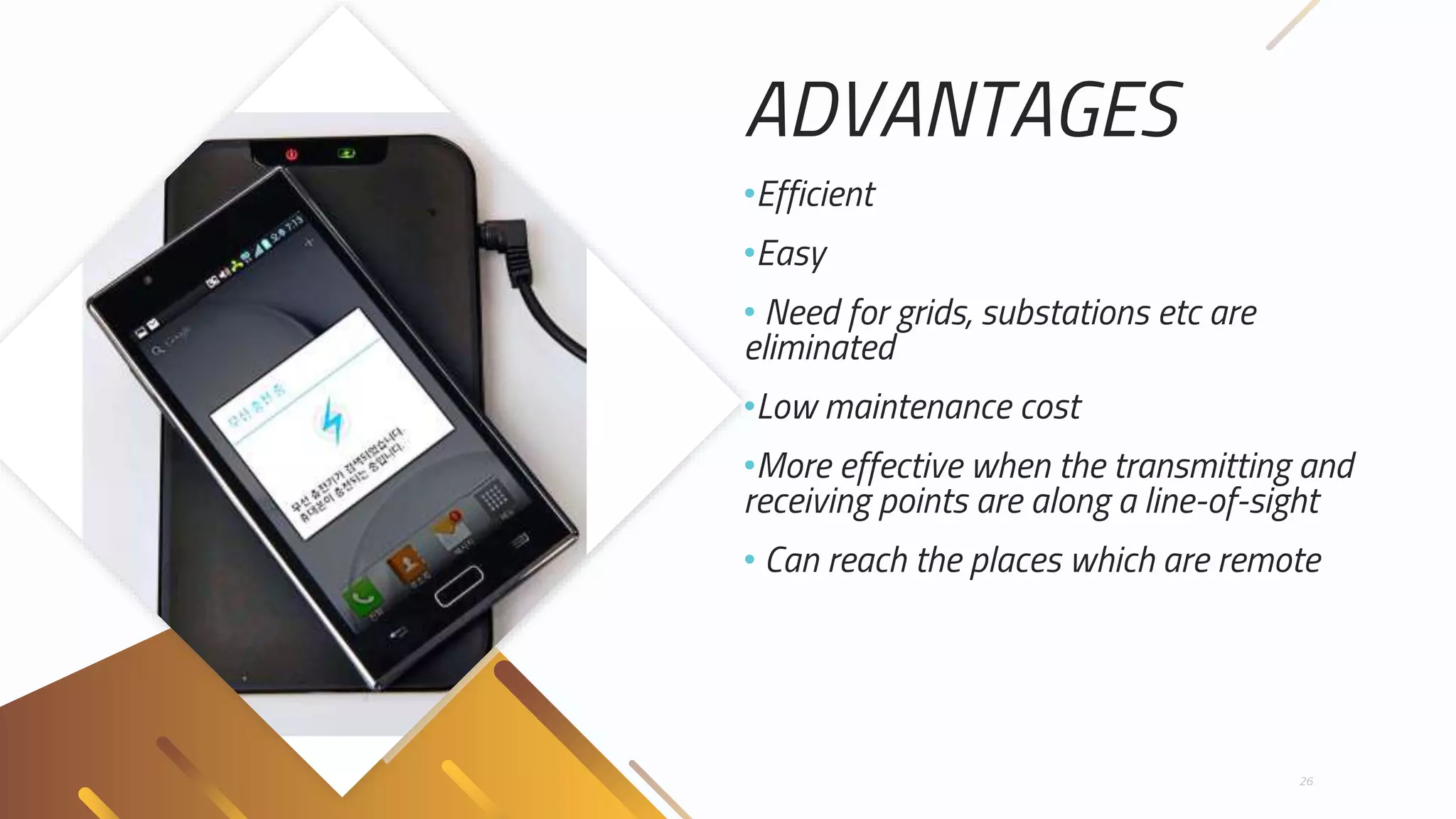
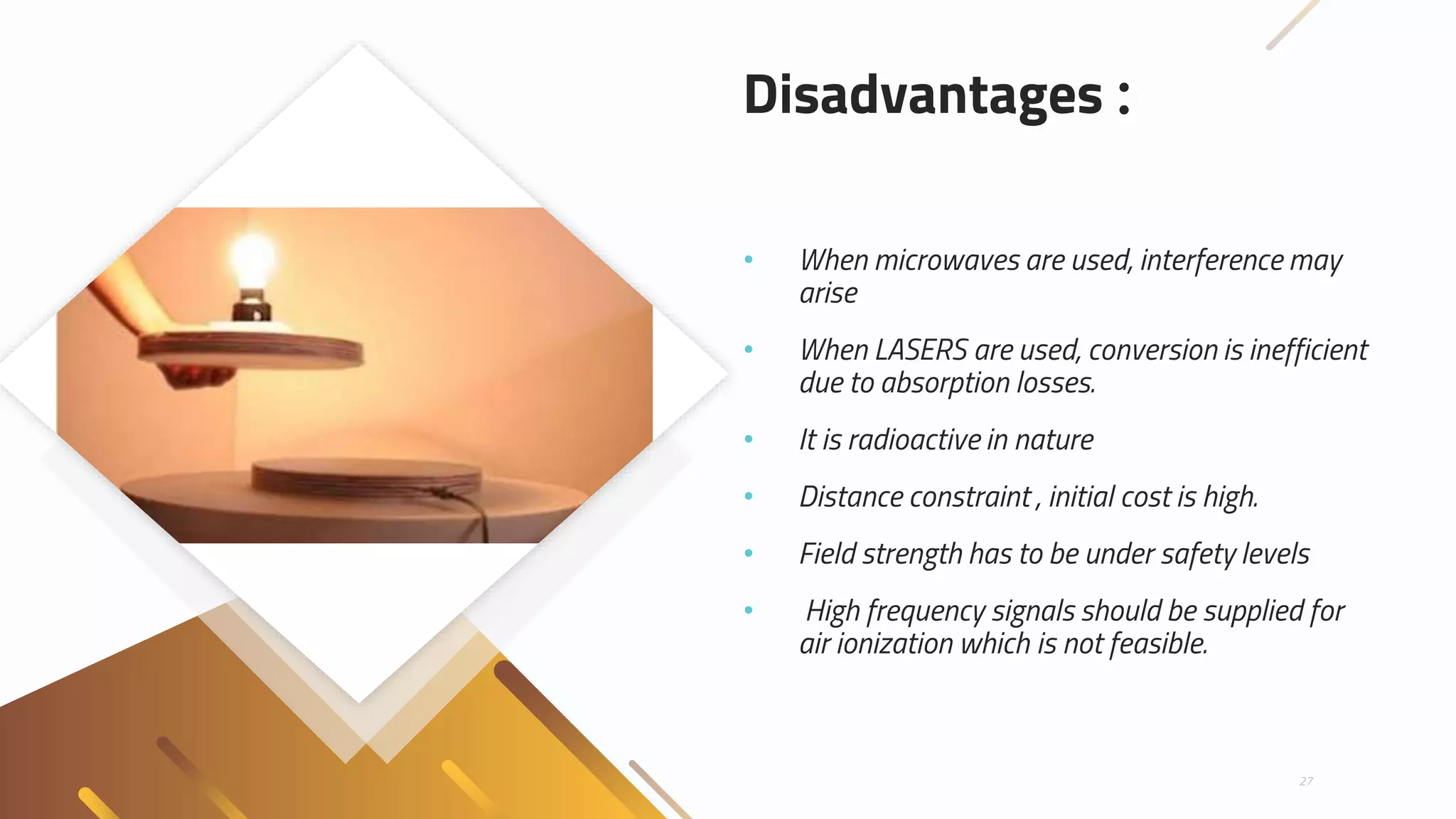
Wireless Power
Transmission
Submitted by : Himanshu Sirohi
Roll No : 1502910058
Branch : CSE
Semester : 8
1
Contents :
• DEFINITION
• REQUIREMENT
• HISTORY
• METHODS
• ADVANTAGES
• DISADVANTAGES
• CONCLUSION
• LATEST REASEARCH
2
Definition
• Wireless Power
Transfer (WPT), Wireless Power
Transmission, Wireless Energy
Transmission (WET),
or Electromagnetic Power Transfer
is the transmission of electrical
energy without wires as a physical
link.
3
Why we
need it ?
• One of the major issues in power
system is the losses occurring
during the transmission and
distribution of electrical power.
• The percentage of loss of power
during transmission and
distribution is approximated as
26% around the world.
• The main reason for power loss
during transmission and
distribution is the resistance of
wires used in grid.
4
• According to the World Resources
Institute (WRI), India’s electricity grid
has the highest transmission and
distribution losses in the world – a
whopping 40%.
• According to a report, published by the
Northeast Group, the Indian
power sector loses around $16.2 billion
to theft every year.
• According to the World Bank
estimates, Power
theft reduces India's GDP by around
1.5%.
• Wireless transmission is useful in cases
where interconnecting wires are
inconvenient, hazardous or
impossible to manage.
5
Since
When ?
• Sir NICOLA TESLA was the first one to propose
and research the idea of wireless transmission in
1890, since than many scholars and scientists
have been working to make his dream a reality.
• Experiment in resonant inductive transfer by
Tesla at Colorado Springs 1899. The coil is in
resonance with Tesla's magnifying transmitter
nearby, powering the light bulb at bottom.
6
In 1901, at Shoreham, New York he attempted
to construct a large high-voltage wireless power
station, now called Wardenclyffe Tower , but by
1904 investment dried up and the facility was
never completed.
7
Tesla's unsuccessful Wardenclyffe
power station.
How it will
be done ?
⇢ In a wireless power transmission system, a
transmitter device, driven by electric power
from a power source, generates a time-
varying electromagnetic field, which
transmits power across space to a receiver
device, which extracts power from the field
and supplies it to an electric load.
8
Methods
Different methods of transmission proposed
by different scientist and scholars are:
1. Atmospheric conduction method of
Tesla
2. Electrodynamic induction method:
• Microwave method
• Laser method
9
Atmospheric
Conduction
Method
• In 1899, Sir NICOLA TESLA and HEINRICH HERTZ
powered a fluorescent lamp keeping it 25 miles
away from source without using wire. Wireless
power transmission experiments at WARDEN
CLYFFE High frequency current, of a Tesla coil,
could light lamps filled with gas (like neon). In
this method a closed circuit is made using
transmitter, ionized path between upper
atmosphere and transmitter, second ionized
path connecting receiver. The circuit back to the
transmitter is completed through the earth.
• High potential is maintained at transmitter and
receiver end. A high potential transmitter
transmits an “electric impulse” through the
ionized path to the upper atmosphere where it
ionizes the air, and this air between the
transmitter and receiver would conduct like a
neon tube .
10
Limitations
of ACM
• Economically challenging.
• Periodic changes in atmospheric
condition.
• Maintaining high tower potential
every time.
11
Electro
Magnetic
Induction
Method
12
This method uses electromagnetic
radiation, which uses far field technique
in order to achieve range into
kilometers, and includes two techniques:
• LASERS
•MICROWAVE
Laser
Transmission
• In the case of electromagnetic
radiation closer to visible region of
spectrum (10s of microns (um) to 10s
of nm),power can be transmitted by
converting electricity into a laser
beam that is then pointed at a solar
cell receiver.
• This mechanism is generally known as
"power beaming" because the power
is beamed at a receiver that can
convert it to usable electrical energy.
• At the receiver, special photovoltaic
laser power converters which are
optimized for monochromatic light
conversion are applied.
13
Real Life
Application
of Laser
14
A laser beam centered on a
panel of photovoltaic cells
provides enough power to a
lightweight model airplane
for it to fly.
Disadvantages of
Laser
⇢ Laser radiation is hazardous. Without
a proper safety mechanism, low
power levels can blind humans and
other animals. High power levels can
kill through localized spot heating.
⇢ Conversion between electricity and
light is limited. Photovoltaic cells
achieve 40%–50% efficiency.
⇢ Requires a direct line of sight with the
target.
15
Micro Wave
Method
• Power transmission via radio waves can
be made more directional, allowing longer
distance power beaming, with shorter
wavelengths of electromagnetic radiation,
typically in the microwave range.
• A rectenna may be used to convert the
microwave energy back into electricity.
Rectenna conversion efficiencies
exceeding 95% have been realized. Power
beaming using microwaves has been
proposed for the transmission of energy
from orbiting solar power satellites to
Earth.
• The principle of Evanescent principle of
Electromagnetic Wave Coupling extends
the induction.
16
Real Life
Application
of MWM
17
The depiction of a solar
satellite that could send
electric energy by
microwaves to a space
vessel or planetary surface.
Inductive
Coupling
Method
18
• In this, power is transferred between coils
of wire by a magnetic field. The transmitter
and receiver coils together form
a transformer. An alternating current (AC)
through the transmitter coil (L1) creates an
oscillating magnetic field (B) by Ampere's
Law.
• The magnetic field passes through the
receiving coil (L2), where it induces an
alternating EMF (voltage) by Faraday's Law,
which creates an alternating current in the
receiver.
• The induced alternating current may either
drive the load directly, or be rectified
to direct current (DC) by a rectifier in the
receiver, which drives the load.
Real Life
Application
of ICM
19
Modern inductive power transfer, an
electric toothbrush charger. A coil in the
stand produces a magnetic field, inducing
an alternating current in a coil in the
toothbrush, which is rectified to charge
the batteries.
Real Life
Application
Of ICM
Powermat inductive charging spots in a
coffee shop. Customers can set their
phones and computers on them to
recharge.
20
Real Life
Application
of ICM
21
Wireless powered access card.
Capacitive
Coupling
Method
• In this, energy is transmitted by electric fields
between electrodes such as metal plates. The
transmitter and receiver electrodes form
a capacitor, with the intervening space as the
dielectric.
• An alternating voltage generated by the
transmitter is applied to the transmitting plate,
and the oscillating electric field induces an
alternating potential on the receiver plate
by electrostatic induction, which causes an
alternating current to flow in the load circuit.
• The amount of power transferred increases
with the frequency, the square of the voltage,
and the capacitance between the plates, which
is proportional to the area of the smaller plate
and (for short distances) inversely proportional
to the separation
22
Generic
Block
Diagram
Of CCM
23
• In this, there are two transmitter plates and two
receiver plates. Each transmitter plate is coupled to a
receiver plate. The transmitter oscillator drives the
transmitter plates in opposite phase (180° phase
difference) by a high alternating voltage, and the load
is connected between the two receiver plates.
• The alternating electric fields induce opposite phase
alternating potentials in the receiver plates, and this
"push-pull" action causes current to flow back and
forth between the plates through the load.
Applications :
ICM Electric tooth
brush, razor
battery charging,
induction
stovetops and
industrial heaters.
CCM Charging portable
devices, power
routing in large-
scale integrated
circuits, Smart cards
and biomedical
implants
24
Applications :
MWM Solar Power
Satellite, powering
drone aircraft and
charging wireless
devices
Laser Charging portable
devices, powering
drone aircraft and
powering space
elevator climbers.
25
ADVANTAGES
•Efficient
•Easy
• Need for grids, substations etc are
eliminated
•Low maintenance cost
•More effective when the transmitting and
receiving points are along a line-of-sight
• Can reach the places which are remote
26
Disadvantages :
• When microwaves are used, interference may
arise
• When LASERS are used, conversion is inefficient
due to absorption losses.
• It is radioactive in nature
• Distance constraint , initial cost is high.
• Field strength has to be under safety levels
• High frequency signals should be supplied for
air ionization which is not feasible.
27
Conclusion :
• Transmission without wires- a reality
• Efficient
• Low maintenance cost. But, high initial
cost
• Better than conventional wired transfer
• Energy crisis can be decreased
• Low loss
• In near future, world will be completely
wireless
28
Latest
Research :
29
Thank You
30

Wireless power transmission new and improved

  • 1.
    Wireless Power Transmission Submitted by: Himanshu Sirohi Roll No : 1502910058 Branch : CSE Semester : 8 1
  • 2.
    Contents : • DEFINITION •REQUIREMENT • HISTORY • METHODS • ADVANTAGES • DISADVANTAGES • CONCLUSION • LATEST REASEARCH 2
  • 3.
    Definition • Wireless Power Transfer(WPT), Wireless Power Transmission, Wireless Energy Transmission (WET), or Electromagnetic Power Transfer is the transmission of electrical energy without wires as a physical link. 3
  • 4.
    Why we need it? • One of the major issues in power system is the losses occurring during the transmission and distribution of electrical power. • The percentage of loss of power during transmission and distribution is approximated as 26% around the world. • The main reason for power loss during transmission and distribution is the resistance of wires used in grid. 4
  • 5.
    • According tothe World Resources Institute (WRI), India’s electricity grid has the highest transmission and distribution losses in the world – a whopping 40%. • According to a report, published by the Northeast Group, the Indian power sector loses around $16.2 billion to theft every year. • According to the World Bank estimates, Power theft reduces India's GDP by around 1.5%. • Wireless transmission is useful in cases where interconnecting wires are inconvenient, hazardous or impossible to manage. 5
  • 6.
    Since When ? • SirNICOLA TESLA was the first one to propose and research the idea of wireless transmission in 1890, since than many scholars and scientists have been working to make his dream a reality. • Experiment in resonant inductive transfer by Tesla at Colorado Springs 1899. The coil is in resonance with Tesla's magnifying transmitter nearby, powering the light bulb at bottom. 6
  • 7.
    In 1901, atShoreham, New York he attempted to construct a large high-voltage wireless power station, now called Wardenclyffe Tower , but by 1904 investment dried up and the facility was never completed. 7 Tesla's unsuccessful Wardenclyffe power station.
  • 8.
    How it will bedone ? ⇢ In a wireless power transmission system, a transmitter device, driven by electric power from a power source, generates a time- varying electromagnetic field, which transmits power across space to a receiver device, which extracts power from the field and supplies it to an electric load. 8
  • 9.
    Methods Different methods oftransmission proposed by different scientist and scholars are: 1. Atmospheric conduction method of Tesla 2. Electrodynamic induction method: • Microwave method • Laser method 9
  • 10.
    Atmospheric Conduction Method • In 1899,Sir NICOLA TESLA and HEINRICH HERTZ powered a fluorescent lamp keeping it 25 miles away from source without using wire. Wireless power transmission experiments at WARDEN CLYFFE High frequency current, of a Tesla coil, could light lamps filled with gas (like neon). In this method a closed circuit is made using transmitter, ionized path between upper atmosphere and transmitter, second ionized path connecting receiver. The circuit back to the transmitter is completed through the earth. • High potential is maintained at transmitter and receiver end. A high potential transmitter transmits an “electric impulse” through the ionized path to the upper atmosphere where it ionizes the air, and this air between the transmitter and receiver would conduct like a neon tube . 10
  • 11.
    Limitations of ACM • Economicallychallenging. • Periodic changes in atmospheric condition. • Maintaining high tower potential every time. 11
  • 12.
    Electro Magnetic Induction Method 12 This method useselectromagnetic radiation, which uses far field technique in order to achieve range into kilometers, and includes two techniques: • LASERS •MICROWAVE
  • 13.
    Laser Transmission • In thecase of electromagnetic radiation closer to visible region of spectrum (10s of microns (um) to 10s of nm),power can be transmitted by converting electricity into a laser beam that is then pointed at a solar cell receiver. • This mechanism is generally known as "power beaming" because the power is beamed at a receiver that can convert it to usable electrical energy. • At the receiver, special photovoltaic laser power converters which are optimized for monochromatic light conversion are applied. 13
  • 14.
    Real Life Application of Laser 14 Alaser beam centered on a panel of photovoltaic cells provides enough power to a lightweight model airplane for it to fly.
  • 15.
    Disadvantages of Laser ⇢ Laserradiation is hazardous. Without a proper safety mechanism, low power levels can blind humans and other animals. High power levels can kill through localized spot heating. ⇢ Conversion between electricity and light is limited. Photovoltaic cells achieve 40%–50% efficiency. ⇢ Requires a direct line of sight with the target. 15
  • 16.
    Micro Wave Method • Powertransmission via radio waves can be made more directional, allowing longer distance power beaming, with shorter wavelengths of electromagnetic radiation, typically in the microwave range. • A rectenna may be used to convert the microwave energy back into electricity. Rectenna conversion efficiencies exceeding 95% have been realized. Power beaming using microwaves has been proposed for the transmission of energy from orbiting solar power satellites to Earth. • The principle of Evanescent principle of Electromagnetic Wave Coupling extends the induction. 16
  • 17.
    Real Life Application of MWM 17 Thedepiction of a solar satellite that could send electric energy by microwaves to a space vessel or planetary surface.
  • 18.
    Inductive Coupling Method 18 • In this,power is transferred between coils of wire by a magnetic field. The transmitter and receiver coils together form a transformer. An alternating current (AC) through the transmitter coil (L1) creates an oscillating magnetic field (B) by Ampere's Law. • The magnetic field passes through the receiving coil (L2), where it induces an alternating EMF (voltage) by Faraday's Law, which creates an alternating current in the receiver. • The induced alternating current may either drive the load directly, or be rectified to direct current (DC) by a rectifier in the receiver, which drives the load.
  • 19.
    Real Life Application of ICM 19 Moderninductive power transfer, an electric toothbrush charger. A coil in the stand produces a magnetic field, inducing an alternating current in a coil in the toothbrush, which is rectified to charge the batteries.
  • 20.
    Real Life Application Of ICM Powermatinductive charging spots in a coffee shop. Customers can set their phones and computers on them to recharge. 20
  • 21.
  • 22.
    Capacitive Coupling Method • In this,energy is transmitted by electric fields between electrodes such as metal plates. The transmitter and receiver electrodes form a capacitor, with the intervening space as the dielectric. • An alternating voltage generated by the transmitter is applied to the transmitting plate, and the oscillating electric field induces an alternating potential on the receiver plate by electrostatic induction, which causes an alternating current to flow in the load circuit. • The amount of power transferred increases with the frequency, the square of the voltage, and the capacitance between the plates, which is proportional to the area of the smaller plate and (for short distances) inversely proportional to the separation 22
  • 23.
    Generic Block Diagram Of CCM 23 • Inthis, there are two transmitter plates and two receiver plates. Each transmitter plate is coupled to a receiver plate. The transmitter oscillator drives the transmitter plates in opposite phase (180° phase difference) by a high alternating voltage, and the load is connected between the two receiver plates. • The alternating electric fields induce opposite phase alternating potentials in the receiver plates, and this "push-pull" action causes current to flow back and forth between the plates through the load.
  • 24.
    Applications : ICM Electrictooth brush, razor battery charging, induction stovetops and industrial heaters. CCM Charging portable devices, power routing in large- scale integrated circuits, Smart cards and biomedical implants 24
  • 25.
    Applications : MWM SolarPower Satellite, powering drone aircraft and charging wireless devices Laser Charging portable devices, powering drone aircraft and powering space elevator climbers. 25
  • 26.
    ADVANTAGES •Efficient •Easy • Need forgrids, substations etc are eliminated •Low maintenance cost •More effective when the transmitting and receiving points are along a line-of-sight • Can reach the places which are remote 26
  • 27.
    Disadvantages : • Whenmicrowaves are used, interference may arise • When LASERS are used, conversion is inefficient due to absorption losses. • It is radioactive in nature • Distance constraint , initial cost is high. • Field strength has to be under safety levels • High frequency signals should be supplied for air ionization which is not feasible. 27
  • 28.
    Conclusion : • Transmissionwithout wires- a reality • Efficient • Low maintenance cost. But, high initial cost • Better than conventional wired transfer • Energy crisis can be decreased • Low loss • In near future, world will be completely wireless 28
  • 29.
  • 30.